


M4A78-HTPC |
Motherboard |
Series |
|
|
|

E4642
Second Edition V2
April 2009
Copyright © 2009 ASUSTeK Computer Inc. All Rights Reserved.
No part of this manual, including the products and software described in it, may be reproduced, transmitted, transcribed, stored in a retrieval system, or translated into any language in any form or by any means, except documentation kept by the purchaser for backup purposes, without the express written permission of ASUSTeK Computer Inc. (“ASUS”).
Product warranty or service will not be extended if: (1) the product is repaired, modified or altered, unless such repair, modification of alteration is authorized in writing byASUS; or (2) the serial number of the product is defaced or missing.
ASUS PROVIDES THIS MANUAL “AS IS” WITHOUT WARRANTY OF ANY KIND, EITHER EXPRESS OR IMPLIED, INCLUDING BUT NOT LIMITED TO THE IMPLIED WARRANTIES OR CONDITIONS OF MERCHANTABILITY OR FITNESS FOR A PARTICULAR PURPOSE. IN NO EVENT SHALL ASUS, ITS DIRECTORS, OFFICERS, EMPLOYEES OR AGENTS BE LIABLE FOR ANY INDIRECT, SPECIAL, INCIDENTAL, OR CONSEQUENTIAL DAMAGES (INCLUDING DAMAGES FOR LOSS OF PROFITS, LOSS OF BUSINESS, LOSS OF USE OR DATA, INTERRUPTION OF BUSINESS AND THE LIKE), EVEN IF ASUS HAS BEEN ADVISED OF THE POSSIBILITY OF SUCH DAMAGES ARISING FROM ANY DEFECT OR ERROR IN THIS MANUAL OR PRODUCT.
SPECIFICATIONS AND INFORMATION CONTAINED IN THIS MANUAL ARE FURNISHED FOR INFORMATIONAL USE ONLY, AND ARE SUBJECT TO CHANGE AT ANY TIME WITHOUT NOTICE, AND SHOULD NOT BE CONSTRUED AS A COMMITMENT BY ASUS. ASUS ASSUMES NO RESPONSIBILITY OR LIABILITY FOR ANY ERRORS OR INACCURACIES THAT MAY APPEAR IN THIS MANUAL, INCLUDING THE PRODUCTS AND SOFTWARE DESCRIBED IN IT.
Products and corporate names appearing in this manual may or may not be registered trademarks or copyrights of their respective companies, and are used only for identification or explanation and to the owners’ benefit, without intent to infringe.
ii

Contents
Contents....................................................................................................... |
iii |
Notices......................................................................................................... |
vi |
Safety information...................................................................................... |
vii |
About this guide......................................................................................... |
vii |
M4A78-HTPC specifications summary...................................................... |
ix |
Chapter 1 |
Product introduction |
|
|
1.1 |
Welcome!....................................................................................... |
1-1 |
|
1.2 |
Package contents......................................................................... |
1-1 |
|
1.3 |
Special features............................................................................ |
1-1 |
|
|
1.3.1 |
Product highlights ............................................................ |
1-1 |
|
1.3.2 |
Innovative ASUS features ................................................ |
1-2 |
1.4 |
Before you proceed...................................................................... |
1-4 |
|
1.5 |
Motherboard overview................................................................. |
1-5 |
|
|
1.5.1 |
Placement direction ......................................................... |
1-5 |
|
1.5.2 |
Screw holes ..................................................................... |
1-5 |
|
1.5.3 |
Motherboard layout .......................................................... |
1-6 |
|
1.5.4 |
Layout contents . .............................................................. |
1-6 |
1.6 |
Central Processing Unit (CPU).................................................... |
1-7 |
|
|
1.6.1 |
Installing the CPU ............................................................ |
1-7 |
|
1.6.2 |
Installing the heatsink and fan ......................................... |
1-8 |
1.7 |
System memory.......................................................................... |
1-10 |
|
|
1.7.1 |
Overview ........................................................................ |
1-10 |
|
1.7.2 |
Memory configurations . ................................................. |
1-10 |
|
1.7.3 |
Installing a DIMM ........................................................... |
1-15 |
|
1.7.4 |
Removing a DIMM ......................................................... |
1-15 |
1.8 |
Expansion slots.......................................................................... |
1-16 |
|
|
1.8.1 |
Installing an expansion card .......................................... |
1-16 |
|
1.8.2 |
Configuring an expansion card ...................................... |
1-16 |
|
1.8.3 |
PCI slot .......................................................................... |
1-16 |
|
1.8.4 |
PCI Express x1 slots ..................................................... |
1-16 |
|
1.8.5 |
PCI Express 2.0 x16 slot . .............................................. |
1-16 |
1.9 |
Jumpers |
....................................................................................... |
1-17 |
1.10 |
Connectors.................................................................................. |
1-18 |
|
|
1.10.1 .................................................. |
Rear panel connectors |
1-18 |
|
1.10.2 ........................................................ |
Internal connectors |
1-22 |
iii

Contents
1.11 Software support........................................................................ |
1-31 |
|
1.11.1 Installing an operating system....................................... |
1-31 |
|
1.11.2 |
Support DVD information............................................... |
1-31 |
1.11.3 |
ASUS Home Theater Gate............................................ |
1-32 |
Chapter 2 |
BIOS information |
|
|
2.1 |
Managing and updating your BIOS............................................. |
2-1 |
|
|
2.1.1 |
ASUS Update utility......................................................... |
2-1 |
|
2.1.2 |
ASUS EZ Flash 2 utility................................................... |
2-2 |
|
2.1.3 |
ASUS CrashFree BIOS 3 utility....................................... |
2-3 |
2.2 |
BIOS setup program..................................................................... |
2-3 |
|
|
2.2.1 |
BIOS menu screen.......................................................... |
2-4 |
|
2.2.2 |
Menu bar......................................................................... |
2-4 |
|
2.2.3 |
Navigation keys............................................................... |
2-5 |
|
2.2.4 |
Menu items...................................................................... |
2-5 |
|
2.2.5 |
Submenu items................................................................ |
2-5 |
|
2.2.6 |
Configuration fields.......................................................... |
2-5 |
|
2.2.7 |
General help.................................................................... |
2-5 |
|
2.2.8 |
Pop-up window................................................................ |
2-5 |
|
2.2.9 |
Scroll bar......................................................................... |
2-5 |
2.3 |
Main menu..................................................................................... |
2-6 |
|
|
2.3.1 |
System Time [xx:xx:xx].................................................... |
2-6 |
|
2.3.2 |
System Date [Day xx/xx/xxxx]......................................... |
2-6 |
|
2.3.3 |
Language [English].......................................................... |
2-6 |
|
2.3.4 |
SATA1/SATA3................................................................ |
2-6 |
|
2.3.5 |
SATA1–5/ESATA............................................................ |
2-7 |
|
2.3.6 |
SATAConfiguration.......................................................... |
2-8 |
|
2.3.7 |
System Information.......................................................... |
2-8 |
2.4 |
Advanced menu............................................................................ |
2-9 |
|
|
2.4.1 |
JumperFree Configuration............................................... |
2-9 |
|
2.4.2 |
CPU Configuration......................................................... |
2-12 |
|
2.4.3 |
Chipset.......................................................................... |
2-13 |
|
2.4.4 |
Onboard Devices Configuration.................................... |
2-15 |
|
2.4.5 |
PCIPnP.......................................................................... |
2-15 |
|
2.4.6 |
USB Configuration......................................................... |
2-15 |
iv

Contents
2.5 |
Power menu................................................................................ |
2-16 |
|
|
2.5.1 |
Suspend Mode [Auto].................................................... |
2-16 |
|
2.5.2 |
ACPI 2.0 Support [Disabled].......................................... |
2-17 |
|
2.5.3 |
ACPIAPIC Support [Enabled]....................................... |
2-17 |
|
2.5.4 |
APM Configuration........................................................ |
2-17 |
|
2.5.5 |
Hardware Monitor.......................................................... |
2-17 |
2.6 |
Boot menu................................................................................... |
2-18 |
|
|
2.6.1 |
Boot Device Priority....................................................... |
2-19 |
|
2.6.2 |
Boot Settings Configuration........................................... |
2-19 |
|
2.6.3 |
Security.......................................................................... |
2-19 |
2.7 |
Tools menu.................................................................................. |
2-21 |
|
|
2.7.1 |
ASUS EZ Flash 2.......................................................... |
2-21 |
|
2.7.2 |
Express Gate [Auto]...................................................... |
2-21 |
|
2.7.3 |
AI NET 2........................................................................ |
2-21 |
2.8 |
Exit menu..................................................................................... |
2-22 |
|

Notices
Federal Communications Commission Statement
This device complies with Part 15 of the FCC Rules. Operation is subject to the following two conditions:
•This device may not cause harmful interference, and
•This device must accept any interference received including interference that may cause undesired operation.
This equipment has been tested and found to comply with the limits for a Class B digital device, pursuant to Part 15 of the FCC Rules. These limits are designed to provide reasonable protection against harmful interference in a residential installation. This equipment generates, uses and can radiate radio frequency energy and, if not installed and used in accordance with manufacturer’s instructions, may cause harmful interference to radio communications. However, there is no guarantee that interference will not occur in a particular installation. If this equipment does cause harmful interference to radio or
television reception, which can be determined by turning the equipment off and on, the user is encouraged to try to correct the interference by one or more of the following measures:
•Reorient or relocate the receiving antenna.
•Increase the separation between the equipment and receiver.
•Connect the equipment to an outlet on a circuit different from that to which the receiver is connected.
•Consult the dealer or an experienced radio/TV technician for help.
The use of shielded cables for connection of the monitor to the graphics card is required to assure compliance with FCC regulations. Changes or modifications to this unit not expressly approved by the party responsible for compliance could void the user’s authority to operate this equipment.
Canadian Department of Communications Statement
This digital apparatus does not exceed the Class B limits for radio noise emissions from digital apparatus set out in the Radio Interference Regulations of the Canadian Department of Communications.
This class B digital apparatus complies with Canadian ICES-003.
REACH
Complying with the REACH (Registration, Evaluation, Authorisation, and Restriction of Chemicals) regulatory framework, we published the chemical substances in our products at
ASUS REACH website at http://green.asus.com/english/REACH.htm.
DO NOT throw the motherboard in municipal waste. This product has been designed to enable proper reuse of parts and recycling. This symbol of the crossed out wheeled bin indicates that the product (electrical and electronic equipment) should not be placed in municipal waste. Check local regulations for disposal of electronic products.
DO NOT throw the mercury-containing button cell battery in municipal waste. This symbol of the crossed out wheeled bin indicates that the battery should not be placed in municipal waste.
vi

Safety information
Electrical safety
•To prevent electrical shock hazard, disconnect the power cable from the electrical outlet before relocating the system.
•When adding or removing devices to or from the system, ensure that the power cables for the devices are unplugged before the signal cables are connected. If possible, disconnect all power cables from the existing system before you add a device.
•Before connecting or removing signal cables from the motherboard, ensure that all power cables are unplugged.
•Seek professional assistance before using an adapter or extension cord. These devices could interrupt the grounding circuit.
•Ensure that your power supply is set to the correct voltage in your area. If you are not sure about the voltage of the electrical outlet you are using, contact your local power company.
•If the power supply is broken, do not try to fix it by yourself. Contact a qualified service technician or your retailer.
Operation safety
•Before installing the motherboard and adding devices on it, carefully read all the manuals that came with the package.
•Before using the product, ensure that all cables are correctly connected and the power cables are not damaged. If you detect any damage, contact your dealer immediately.
•To avoid short circuits, keep paper clips, screws, and staples away from connectors, slots, sockets and circuitry.
•Avoid dust, humidity, and temperature extremes. Do not place the product in any area where it may become wet.
•Place the product on a stable surface.
•If you encounter technical problems with the product, contact a qualified service technician or your retailer.
About this guide
This user guide contains the information you need when installing and configuring the motherboard.
How this guide is organized
This guide contains the following parts:
•Chapter 1: Product introduction
This chapter describes the features of the motherboard and the new technology it supports.
•Chapter 2: BIOS setup
This chapter tells how to change system settings through the BIOS Setup menus. Detailed descriptions of the BIOS parameters are also provided.
vii

Conventions used in this guide
To ensure that you perform certain tasks properly, take note of the following symbols used throughout this manual.
DANGER/WARNING: Information to prevent injury to yourself when trying to complete a task.
CAUTION: Information to prevent damage to the components when trying to complete a task.
IMPORTANT: Instructions that you MUST follow to complete a task.
NOTE: Tips and additional information to help you complete a task.
Where to find more information
Refer to the following sources for additional information and for product and software updates.
1.ASUS websites
The ASUS website provides updated information on ASUS hardware and software products. Refer to the ASUS contact information.
2.Optional documentation
Your product package may include optional documentation, such as warranty flyers, that may have been added by your dealer. These documents are not part of the standard package.
Typography
Bold text |
Indicates a menu or an item to select. |
Italics |
Used to emphasize a word or a phrase. |
<Key> |
Keys enclosed in the less-than and greater-than sign means |
|
that you must press the enclosed key. |
|
Example: <Enter> means that you must press the Enter or |
|
Return key. |
<Key1>+<Key2>+<Key3> |
If you must press two or more keys simultaneously, the key |
|
names are linked with a plus sign (+). |
|
Example: <Ctrl>+<Alt>+<D> |
Command |
Means that you must type the command exactly as shown, |
|
then supply the required item or value enclosed in brackets. |
|
Example: At the DOS prompt, type the command line: |
|
afudos /iM4A78HT.ROM |
viii

M4A78-HTPC specifications summary
CPU |
AMD® Phenom™ X4 / Phenom™ X3 /Athlon™ X2 / |
|
Athlon™ / Sempron™ processors (socketAM2+/AM2) |
|
SupportsAM3 Phenom™ II /Athlon™ X4/Athlon™ X3 / |
|
Athlon™ X2 |
|
AMD® 45nm CPU support |
|
AMD Cool’n’Quiet™ Technology |
Chipset |
AMD® 780G / SB700 |
System bus |
Up to 5200 MT/s; HyperTransport™ 3.0 interface for |
|
AM3 /AM2+ CPU |
|
2000 / 1600 MT/s forAM2 CPU |
Memory |
Dual-channel memory architecture |
|
- 4 x 240-pin DIMM sockets support unbufferred |
|
ECC / non-ECC DDR2 1066* / 800 / 667 MHz |
|
memory modules |
|
- Supports up to 16GB system memory |
|
* Due toAMD® CPU limitation, DDR2 1066 is supported by |
|
AM3 /AM2+ CPUs for one DIMM per channel only. Refer |
|
to www.asus.com or this user manual for the Memory QVL |
|
(Qualified Vendors Lists). |
|
** Due to OS limitation, when installing total memory of 4GB |
|
capacity or more, Windows 32-bit operation system may |
|
only recognize less than 3GB. Hence, a total installed |
|
memory of less than 3GB is recommended. |
VGA |
IntegratedATI Radeon™ HD 3200 GPU |
|
- Supports HDMI™ Technology with max. resolution up |
|
to 1920 x 1200 (1080P) |
|
- Supports Dual-link DVI with max. resolution up to |
|
2560 x 1600 @ 60Hz |
|
- Supports D-Sub with max. resolution up to |
|
2560 x 1440 @ 75Hz for 16:9 format |
|
- Hybrid CrossFireX™ support |
|
HDMI / DVI / D-Sub support (Dual independent |
|
displays support with HDMI / DVI and D-Sub) |
|
- Supports Microsoft® DirectX 10, OpenGL 2.0, Pixel |
|
Shader 4.0 |
|
- Hardware DecodeAcceleration for H.264, VC-1, and |
|
MPEG-2 |
|
- Maximum shared memory of 256MB |
Expansion Slots |
1 x PCIe 2.0 x16 slot |
|
2 x PCIe x1 slots |
|
1 x PCI 2.2 slot |
|
(continued on the next page) |
ix

M4A78-HTPC specifications summary
Storage
LAN
High Definition Audio
USB
AI Lifestyle Unique
Features
Other Features
1 x Ultra DMA133/100/66 for up to 2 PATAdevices
5 x SATA3.0 Gb/s ports with RAID 0, 1 and 10 support 1 x External SATA3.0 Gb/s port
* Due to Window® XP/Vista™ limitation, the RAID array with the total capacity over 2TB cannot be set as a boot disk.A RAID array over 2TB can only be set as a data disk only.
Atheros® L1E Gigabit LAN controller featuringAI NET 2
10-channel High DefinitionAudio CODEC
- Supports Jack-Detection and Multi-Streaming
- Optical/Coaxial S/PDIF Out ports at back I/O - 2-channel gold-plated RCAoutput at back I/O
- DTS Surround Sensation UltraPC
- ASUS Noise Filter
10 x USB 2.0 /1.1 ports (6 ports at midboard; 4 ports at back panel)
ASUS Power Solution:
- ASUS 4+1 Phase Power Design
ASUS Absolute Pitch Hi-Fi
ASUS Quiet Thermal Solution:
- ASUS Tranquil Mode (AM3/AM2+ CPUs only)
- ASUS Fanless Design: heatsink solution
ASUS Express Gate
ASUS Home Theater Gate
ASUS Crystal Sound
- ASUS Noise Filter
ASUS EZ DIY
- ASUS Q-Connector
- ASUS CrashFree BIOS 3
- ASUS EZ Flash 2
ASUS MyLogo 2™
(continued on the next page)
M4A78-HTPC specifications summary
ASUS Exclusive |
Precision Tweaker: |
Overclocking Features |
- vCore:Adjustable CPU voltage at 50mv increment |
|
SFS (Stepless Frequency Selection): |
|
- FSB tuning from 200MHz up to 550MHz at 1MHz |
|
increment |
|
- GPU tuning from 500MHz up to 999MHz |
|
- PCIe frequency tuning from 100MHz up to 150MHz at |
|
1MHz increment |
|
Overclocking protection: |
|
- ASUS C.P.R. (CPU Parameter Recall) |
Rear panel I/O ports |
1 x S/PDIF Out port (Coaxial) |
|
1 x S/PDIF Out port (Optical) |
|
2-channel RCAaudio output ports |
|
1 x HDMI Out port |
|
1 x D-Sub Out port |
|
1 x DVI Out port |
|
1 x LAN (RJ-45) port |
|
4 x USB 2.0/1.1 ports |
|
1 x External SATA port |
|
8-channel audio I/O ports |
Internal I/O connectors |
3 x USB connectors support 6 USB ports |
|
1 x IDE connector |
|
5 x SATA connectors |
|
1 x CPU Fan connector |
|
2 x Chassis Fan connector |
|
1 x Power Fan connector |
|
1 x Front panel audio connector |
|
1 x S/PDIF Out Header |
|
1 x CD audio in |
|
1 x 24-pinATX Power connector |
|
1 x 4-pinATX 12V Power connector |
|
1 x 4-pin Audio Power connector |
|
1 x System Panel (Q-Connector) |
|
(continued on the next page) |
xi

M4A78-HTPC specifications summary
BIOS features |
8 Mb Flash ROM,AMI BIOS, PnP, DMI 2.0, WfM2.0, |
|
SM BIOS 2.5,ACPI 2.0,ASUS EZ Flash 2 |
Support DVD contents |
Drivers |
|
ASUS Express Gate |
|
ASUS Home Theater Gate |
|
ASUS PC Probe II |
|
ASUS Update |
|
Anti-Virus Utility (OEM version) |
Form factor |
ATX form factor: 9.6 in x 9.6 in (24.4 cm x 24.4 cm) |
*Specifications are subject to change without notice.
xii

Chapter 1
Product introduction
1.1Welcome!
Thank you for buying an ASUS® M4A78-HTPC motherboard!
The motherboard delivers a host of new features and latest technologies, making it another standout in the long line of ASUS quality motherboards!
Before you start installing the motherboard, and hardware devices on it, check the items in your package with the list below.
1.2Package contents
Check your motherboard package for the following items.
Motherboard |
ASUS M4A78-HTPC motherboard |
|
Cables |
1 x Ultra DMA133/100/66 cable |
|
|
|
1 x Serial ATA signal cable |
|
Accessories |
1 x I/O shield |
|
|
1 x 2 in 1 Q-connector (USB and system panel; |
|
|
Retail version only) |
|
|
1 x Remote controller (RC Edition only) |
|
|
1 x IR receiver (RC Edition only) |
|
Application DVD |
ASUS motherboard support DVD |
Documentations |
User manual |
|
If any of the above items is damaged or missing, contact your retailer.
1.3Special features
1.3.1Product highlights
AMD® Phenom™ II / Athlon™ X4 / Athlon™ X3 / Athlon™ X2 processors (socket AM3)
This motherboard supports AMD® AM3 multi-core processors with unique L3 cache and delivers better overclocking capabilities with less power consumption. It features dual-channel DDR2 1066 memory support and accelerates data transfer rate up to 5200MT/s via HyperTransort™ 3.0 based system bus. This motherboard also supports AMD® CPUs in the new 45nm manufacturing process.
Chapter 1: Product introduction |
1-1 |

AMD® Phenom™ X4 / Phenom™ X3 / Athlon™ X2 / Athlon™ / Sempron™ processors (socket AM2+ / AM2)
The motherboard supports AMD® SocketAM2+ multi-core processors. It features dual-channel DDR2 1066 memory support, data transfer rate up to 5200MT/s via HyperTransport™ 3.0 based system bus andAMD®
Cool ‘n’ Quiet!™ Technology.
AMD® 780G chipset
TheAMD 780G Northbridge is the latestAMD chipset designed for both HT1.0 and 5200MT/s HyperTransport™ 3.0 (HT 3.0) interface speed and external graphics in PCI Express 2.0 standard. It features the integrated ATI RV610-based graphics and fully Directx 10.0 compliant.
Dual channel DDR2 1066 support
This motherboard supports DDR2 1066, which provides faster data transfer rate and more bandwidth to increase memory data transfer rate and computing efficiency. This enhances system performance in 3D graphics and other memory demanding applications.
Due toAM2+ CPU limitation, only one DDR2 1066 is supported per channel. When four DDR2 1066 DIMMs are installed, all DIMMs run at 800MHz frequency by default for system stability.
AMD® Hybrid CrossFireX Technology
Hybrid CrossFireX Technology is a unique multi-GPU technology combining the onboard GPU and the discrete graphics card together to enhance 3D graphics performance.
Visit www.amd.com for the Hybrid CrossfireX selected GPUs.
1.3.2 Innovative ASUS features
ASUS Power Solution
ASUS 4+1 Phase Power Design
To fully unleash the next-generation AM3 CPU’s potential,
ASUS M4A78-HTPC motherboard has adopted a brand-new 4-phase
VRM power design. It delivers high power efficiency and supreme overclocking ability. Furthermore, high quality power components can effective lower system temperature to ensure longer component lifespan. ASUS M4A78-HTPC also features an extra 1-phase power for integrated memory/HT controller to provide independent power to vital components.
1-2 |
ASUS M4A78-HTPC |

ASUS HTPC Features
Absolute Pitch Hi-Fi
The independent audio power supply, which is an unprecedented design on motherboards, effectively reduces electrical noise and ensures
the purity of sounds. Its gold-plated RCA stereo audio connectors are compatible with amplifiers and do not require any additional connectors, making it easy and simple to connect your PC to your home theater speakers.
• For better sound quality, connect a power plug to the 4-pin audio power connector.
Refer to page 1-26 for details.
•If you intend to use the RCA audio output function in Windows® Vista™ OS, set the
RCA Audio item in the BIOS to [Enabled]. Refer to page 2-15 for details.
ASUS Tranquil Mode
The revolutionary ASUS Tranquil Mode effectively reduces fan speeds, which lower the CPU power usage while increasing energy efficiency. With the reduction in fan speeds, the noise also decreases, thus providing you with the perfect environment to enjoy watching movies or playing music.
ASUS Tranquil Mode is supported byAM3/AM2+ CPU only.
ASUS Home Theater Gate
The ASUS Home Theater Gate, specially designed for the HTPC series, allows you to easily and quickly launch media applications to enjoy your music and movies.
For RC Edition: Use the bundled remote controller to launch the ASUS Home Theater Gate and start media applications.
ASUS Unique Features
ASUS Express Gate
Express Gate is an ASUS exclusive OS, which lets you instantly access the Internet and key applications before entering Windows®.
The actual boot time depends on the system configuration.
Chapter 1: Product introduction |
1-3 |
1.4Before you proceed
Take note of the following precautions before you install motherboard components or change any motherboard settings.
• Unplug the power cord from the wall socket before touching any component.
•Before handling components, use a grounded wrist strap or touch a safely grounded object or a metal object, such as the power supply case, to avoid damaging them due to static electricity.
•Hold components by the edges to avoid touching the ICs on them.
•Whenever you uninstall any component, place it on a grounded antistatic pad or in the bag that came with the component.
•Before you install or remove any component, switch off the ATX power supply and detach its power cord. Failure to do so may cause severe damage to the motherboard, peripherals, or components.
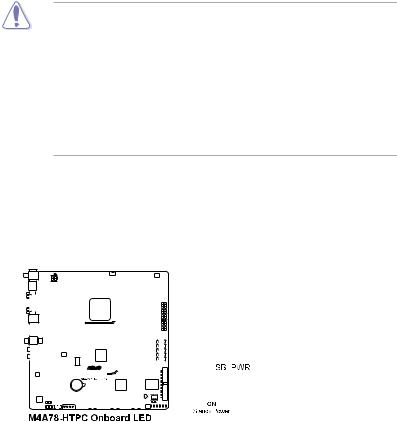
Onboard LED
The motherboard comes with a standby power LED that lights up to indicate that the system is ON, in sleep mode, or in soft-off mode. This is a reminder that you should shut down
the system and unplug the power cable before removing or plugging in any motherboard component. The illustration below shows the location of the onboard LED.
|
|
|
|
|
|
|
|
|
|
|
|
|
|
|
|
|
|
|
|
|
|
|
|
|
|
|
|
|
|
|
|
|
|
|
|
|
|
|
|
|
|
|
|
|
|
|
|
|
|
|
|
|
|
|
|
|
|
|
|
|
|
|
|
|
|
|
|
|
|
|
|
|
|
|
|
|
|
|
|
|
|
|
|
|
|
|
|
|
|
|
|
|
|
|
|
|
|
|
|
|
|
|
|
|
|
|
|
|
|
|
|
|
|
|
|
|
|
|
|
|
|
|
|
|
|
|
|
|
|
|
|
|
|
|
|
|
|
|
|
|
|
|
|
|
|
|
|
|
|
|
|
|
|
|
|
|
|
|
|
|
|
|
|
|
|
|
|
|
|
|
|
|
|
|
|
|
|
|
|
|
|
|
|
|
|
|
|
|
|
|
|
|
|
|
|
|
|
|
|
|
|
|
|
|
|
|
|
|
|
|
|
|
|
|
|
|
|
|
|
|
|
|
|
|
|
|
|
|
|
|
|
|
|
|
|
|
|
|
|
|
|
|
|
|
|
|
|
|
|
|
|
|
|
|
|
|
|
|
|
|
|
|
|
|
|
|
|
|
|
|
|
|
|
|
|
|
|
|
|
|
|
|
|
|
|
|
|
|
|
|
|
|
|
|
|
|
|
|
|
|
|
|
|
|
|
|
|
|
|
|
|
|
|
|
|
|
|
|
|
|
|
|
|
|
|
|
|
|
|
|
|
|
|
|
|
|
|
|
|
|
|
|
|
|
|
|
|
|
|
|
|
|
|
|
|
|
|
|
|
|
|
|
|
|
|
|
|
|
|
|
|
|
|
|
|
|
|
|
|
|
|
|
|
|
|
|
|
|
|
|
|
|
|
|
|
|
|
|
|
|
|
|
|
|
|
|
|
|
|
|
|
|
|
|
|
|
|
|
|
|
|
|
|
|
|
|
|
|
|
|
|
|
|
|
|
|
|
|
|
|
|
|
|
|
|
|
|
|
|
|
|
|
|
|
|
|
|
|
|
|
|
|
|
|
|
|
|
|
|
|
|
|
|
|
|
|
|
|
|
|
|
|
|
|
|
|
|
|
|
|
|
|
|
|
|
|
|
|
|
|
|
|
|
|
|
|
|
|
|
|
|
|
|
|
|
|
|
|
|
|
|
|
|
|
|
|
|
|
|
|
|
|
|
|
|
|
|
|
|
|
|
|
|
|
|
|
|
|
|
|
|
|
|
|
|
|
|
|
|
|
|
|
|
|
|
|
|
|
|
|
|
|
|
|
|
|
|
|
|
|
|
|
|
|
|
|
|
|
|
|
|
|
|
|
|
|
|
|
|
|
|
|
|
|
|
|
|
|
|
|
|
|
|
|
|
|
|
|
|
|
|
|
|
|
|
|
|
|
|
|
|
|
|
|
|
|
|
|
|
|
|
|
|
|
|
|
|
|
|
|
|
|
|
|
|
|
|
|
|
|
|
|
|
|
|
|
|
|
|
|
|
|
|
|
|
|
|
|
|
|
|
|
|
|
|
|
|
|
|
|
|
|
|
|
|
|
|
|
|
|
|
|
|
|
|
|
|
|
|
|
|
|
|
|
|
|
|
|
|
|
|
|
|
|
|
|
|
|
|
|
|
|
|
|
|
|
|
|
|
|
|
|
|
|
|
|
|
|
|
|
|
|
|
|
|
|
|
|
|
|
|
|
|
|
|
|
|
|
|
|
|
|
|
|
|
|
|
|
|
|
|
|
|
|
|
|
|
|
|
|
|
|
|
|
|
|
|
|
|
|
|
|
|
|
|
|
|
|
|
|
|
|
|
|
|
|
|
|
|
|
|
|
|
|
|
|
|
|
|
|
|
|
|
|
|
|
|
|
|
|
|
|
|
|
|
|
|
|
|
|
|
|
|
|
|
|
|
|
|
|
|
|
|
|
|
|
|
|
|
|
|
|
|
|
|
|
|
|
|
|
|
|
|
|
|
|
|
|
|
|
|
|
|
|
|
|
|
|
|
|
|
|
|
|
|
|
|
|
|
|
|
|
|
|
|
|
|
|
|
|
|
|
|
1-4 |
|
|
|
|
|
|
|
|
|
|
|
|
|
|
|
|
|
|
|
|
|
|
|
|
|
|
|
|
|
|
|
|
|
|
|
|
|
|
|
|
|
|
ASUS M4A78-HTPC |

1.5Motherboard overview
1.5.1Placement direction
When installing the motherboard, ensure that you place it into the chassis in the correct orientation. The edge with external ports goes to the rear part of the chassis as indicated in the image below.
1.5.2Screw holes
Place eight screws into the holes indicated by circles to secure the motherboard to the chassis.
Do not overtighten the screws! Doing so can damage the motherboard.
Place this side towards |
the rear of the chassis. |
|
|
|
|
|
|
|
|
|
|
|
|
|
|
|
|
|
|
|
|
|
|
|
|
|
|
|
|
|
|
|
|
|
|
|
|
|
|
|
|
|
|
|
|
|
|
|
|
|
|
|
|
|
|
|
|
|
|
|
|
|
|
|
|
|
|
|
|
|
|
|
|
|
|
|
|
|
|
|
|
|
|
|
|
|
|
|
|
|
|
|
|
|
|
|
|
|
|
|
|
|
|
|
|
|
|
|
|
|
|
|
|
|
|
|
|
|
|
|
|
|
|
|
|
|
|
|
|
|
|
|
|
|
|
|
|
|
|
|
|
|
|
|
|
|
|
|
|
|
|
|
|
|
|
|
|
|
|
|
|
|
|
|
|
|
|
|
|
|
|
|
|
|
|
|
|
|
|
|
|
|
|
|
|
|
|
|
|
|
|
|
|
|
|
|
|
|
|
|
|
|
|
|
|
|
|
|
|
|
|
|
|
|
|
|
|
|
|
|
|
|
|
|
|
|
|
|
|
|
|
|
|
|
|
|
|
|
|
|
|
|
|
|
|
|
|
|
|
|
|
|
|
|
|
|
|
|
|
|
|
|
|
|
|
|
|
|
|
|
|
|
|
|
|
|
|
|
|
|
|
|
|
|
|
|
|
|
|
|
|
|
|
|
|
|
|
|
|
|
|
|
|
|
|
|
|
|
|
|
|
|
|
|
|
|
|
|
|
|
|
|
|
|
|
|
|
|
|
|
|
|
|
|
|
|
|
|
|
|
|
|
|
|
|
|
|
|
|
|
|
|
|
|
|
|
|
|
|
|
|
|
|
|
|
|
|
|
|
|
|
|
|
|
|
|
|
|
|
|
|
|
|
|
|
|
|
|
|
|
|
|
|
|
|
|
|
|
|
|
|
|
|
|
|
|
|
|
|
|
|
|
|
|
|
|
|
|
|
|
|
|
|
|
|
|
|
|
|
|
|
|
|
|
|
|
|
|
|
|
|
|
|
|
|
|
|
|
|
Chapter 1: Product introduction |
1-5 |
||||||||||||||||||||||||||

1.5.3Motherboard layout
1.5.4Layout contents
Connectors/Jumpers/Slots |
Page |
|
1. |
ATX power connectors (24-pin EATXPWR, 4-pinATX12V) |
1-22 |
2. |
CPU socketAM2+/AM2 |
1-7 |
3. |
CPU, Chassis and Power Fan connectors (4-pin CPU_FAN, 3-pin CHA_FAN1–2, |
1-21 |
|
3-pin PWR_FAN) |
|
4. |
DDR2 DIMM slots |
1-10 |
5. |
Serial ATA connectors (7-pin SATA1-5) |
1-24 |
6. |
IDE connector (40-1 pin PRI_IDE) |
1-23 |
7. |
Onboard LED (SB_PWR) |
1-4 |
8. |
Clear RTC RAM (CLRTC) |
1-17 |
9. |
System panel connector (10-1 pin PANEL) |
1-25 |
10. |
USB connectors (10-1 pin USB56, USB78, USB910) |
1-26 |
11. |
Audio power connector (4-pin AUDIO_PWR) |
1-26 |
12. |
Optical drive audio in connector (4-pin CD) |
1-27 |
13. |
Front panel audio connector (10-1 pinAAFP) |
1-28 |
14. |
Digital audio connector (4-1 pin SPDIF_OUT) |
1-27 |
1-6 |
ASUS M4A78-HTPC |

1.6Central Processing Unit (CPU)
The motherboard comes with a CPU socket designed for AMD® AM3 Phenom™ II / Athlon™ X4 /Athlon™ X3 /Athlon™ X2 processors andAM2+ /AM2 Phenom™ X4 / Phenom™ X3 /Athlon™ X2 /Athlon™ / Sempron™ processors.
The CPU socket is not compatible with AMD® Opteron™ processors. Do not install an Opteron™ processor on this motherboard.
1.6.1Installing the CPU
To install a CPU:
1.Locate the CPU socket on the motherboard.
2. Press the lever sideways to unlock
the socket, then lift it up to a Socket lever
90°–100° angle.
Ensure that the socket lever is lifted up to 90°–100° angle, otherwise the CPU will not fit in completely.
3.Position the CPU above the socket such that the CPU corner with the gold triangle matches the socket corner with a small triangle.
4. Carefully insert the CPU into the socket until it fits in place.
The CPU fits only in one correct orientation. DO NOT force the CPU into the socket to prevent bending the pins and damaging the CPU!
Small triangle
Gold triangle |
Chapter 1: Product introduction |
1-7 |

5.When the CPU is in place, push down the socket lever to secure the CPU. The lever clicks on the side tab to indicate that it is locked.
6. Install a CPU heatsink and fan following the instructions that came with the heatsink package. You can also refer to section 1.6.2 Installing the heatsink and fan for instructions.
7. Connect the CPU fan cable to the CPU_FAN connector on the motherboard.
Do not forget to connect the CPU fan connector! Hardware monitoring errors can occur if you fail to plug this connector.
1.6.2Installing the heatsink and fan
Ensure that you use onlyAMD-certified heatsink and fan assembly.
To install the CPU heatsink and fan:
1.Place the heatsink on top of the installed CPU, making sure that the heatsink fits properly on the retention module base.
• The retention module base is already installed on the motherboard upon purchase.
• You do not have to remove the retention module base when installing the CPU or installing other motherboard components.
•If you purchased a separate CPU heatsink and fan assembly, ensure that a Thermal Interface Material is properly applied to the CPU heatsink or CPU before you install the heatsink and fan assembly.
CPU Fan
CPU Heatsink
Retention bracket
Retention Module Base
Retention bracket lock
1-8 |
ASUS M4A78-HTPC |
Your boxed CPU heatsink and fan assembly should come with installation instructions for the CPU, heatsink, and the retention mechanism. If the instructions in this section do not match the CPU documentation, follow the latter.
2.Attach one end of the retention bracket to the retention module base.
1
2
3 4
4 
 5
5
3.Align the other end of the retention bracket to the retention module base. A clicking sound denotes that the retention bracket is in place.
Ensure that the fan and heatsink assembly perfectly fits the retention mechanism module base, otherwise you cannot snap the retention bracket in place.
4.Push down the retention bracket lock on the retention mechanism to secure the heatsink and fan to the module base.
5.When the fan and heatsink assembly is in place, connect the CPU fan cable to the connector on the motherboard labeled CPU_FAN.
Do not forget to connect the CPU fan connector! Hardware monitoring errors can occur if you fail to plug this connector.
Chapter 1: Product introduction |
1-9 |
 Loading...