


M2N-L
Motherboard

E3333
First Edition
December 2007
Copyright © 2007 ASUSTeK COMPUTER INC. All Rights Reserved.
No part of this manual, including the products and software described in it, may be reproduced, transmitted, transcribed, stored in a retrieval system, or translated into any language in any form or by any means, except documentation kept by the purchaser for backup purposes, without the express written permission of ASUSTeK COMPUTER INC. (“ASUS”).
Product warranty or service will not be extended if: (1) the product is repaired, modified or altered, unless such repair, modification of alteration is authorized in writing byASUS; or (2) the serial number of the product is defaced or missing.
ASUS PROVIDES THIS MANUAL “AS IS” WITHOUT WARRANTY OF ANY KIND, EITHER EXPRESS OR IMPLIED, INCLUDING BUT NOT LIMITED TO THE IMPLIED WARRANTIES OR CONDITIONS OF MERCHANTABILITY OR FITNESS FOR A PARTICULAR PURPOSE. IN NO EVENT SHALL ASUS, ITS DIRECTORS, OFFICERS, EMPLOYEES OR AGENTS BE LIABLE FOR ANY INDIRECT, SPECIAL, INCIDENTAL, OR CONSEQUENTIAL DAMAGES (INCLUDING DAMAGES FOR LOSS OF PROFITS, LOSS OF BUSINESS, LOSS OF USE OR DATA, INTERRUPTION OF BUSINESS AND THE LIKE), EVEN IF ASUS HAS BEEN ADVISED OF THE POSSIBILITY OF SUCH DAMAGES ARISING FROM ANY DEFECT OR ERROR IN THIS MANUAL OR PRODUCT.
SPECIFICATIONS AND INFORMATION CONTAINED IN THIS MANUAL ARE FURNISHED FOR INFORMATIONAL USE ONLY, AND ARE SUBJECT TO CHANGE AT ANY TIME WITHOUT NOTICE, AND SHOULD NOT BE CONSTRUED AS A COMMITMENT BY ASUS. ASUS ASSUMES NO RESPONSIBILITY OR LIABILITY FOR ANY ERRORS OR INACCURACIES THAT MAY APPEAR IN THIS MANUAL, INCLUDING THE PRODUCTS AND SOFTWARE DESCRIBED IN IT.
Products and corporate names appearing in this manual may or may not be registered trademarks or copyrights of their respective companies, and are used only for identification or explanation and to the owners’ benefit, without intent to infringe.
ii

Contents
Notices......................................................................................................... |
vi |
Safety information...................................................................................... |
vii |
About this guide........................................................................................ |
viii |
M2N-L specifications summary.................................................................. |
x |
Chapter 1: Product introduction
1.1 |
Welcome!....................................................................................... |
1-1 |
|
1.2 |
Package contents......................................................................... |
1-1 |
|
1.3 |
Serial number label....................................................................... |
1-1 |
|
1.4 |
Special features............................................................................ |
1-2 |
|
|
1.4.1 |
Product highlights............................................................ |
1-2 |
|
1.4.2 |
ASUS Special features.................................................... |
1-3 |
Chapter 2: Hardware information
2.1 |
Before you proceed...................................................................... |
2-1 |
|
2.2 |
Motherboard overview................................................................. |
2-2 |
|
|
2.2.1 |
Placement direction ......................................................... |
2-2 |
|
2.2.2 |
Screw holes ..................................................................... |
2-2 |
|
2.2.3 |
Motherboard layout .......................................................... |
2-4 |
|
2.2.4 |
Layout contents . .............................................................. |
2-5 |
2.3 |
Central Processing Unit (CPU).................................................... |
2-6 |
|
|
2.3.1 |
Installing the CPU ............................................................ |
2-6 |
|
2.3.2 |
Installing the heatsink and fan ......................................... |
2-8 |
2.4 |
System memory.......................................................................... |
2-11 |
|
|
2.4.1 |
Overview ......................................................................... |
2-11 |
|
2.4.2 |
Memory configurations . .................................................. |
2-11 |
|
2.4.3 |
Installing a DIMM ........................................................... |
2-12 |
|
2.4.4 |
Removing a DIMM ......................................................... |
2-12 |
2.5 |
Expansion slots.......................................................................... |
2-13 |
|
|
2.5.1 |
Installing an expansion card .......................................... |
2-13 |
|
2.5.2 |
Configuring an expansion card ...................................... |
2-13 |
|
2.5.3 |
Interrupt assignments .................................................... |
2-14 |
|
2.5.4 |
PCI Express x16 slot . .................................................... |
2-14 |
|
2.5.5 |
PCI Express x1 slot . ...................................................... |
2-15 |
|
2.5.6 |
PCI slot .......................................................................... |
2-15 |
2.6 |
Jumpers |
....................................................................................... |
2-16 |
2.7 |
Connectors.................................................................................. |
2-18 |
|
iii

Contents
|
2.7.1 |
Rear panel connectors.................................................. |
2-18 |
|
2.7.2 |
Internal connectors........................................................ |
2-19 |
Chapter 3: Powering up |
|
||
3.1 |
Starting up for the first time........................................................ |
3-1 |
|
3.2 |
Powering off the computer.......................................................... |
3-2 |
|
|
3.2.1 |
Using the OS shut down function.................................... |
3-2 |
|
3.2.2 |
Using the dual function power switch.............................. |
3-2 |
Chapter 4: BIOS setup |
|
||
4.1 |
Managing and updating your BIOS............................................. |
4-1 |
|
|
4.1.1 |
Creating a bootable floppy disk....................................... |
4-1 |
|
4.1.2 |
AFUDOS utility................................................................ |
4-2 |
|
4.1.3 |
ASUS CrashFree BIOS 2 utility....................................... |
4-5 |
4.2 |
BIOS setup program..................................................................... |
4-7 |
|
|
4.2.1 |
BIOS menu screen.......................................................... |
4-8 |
|
4.2.2 |
Menu bar......................................................................... |
4-8 |
|
4.2.3 |
Navigation keys............................................................... |
4-9 |
|
4.2.4 |
Menu items...................................................................... |
4-9 |
|
4.2.5 |
Sub-menu items.............................................................. |
4-9 |
|
4.2.6 |
Configuration fields.......................................................... |
4-9 |
|
4.2.7 |
Pop-up window................................................................ |
4-9 |
|
4.2.8 |
General help.................................................................... |
4-9 |
4.3 |
Main menu................................................................................... |
4-10 |
|
|
4.3.1 |
System Time.................................................................. |
4-10 |
|
4.3.2 |
System Date.................................................................. |
4-10 |
|
4.3.3 |
Legacy Diskette A ......................................................... |
4-10 |
|
4.3.4 |
Primary IDE Master/Slave, SATA1~6............................. |
4-11 |
|
4.3.5 |
IDE Configuration.......................................................... |
4-12 |
|
4.3.6 |
System Information........................................................ |
4-14 |
4.4 |
Advanced menu.......................................................................... |
4-15 |
|
|
4.4.1 |
CPU Configuration......................................................... |
4-15 |
|
4.4.2 |
Chipset.......................................................................... |
4-16 |
|
4.4.3 |
Onboard Devices Configuration.................................... |
4-21 |
|
4.4.4 |
PCI PnP......................................................................... |
4-23 |
|
4.4.5 |
MPS Configuration........................................................ |
4-24 |
|
4.4.6 |
USB Configuration......................................................... |
4-24 |
iv

Contents
|
4.4.7 |
RemoteAccess Configuration....................................... |
4-25 |
4.5 |
Power menu................................................................................ |
4-26 |
|
|
4.5.1 |
Suspend Mode ............................................................. |
4-26 |
|
4.5.2 |
ACPI 2.0 Support........................................................... |
4-26 |
|
4.5.3 |
ACPI APIC Support ...................................................... |
4-26 |
|
4.5.4 |
APM Configuration........................................................ |
4-27 |
|
4.5.5 |
Hardware Monitor.......................................................... |
4-28 |
4.6 |
Boot menu................................................................................... |
4-29 |
|
|
4.6.1 |
Boot Device Priority....................................................... |
4-29 |
|
4.6.2 |
Boot Settings Configuration........................................... |
4-30 |
|
4.6.3 |
Security.......................................................................... |
4-31 |
4.7 |
Exit menu..................................................................................... |
4-33 |
|
Chapter 5: Software support
5.1 |
Installing an operating system.................................................... |
5-1 |
|
5.2 |
Support CD information............................................................... |
5-1 |
|
|
5.2.1 |
Running the support CD.................................................. |
5-1 |
|
5.2.2 |
Drivers menu................................................................... |
5-2 |
|
5.2.3 |
Management Software menu.......................................... |
5-3 |
|
5.2.4 |
Utilities menu................................................................... |
5-4 |
|
5.2.5 |
ASUS Contact information............................................... |
5-5 |
|
5.2.6 |
Other information............................................................. |
5-5 |
5.3 |
Software information.................................................................... |
5-7 |
|
|
Cool ‘n’ Quiet!™ Technology.......................................................... |
5-7 |
|
5.4 |
RAID configurations..................................................................... |
5-8 |
|
|
Installing hard disks........................................................................ |
5-9 |
|
5.5 |
NVIDIA® RAID configurations.................................................... |
5-10 |
|
|
5.5.1 |
Entering the NVIDIA® RAID Utility ................................ |
5-10 |
|
5.5.2 |
Creating a RAID Volume ............................................... |
5-11 |
|
5.5.3 |
Rebuilding a RAID set................................................... |
5-13 |
|
5.5.4 |
Deleting a RAID array.................................................... |
5-15 |
|
5.5.5 |
Clearing the MBR.......................................................... |
5-16 |
5.6 |
Creating a RAID driver disk....................................................... |
5-17 |
|
Appendix: Reference information
M2N-L block diagram................................................................... |
A-1 |

Notices
Federal Communications Commission Statement
This device complies with Part 15 of the FCC Rules. Operation is subject to the following two conditions:
•This device may not cause harmful interference, and
•This device must accept any interference received including interference that may cause undesired operation.
This equipment has been tested and found to comply with the limits for a Class B digital device, pursuant to Part 15 of the FCC Rules. These limits are designed to provide reasonable protection against harmful interference in a residential installation. This equipment generates, uses and can radiate radio
frequency energy and, if not installed and used in accordance with manufacturer’s instructions, may cause harmful interference to radio communications. However, there is no guarantee that interference will not occur in a particular installation. If this equipment does cause harmful interference to radio or television reception, which can be determined by turning the equipment off and on, the user is encouraged to try to correct the interference by one or more of the following measures:
•Reorient or relocate the receiving antenna.
•Increase the separation between the equipment and receiver.
•Connect the equipment to an outlet on a circuit different from that to which the receiver is connected.
•Consult the dealer or an experienced radio/TV technician for help.
The use of shielded cables for connection of the monitor to the graphics card is required to assure compliance with FCC regulations. Changes or modifications to this unit not expressly approved by the party responsible for compliance could void the user’s authority to operate this equipment.
Canadian Department of Communications Statement
This digital apparatus does not exceed the Class B limits for radio noise emissions from digital apparatus set out in the Radio Interference Regulations of the Canadian Department of Communications.
This class B digital apparatus complies with Canadian ICES-003.
vi

Safety information
Electrical safety
•To prevent electrical shock hazard, disconnect the power cable from the electrical outlet before relocating the system.
•When adding or removing devices to or from the system, ensure that the power cables for the devices are unplugged before the signal cables are connected. If possible, disconnect all power cables from the existing system before you add a device.
•Before connecting or removing signal cables from the motherboard, ensure that all power cables are unplugged.
•Seek professional assistance before using an adpater or extension cord. These devices could interrupt the grounding circuit.
•Make sure that your power supply is set to the correct voltage in your area. If you are not sure about the voltage of the electrical outlet you are using, contact your local power company.
•If the power supply is broken, do not try to fix it by yourself. Contact a qualified service technician or your retailer.
Operation safety
•Before installing the motherboard and adding devices on it, carefully read all the manuals that came with the package.
•Before using the product, make sure all cables are correctly connected and the power cables are not damaged. If you detect any damage, contact your dealer immediately.
•To avoid short circuits, keep paper clips, screws, and staples away from connectors, slots, sockets and circuitry.
•Avoid dust, humidity, and temperature extremes. Do not place the product in any area where it may become wet.
•Place the product on a stable surface.
•If you encounter technical problems with the product, contact a qualified service technician or your retailer.
This symbol of the crossed out wheeled bin indicates that the product (electrical and electronic equipment, Mercury-containing button cell battery) should not be placed in municipal waste. Check local regulations for disposal of electronic products.
vii

About this guide
This user guide contains the information you need when installing and configuring the motherboard.
How this guide is organized
This guide contains the following parts:
•Chapter 1: Product introduction
This chapter describes the features of the motherboard and the new technology it supports.
•Chapter 2: Hardware information
This chapter lists the hardware setup procedures that you have to perform when installing system components. It includes description of the switches, jumpers, and connectors on the motherboard.
•Chapter 3: Powering up
This chapter describes the power up sequence and ways of shutting down the system.
•Chapter 4: BIOS setup
This chapter tells how to change system settings through the BIOS Setup menus. Detailed descriptions of the BIOS parameters are also provided.
•Chapter 5: Software support
This chapter describes the contents of the support CD that comes with the motherboard package.
Where to find more information
Refer to the following sources for additional information and for product and software updates.
1.ASUS websites
The ASUS website provides updated information on ASUS hardware and software products. Refer to the ASUS contact information.
2.Optional documentation
Your product package may include optional documentation, such as warranty flyers, that may have been added by your dealer. These documents are not part of the standard package.
viii

Conventions used in this guide
To make sure that you perform certain tasks properly, take note of the following symbols used throughout this manual.
DANGER/WARNING: Information to prevent injury to yourself when trying to complete a task.
CAUTION: Information to prevent damage to the components when trying to complete a task.
IMPORTANT: Instructions that you MUST follow to complete a task.
NOTE: Tips and additional information to help you complete a task.
Typography
Bold text |
Indicates a menu or an item to select. |
Italics |
Used to emphasize a word or a phrase. |
<Key> |
Keys enclosed in the less-than and greater-than sign |
|
means that you must press the enclosed key. |
Example: <Enter> means that you must press the Enter or Return key.
<Key1>+<Key2>+<Key3> If you must press two or more keys simultaneously, the key names are connected with a plus sign (+).
Example: <Ctrl>+<Alt>+<D>
Command Means that you must type the command exactly as shown.
Example: At the DOS prompt, type the command line: format A:/S
ix
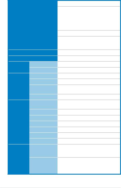
M2N-L specifications summary
Processor / System Bus
Core Logic
Form Factor
ASUS |
Smart Fan |
|
Features |
ASWM2.0 |
|
|
||
Memory |
Total Slots |
|
|
Capacity |
|
|
Memory Type |
|
|
Memory Size |
|
Expansion |
Total PCI/PCI-X/ |
|
Slots |
PCIe Slots |
|
(follow SSI |
Slot Location 1 |
|
Loacation #) |
||
Slot Location 2 |
||
|
||
|
Slot Location 3 |
|
|
Slot Location 4 |
|
|
Slot Location 5 |
|
|
Slot Location 6 |
|
Storage |
IDE Controller |
|
|
SATA Controller |
1 x Socket AM2 supports:
AMD Sempron™
AMD Athlon™ 64
AMD Athlon™ 64 X2
AMD Athlon™ 64 FX
AMD Opteron™ 64 1000 series (dual core) AMD Phenom™
Single Core/ Dual Core/Quad Core processor
HT Bus Link Speed: 2000 MT/s
AMD64 Technology
AMD Cool 'n' Quiet™ Technology
NVIDIA® nForce® 570 SLI MCP (MCP55P)
ATX, 12 in x 9.6 in (30.5 cm x 24.5 cm)
Smart Fan
4
Maximum up to 8GB
Unbuffered DIMM DDR2 800/667/533 ECC/
Non-ECC
128MB, 256 MB, 512 MB, 1 GB, 2GB
6
1 x PCI slot (33MHz/32-bit/3.3V/PCI2.2)
1 x PCI slot (33MHz/32-bit/3.3V/PCI2.2)
1 x PCI Express x16 slot (x8 link, PCIE4)
1 x PCI Express x1 slot (x1 link)
1 x PCI Express x1 slot (x1 link)
1 x PCI Express x16 slot (x16 link, PCIE1)
NVIDIA® nForce® 570 SLI MCP (MCP55P) - 1 x IDE connector for up to two Ultra DMA 133/100/66/33 devices
NVIDIA® nForce® 570 SLI MCP (MCP55P) - 6 x Serial ATA II 3.0 Gb/s devices with RAID 0, RAID 1, RAID 0+1, RAID 5, and
JBOD configurations
(continued on the next page)
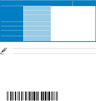
M2N-L specifications summary
Networking |
LAN |
Graphic |
VGA |
Onboard I/O |
Floppy Connector |
Connectors |
PSU Connectors |
|
|
|
USB Connectors |
|
Fan Headers |
|
Chassis Intruder |
|
Serial Port Header |
Rear I/O |
External Serial Port |
Connectors |
External USB ports |
|
|
|
VGA Port |
|
RJ-45 Port |
|
PS/2 KB/Mouse |
Management |
Software |
Solutions |
|
Monitoring |
CPU Temperature |
|
FAN RPM |
EMI |
US (FCC, CFR47 |
|
Part 15, Class B) |
|
Europe (CE, |
|
EN55022 & EN |
|
55024) |
Environment |
|
Dual Onboard Marvell® 8056 PCIe GbE LAN controllers
XGI® Volari™ Z9s VGA Controller / 32MB
DDR2 DRAM
1
24-pin ATX power connector + 4-pin ATX 12V power connector
1 (for 2 USB 2.0/1.1 ports)
4 x 3-pin (CPU_FAN1, FRNT_FAN1/2,
REAR_FAN1)
1
1
1
2 (Both support USB 2.0/1.1)
1
2
1 mouse port + 1 keyboard port
ASWM 2.0
Operating temperature: 10 oC ~ 35 oC Non operating temperature: -40 oC ~ 70 oC Non operating humidity: 20% ~ 90%
(Non condensing)
*Specifications are subject to change without notice.
xi

xii
This chapter describes the motherboard features and the new technologies
it supports.
Product1 introduction

|
Chapter summary |
1 |
|
|
|
||
|
|
|
|
|
|
|
|
1.1 |
Welcome!....................................................................................... |
1-1 |
1.2 |
Package contents......................................................................... |
1-1 |
1.3 |
Serial number label....................................................................... |
1-1 |
1.4 |
Special features............................................................................ |
1-2 |
ASUS M2N-L
1.1Welcome!
Thank you for buying an ASUS® M2N-L motherboard!
The motherboard delivers a host of new features and latest technologies, making it another standout in the long line of ASUS quality motherboards!
Before you start installing the motherboard, and hardware devices on it, check the items in your package with the list below.
1.2Package contents
Check your motherboard package for the following items.
Cables |
Serial ATA signal cable |
|
Serial ATA power cable |
|
2-in-1 Floppy/Ultra ATA |
|
disk drive cable |
Accessories |
I/O shield |
Application CD |
M2N-L support CD |
Documentation |
User guide |
MB Packing Quantity |
M2N-L motherboard |
MB Retail Pack |
MB Bulk Pack |
6 |
|
- |
|
3 |
- |
1 |
- |
|
|
1 |
10 |
1 |
10 |
1 |
10 |
|
|
1 piece per box |
10 pieces per carton |
|
|
If any of the above items is damaged or missing, contact your retailer.
1.3Serial number label
Before requesting support from the ASUS Technical Support team, you must take note of the motherboard's serial number containing 12 characters xxM0Axxxxxxx shown as the figure below. With the correct serial number of the product, ASUS
Technical Support team members can then offer a quicker and satisfying solution to your problems.
|
|
M2N-L |
Made |
|
in |
|
China |
|
|
ASUS M2N-L |
1- |
1.4Special features
1.4.1Product highlights
Latest processor technology 


The motherboard comes with a 940-pin AM2 socket that supports AMD Athlon™ 64 x2, AMD Athlon™ 64, AMD Athlon™ 64 FX, AMD Sempron™, AMD Opteron™ 64 1000 series (dual core), and AMD Phenom™ processors. With an integrated lowlatency high-bandwidth memory controller and a highly scalable HyperTransport™ technology-based system bus, the motherboard provides a powerful platform for your diverse computing needs, increased office productivity, and enhanced digital media experience.
It provides extremely high performances and shortened data access time by supporting 2000 MT/s HyperTransport Bus, dual-channel un-buffered DDR2 800 memory and AMD Cool ‘n’ Quiet Technology. See page 2-6 for details.
DDR2 memory support 

The motherboard supports DDR2 memory that features data transfer rates of
800/667/533 MHz to meet the higher bandwidth requirements of the latest
3D graphics, multimedia, and Internet applications. The dual-channel DDR2 architecture doubles the bandwidth of your system memory to boost system performance, eliminating bottlenecks with peak bandwidths of up to 12.8 GB/s.
PCI Express™ interface
The motherboard fully supports PCI Express, the latest I/O interconnect technology that speeds up the PCI bus. PCI Express features point topoint serial interconnections between devices and allows higher clockspeeds by carrying data in packets. This high speed interface is software compatible with existing PCI specifications.
RAID solution
Onboard RAID controllers allow you to select the best RAID solution using Serial ATA devices.
The NVIDIA® nForce® 570 SLI MCP (MCP55P) chipset allows RAID 0, RAID 1,
RAID 5, RAID 0+1, and JBOD configurations for six SATAdisks.
Serial ATA 3Gb/s technology 
The motherboard supports the next-generation Serial ATA II 3Gb/s technology through the Serial ATA interfaces and the NVIDIA® nForce® 570 SLI MCP
(MCP55P) chipset. The SerialATA3Gb/s specification provides twice the bandwidth of the current Serial ATA products. Additionally, Serial ATA allows for thinner, more flexible cables with lower pin count and reduced voltage required.
1- |
Chapter 1: Product introduction |

USB 2.0 technology
The motherboard implements the Universal Serial Bus (USB) 2.0 specification, dramatically increasing the connection speed from the 12 Mbps bandwidth on USB 1.1 to a fast 480 Mbps on USB 2.0. USB 2.0 is backward compatible with USB 1.1.
Dual Gigabit LAN solution
The motherboard comes with dual Gigabit LAN controllers to provide the total solution for your networking needs. These network controllers use the PCI Express segment to provide faster data bandwidth for your wired or wireless Internet, LAN, and file sharing requirements.
AMD Cool ‘n’ Quiet Technology
The motherboard supports the AMD Cool ‘n’ Quiet Technology, which monitors system operation and automatically adjusts CPU voltage and frequency for a cool and quiet operating environment.
1.4.2ASUS Special features
ASUS CrashFree BIOS 2 
ThisfeatureallowsyoutorestoretheoriginalBIOSdatafroma bootable floppy disk containing the BIOS file incasewhentheBIOScodesanddataarecorrupted.This protection eliminates the need to buy a replacement ROM chip.
ASUS Smart Fan technology 
The ASUS Smart Fan technology smartly adjusts the fan speeds according to the system loading to ensure quiet, cool, and efficient operation.
ASUS M2N-L |
1- |

1- |
Chapter 1: Product introduction |
This chapter lists the hardware setup procedures that you have to perform when installing system components. It includes description of the jumpers and connectors on the motherboard.
Hardware2 information

|
Chapter summary |
2 |
|
|
|
||
|
|
|
|
|
|
|
|
2.1 |
Before you proceed...................................................................... |
2-1 |
2.2 |
Motherboard overview................................................................. |
2-2 |
2.3 |
Central Processing Unit (CPU).................................................... |
2-6 |
2.4 |
System memory.......................................................................... |
2-11 |
2.5 |
Expansion slots.......................................................................... |
2-13 |
2.6 |
Jumpers....................................................................................... |
2-16 |
2.7 |
Connectors.................................................................................. |
2-18 |
ASUS M2N-L
2.1Before you proceed
Take note of the following precautions before you install motherboard components or change any motherboard settings.
•Unplug the power cord from the wall socket before touching any component.
•Use a grounded wrist strap or touch a safely grounded object or to a metal object, such as the power supply case, before handling components to avoid damaging them due to static electricity.
•Hold components by the edges to avoid touching the ICs on them.
•Whenever you uninstall any component, place it on a grounded antistatic pad or in the bag that came with the component.
•Before you install or remove any component, ensure
that the ATX power supply is switched off or the power cord is detached from the power supply. Failure to do so may cause severe damage to the motherboard, peripherals, and/or components.
Onboard LED
The motherboard comes with a standby power LED. The green LED lights up to indicate that the system is ON, in sleep mode, or in soft off mode. This is a reminder that you should shut down the system and unplug the power cable before removing or plugging in any motherboard component. The illustration below shows the location of the onboard LED.
|
SB_PWR1 |
|
M2N-L |
ON |
OFF |
|
Standby |
Powered |
M2N-L Onboard LED |
Power |
Off |
|
|
|
ASUS M2N-L |
2- |
2.2Motherboard overview
Before you install the motherboard, study the configuration of your chassis to ensure that the motherboard fits into it.
Make sure to unplug the power cord before installing or removing the motherboard. Failure to do so can cause you physical injury and damage motherboard components.
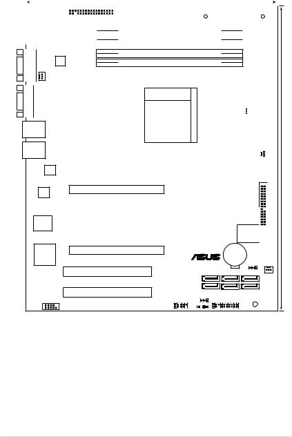
2.2.1Placement direction
When installing the motherboard, make sure that you place it into the chassis in the correct orientation. The edge with external ports goes to the rear part of the chassis as indicated in the image below.
2.2.2Screw holes
Place nine (9) screws into the holes indicated by circles to secure the motherboard to the chassis. Refer to the illustration on the next page.
Do not overtighten the screws! Doing so can damage the motherboard.
2- |
Chapter 2: Hardware information |
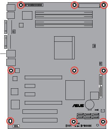
Place this side towards the rear of the chassis
PRI IDE1 |
® |
M2N-L |
ASUS M2N-L |
2- |
2.2.3Motherboard layout
|
|
|
|
|
|
|
|
|
|
|
24.5cm (9.6in) |
|
|
|
||
|
|
|
|
|
|
|
|
|
|
|
|
|
|
|
|
|
PS/2KBMS |
|
|
|
|
|
|
ATXPWR1 |
|
|
|
||||||
T: Mouse |
|
|
|
|
FLOPPY1 |
|
|
|
|
|||||||
|
|
|
|
|
|
|
||||||||||
B: Keyboard |
|
|
|
|
|
|
|
|
|
|
|
|||||
|
USB12 |
|
|
|
SuperI/O |
|
|
DDR2 DIMM_A2 (64 bit,240-pin module) |
|
|
|
|
||||
|
|
|
|
|
|
|
|
|
|
|
||||||
|
DDR2 DIMM_A1 (64 bit,240-pin module) |
|
|
|
|
|||||||||||
|
|
|
|
|
|
|
|
|
|
|
|
|
|
|
||
|
|
|
|
|
|
|
|
|
|
|
|
|
|
|
|
|
|
|
|
|
|
|
|
|
|
|
|
|
|
|
|
|
|
COM1 |
FAN1 |
|
REAR_ |
VGA1 |
|
DDR2 DIMM_B2 (64 bit,240-pin module)
DDR2 DIMM_B1 (64 bit,240-pin module)
ATX12V1
Socket AM2
 CPU_FAN1
LAN1
LAN2
Marvell
8056
FRNT FAN2 |
(12in) |
|
|
|
30.5cm |
|
|
|
|
|
|
|
|
|
Marvell
8056
PCIE1
|
|
|
PCIE2 |
|
NVIDIA |
|
|
|
|
|
NF570 SLI |
PCIE3 |
|
|
|
|
|
|
|
|
8Mb BIOS


 PRI_IDE1
XGI |
PCIE4 |
® |
CR2032 3V |
|
|
|
Lithium Cell |
|
|||
Z9s |
M2N-L |
CMOS Power |
|
||
|
|
||||
|
|
CLRTC1 |
|
||
|
|
|
|
|
|
|
PCI5 |
SATA1 |
SATA3 |
SATA5 |
FRNT_FAN1 |
|
PCI6 |
SATA2 |
SATA4 |
SATA6 |
|
|
|
RECOVERY1 |
|
|
|
|
USB34 |
CHASSIS1 PANEL1 |
|
|
|
|
COM2 |
|
|
SB_PWR1 |
|
2- |
Chapter 2: Hardware information |

2.2.4Layout contents
Slots |
Page |
|
1. |
CPU sockets |
2-6 |
2. |
DDR2 DIMM sockets |
2-12 |
3. |
PCI Express x16 slot |
2-14 |
4. |
PCI Express x1 slot |
2-15 |
5. |
PCI slot |
2-15 |
Jumper |
Page |
|
1. |
Clear RTC RAM (CLRTC1) |
2-16 |
2. |
BIOS Recovery |
2-17 |
|
|
|
Rear panel connectors |
Page |
|
1. |
PS/2 mouse port (green) |
2-18 |
2. |
LAN 1 (RJ-45) port |
2-18 |
3. |
LAN 2 (RJ-45) port |
2-18 |
4. VGA port |
2-18 |
|
5. |
Serial (COM1) port |
2-18 |
6. USB 2.0 ports 1 and 2 |
2-18 |
|
7. |
PS/2 keyboard port (purple) |
2-18 |
|
|
|
Internal connectors |
Page |
|
1. |
Floppy disk drive connector (34-1 pin FLOPPY) |
2-19 |
2. |
IDE connector (40-1 pin PRI_IDE) |
2-19 |
3. |
Serial ATA connectors (7-pin SATA1, SATA2, SATA3, SATA4, SATA5, |
2-20 |
|
SATA6) |
|
4. |
CPU fan, Front fan, and Rear fan connectors |
2-21 |
|
(CPU_FAN1, FRONT_FAN1/2, REAR_FAN1) |
|
5. |
USB connector (10-1 pin USB34) |
2-21 |
6. |
Serial port connector (10-1 pin COM2) |
2-22 |
7. |
ATX power connectors (24-pin ATXPWR1, 4-pin ATX12V1) |
2-23 |
8. |
System panel connector (20-1 pin PANEL1) |
2-24 |
ASUS M2N-L |
2- |
2.3Central Processing Unit (CPU)
The motherboard comes with a 940-pin AM2 socket designed for AMD Athlon™ 64 X2, AMD Athlon™ 64, AMD Athlon™ 64 FX, AMD Sempron™, AMD Opteron™ 64 1000 series (dual core), and AMD Phenom™ processors.
The AM2 socket has a different pin layout from the 940-pin socket designed for the AMD Opteron™ 200/800 series processor. Make sure you use a CPU designed for theAM2 socket. The CPU fits in only one correct orientation. DO
NOT force the CPU into the socket to prevent bending the connectors on the socket and damaging the CPU!
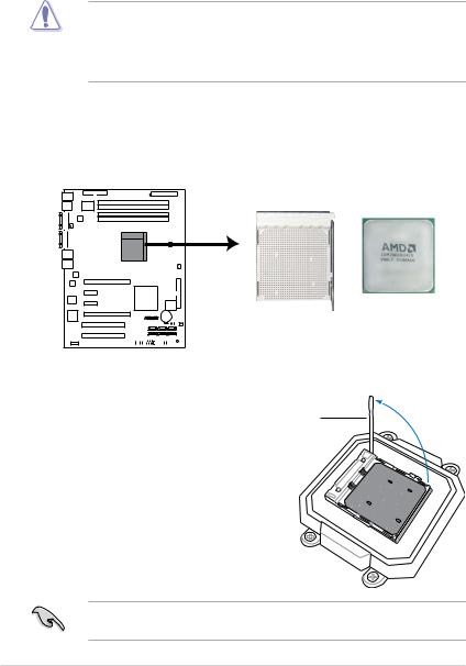
2.3.1Installing the CPU
To install a CPU:
1.Locate the CPU socket on the motherboard.
M2N-L |
M2N-L CPU Socket AM2 |
2. |
Unlock the socket by pressing the |
|
|
lever sideways, then lift it up to a |
Socket lever |
|
90º angle. |
|
Make sure that the socket lever is lifted up to a 90º angle; otherwise, the CPU will not fit in completely.
2- |
Chapter 2: Hardware information |
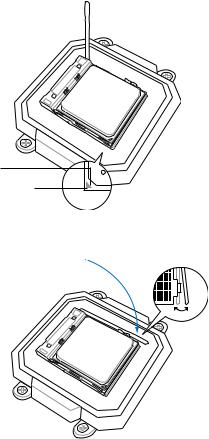
3.Position the CPU above the socket such that the CPU corner with the gold triangle matches the socket corner with a small triangle.
4. Carefully insert the CPU into the socket until it fits in place.
Gold triangle
Small triangle
5.When the CPU is in place, push down the socket lever to secure the CPU. The lever clicks on the side tab to indicate that it is locked.
6.Install a CPU heatsink and fan following the instructions that came with the heatsink package.
ASUS M2N-L |
2- |
2.3.2Installing the heatsink and fan
The AMD Athlon™ 64 X2, AMD Athlon™ 64, AMD Athlon™ 64 FX, AMD Sempron™, AMD Opteron™ 64 1000 series (dual core), and AMD Phenom™ processors require a specially designed heatsink and fan assembly to ensure optimum thermal condition and performance.
Make sure that you use onlyAMD-certified heatsink and fan assembly.
To install the CPU heatsink and fan:
1.Place the heatsink on top of the installed CPU, making sure that the heatsink fits properly on the retention module base.
• The retention module base is already installed on the motherboard upon purchase.
•You do not have to remove the retention module base when installing the CPU or installing other motherboard components.
•If you purchased a separate CPU heatsink and fan assembly, make sure that a Thermal Interface Material is properly applied to the CPU heatsink or CPU before you install the heatsink and fan assembly.
Retention bracket
Retention module base
Your boxed CPU heatsink and fan assembly should come with installation instructions for the CPU, heatsink, and the retention mechanism. If the instructions in this section do not match the CPU documentation, follow the latter.
2- |
Chapter 2: Hardware information |

2.Attach one end of the retention bracket to the retention module base.
3.Align the other end of the retention bracket (near the retention bracket lock) to the retention module base. A clicking sound denotes that the retention bracket is in place.
Make sure that the fan and heatsink assembly perfectly fits the retention mechanism module base, otherwise you cannot snap the retention bracket in place.
4.Push down the retention bracket lock on the retention mechanism to secure the heatsink and fan to the module base.
ASUS M2N-L |
2- |
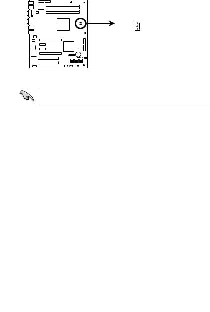
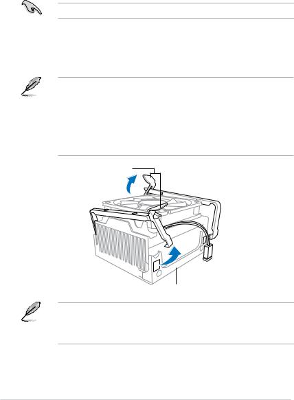
5.When the fan and heatsink assembly is in place, connect the CPU fan cable to the connector on the motherboard labeled CPU_FAN1.
CPU_FAN1
TACHO  +12V GND
M2N-L |
M2N-L CPU Fan Connector
•Do not forget to connect the CPU fan connector! Hardware monitoring errors can occur if you fail to plug this connector.
2-10 |
Chapter 2: Hardware information |
 Loading...