


M2N-E
Motherboard

E2630
First Edition
May 2006
Copyright © 2006 ASUSTeK COMPUTER INC. All Rights Reserved.
No part of this manual, including the products and software described in it, may be reproduced, transmitted, transcribed, stored in a retrieval system, or translated into any language in any form or by any means, except documentation kept by the purchaser for backup purposes, without the express written permission of ASUSTeK COMPUTER INC. (“ASUS”).
Product warranty or service will not be extended if: (1) the product is repaired, modified or altered, unless such repair, modification of alteration is authorized in writing by ASUS; or (2) the serial number of the product is defaced or missing.
ASUS PROVIDES THIS MANUAL “AS IS” WITHOUT WARRANTY OF ANY KIND, EITHER EXPRESS OR IMPLIED, INCLUDING BUT NOT LIMITED TO THE IMPLIED WARRANTIES OR CONDITIONS OF MERCHANTABILITY OR FITNESS FOR A PARTICULAR PURPOSE. IN NO EVENT SHALL ASUS, ITS DIRECTORS, OFFICERS, EMPLOYEES OR AGENTS BE LIABLE FOR ANY INDIRECT, SPECIAL, INCIDENTAL, OR CONSEQUENTIAL DAMAGES (INCLUDING DAMAGES FOR LOSS OF PROFITS, LOSS OF BUSINESS, LOSS OF USE OR DATA, INTERRUPTION OF BUSINESS AND THE LIKE), EVEN IF ASUS HAS BEEN ADVISED OF THE POSSIBILITY OF SUCH DAMAGES ARISING FROM ANY DEFECT OR ERROR IN THIS MANUAL OR PRODUCT.
SPECIFICATIONS AND INFORMATION CONTAINED IN THIS MANUAL ARE FURNISHED FOR INFORMATIONAL USE ONLY, AND ARE SUBJECT TO CHANGE AT ANY TIME WITHOUT NOTICE, AND SHOULD NOT BE CONSTRUED AS A COMMITMENT BY ASUS. ASUS ASSUMES NO RESPONSIBILITY OR LIABILITY FOR ANY ERRORS OR INACCURACIES THAT MAY APPEAR IN THIS MANUAL, INCLUDING THE PRODUCTS AND SOFTWARE DESCRIBED IN IT.
Products and corporate names appearing in this manual may or may not be registered trademarks or copyrights of their respective companies, and are used only for identification or explanation and to the owners’ benefit, without intent to infringe.
ii

Contents
Notices........................................................................................................ |
vii |
Safety information..................................................................................... |
viii |
About this guide.......................................................................................... |
ix |
M2N-E specifications summary................................................................. |
xi |
Chapter 1: Product introduction
1.1 |
Welcome!....................................................................................... |
1-1 |
|
1.2 |
Package contents......................................................................... |
1-1 |
|
1.3 |
Special features............................................................................ |
1-2 |
|
|
1.3.1 |
Product highlights............................................................ |
1-2 |
|
1.3.2 |
ASUS AI Lifestyle features ............................................. |
1-4 |
|
1.3.3 |
ASUS Special features.................................................... |
1-5 |
|
1.3.4 |
ASUS Intelligent Overclocking features........................... |
1-6 |
Chapter 2: Hardware information
2.1 |
Before you proceed...................................................................... |
2-1 |
|
2.2 |
Motherboard overview................................................................. |
2-2 |
|
|
2.2.1 |
Placement direction......................................................... |
2-2 |
|
2.2.2 |
Screw holes..................................................................... |
2-2 |
|
2.2.3 |
Motherboard layout.......................................................... |
2-3 |
|
2.2.4 |
Layout contents............................................................... |
2-4 |
2.3 |
Central Processing Unit (CPU).................................................... |
2-6 |
|
|
2.3.1 |
Installing the CPU............................................................ |
2-6 |
|
2.3.2 |
Installing the heatsink and fan......................................... |
2-8 |
2.4 |
System memory.......................................................................... |
2-11 |
|
|
2.4.1 |
Overview......................................................................... |
2-11 |
|
2.4.2 |
Memory configurations................................................... |
2-11 |
|
2.4.3 |
Installing a DIMM........................................................... |
2-15 |
|
2.4.4 |
Removing a DIMM......................................................... |
2-15 |
2.5 |
Expansion slots.......................................................................... |
2-16 |
|
|
2.5.1 |
Installing an expansion card.......................................... |
2-16 |
|
2.5.2 |
Configuring an expansion card...................................... |
2-16 |
|
2.5.3 |
Interrupt assignments.................................................... |
2-17 |
|
2.5.4 |
PCI slots........................................................................ |
2-17 |
|
2.5.5 |
PCI Express x1 slot....................................................... |
2-18 |
|
2.5.6 |
PCI Express x16 slots................................................... |
2-18 |
iii

Contents
2.6 |
Jumper |
......................................................................................... |
2-19 |
2.7 |
Connectors.................................................................................. |
2-20 |
|
|
2.7.1 .................................................. |
Rear panel connectors |
2-20 |
|
2.7.2 ........................................................ |
Internal connectors |
2-21 |
Chapter 3: Powering up
3.1 |
Starting up for the first time........................................................ |
3-1 |
|
3.2 |
Powering off the computer.......................................................... |
3-2 |
|
|
3.2.1 |
Using the OS shut down function.................................... |
3-2 |
|
3.2.2 |
Using the dual function power switch.............................. |
3-2 |
Chapter 4: BIOS setup
4.1 |
Managing and updating your BIOS............................................. |
4-1 |
|
|
4.1.1 |
ASUS Update utility......................................................... |
4-1 |
|
4.1.2 |
Creating a bootable floppy disk....................................... |
4-4 |
|
4.1.3 |
ASUS EZ Flash 2 utility................................................... |
4-5 |
|
4.1.4 |
Updating the BIOS........................................................... |
4-6 |
|
4.1.5 |
Saving the current BIOS file............................................ |
4-8 |
|
4.1.6 |
ASUS CrashFree BIOS 3 utility....................................... |
4-9 |
4.2 |
BIOS setup program................................................................... |
4-10 |
|
|
4.2.1 |
BIOS menu screen......................................................... |
4-11 |
|
4.2.2 |
Menu bar........................................................................ |
4-11 |
|
4.2.3 |
Legend bar.................................................................... |
4-12 |
|
4.2.4 |
Menu items.................................................................... |
4-12 |
|
4.2.5 |
Sub-menu items............................................................ |
4-12 |
|
4.2.6 |
Configuration fields........................................................ |
4-12 |
|
4.2.7 |
Pop-up window.............................................................. |
4-13 |
|
4.2.8 |
General help.................................................................. |
4-13 |
4.3 |
Main menu................................................................................... |
4-14 |
|
|
4.3.1 |
System Time.................................................................. |
4-14 |
|
4.3.2 |
System Date.................................................................. |
4-14 |
|
4.3.3 |
Legacy Diskette A.......................................................... |
4-14 |
|
4.3.4 |
Primary IDE Master/Slave............................................. |
4-15 |
|
4.3.5 |
SATA 1, 2, 3, 4, 5, 6....................................................... |
4-17 |
|
4.3.6 |
HDD SMART Monitoring................................................ |
4-18 |
|
4.3.7 |
Installed Memory........................................................... |
4-18 |
iv
Contents
|
4.3.8 |
Usable Memory............................................................. |
4-18 |
4.4 |
Advanced menu.......................................................................... |
4-19 |
|
|
4.4.1 |
JumperFree Configuration............................................. |
4-19 |
|
4.4.2 |
AI NET2......................................................................... |
4-22 |
|
4.4.3 |
PEG Link Mode............................................................. |
4-22 |
|
4.4.4 |
CPU Configuration......................................................... |
4-23 |
|
4.4.5 |
Chipset.......................................................................... |
4-27 |
|
4.4.6 |
PCIPnP.......................................................................... |
4-28 |
|
4.4.7 |
Onboard Device Configuration...................................... |
4-29 |
4.5 |
Power menu................................................................................ |
4-32 |
|
|
4.5.1 |
ACPI Suspend Type...................................................... |
4-32 |
|
4.5.2 |
ACPI APIC Support....................................................... |
4-32 |
|
4.5.3 |
APM Configuration........................................................ |
4-33 |
|
2.5.4 |
Hardware Monitor.......................................................... |
4-35 |
4.6 |
Boot menu................................................................................... |
4-37 |
|
|
4.6.1 |
Boot Device Priority....................................................... |
4-37 |
|
4.6.2 |
Removable Drives......................................................... |
4-38 |
|
4.6.3 |
Hard Disk Drives............................................................ |
4-38 |
|
4.6.4 |
CDROM Drives.............................................................. |
4-38 |
|
4.6.5 |
Boot Settings Configuration .......................................... |
4-39 |
|
4.6.6 |
Security.......................................................................... |
4-40 |
4.7 |
Tools menu.................................................................................. |
4-42 |
|
|
4.7.1 |
ASUS Music Alarm........................................................ |
4-42 |
|
4.7.2 |
ASUS O.C. Profile......................................................... |
4-44 |
|
4.7.3 |
ASUS EZ Flash 2.......................................................... |
4-46 |
4.8 |
Exit menu..................................................................................... |
4-47 |
|
Chapter 5: Software support
5.1 |
Installing an operating system.................................................... |
5-1 |
|
5.2 |
Support CD information............................................................... |
5-1 |
|
|
5.2.1 |
Running the support CD.................................................. |
5-1 |
|
5.2.2 |
Drivers menu................................................................... |
5-2 |
|
5.2.3 |
Utilities menu................................................................... |
5-3 |
|
5.2.4 |
Make Disk menu.............................................................. |
5-4 |
|
5.2.5 |
Manuals menu................................................................. |
5-5 |
|
5.2.6 |
ASUS Contact information............................................... |
5-6 |
|
|
|
|

Contents
|
5.2.7 |
Other information............................................................. |
5-6 |
5.3 |
Software information.................................................................... |
5-8 |
|
|
5.3.1 |
Cool ‘n’ Quiet!™ Technology........................................... |
5-8 |
|
5.3.2 |
ASUS PC Probe II......................................................... |
5-10 |
|
5.3.3 |
ASUS Music Alarm........................................................ |
5-16 |
|
5.3.4 |
ASUS AI Nap................................................................. |
5-19 |
|
5.3.5 |
ASUS AI Gear................................................................ |
5-20 |
|
5.3.6 |
SoundMAX® High Definition Audio utility....................... |
5-22 |
|
Audio Setup Wizard...................................................................... |
5-23 |
|
5.4 |
RAID configurations................................................................... |
5-26 |
|
|
5.4.1 |
Installing hard disks....................................................... |
5-27 |
|
5.4.2 |
NVIDIA® MediaShield RAID configurations................... |
5-28 |
5.5 |
Creating a RAID driver disk....................................................... |
5-35 |
|
vi

Notices
Federal Communications Commission Statement
This device complies with Part 15 of the FCC Rules. Operation is subject to the following two conditions:
•This device may not cause harmful interference, and
•This device must accept any interference received including interference that may cause undesired operation.
This equipment has been tested and found to comply with the limits for a Class B digital device, pursuant to Part 15 of the FCC Rules. These limits are designed to provide reasonable protection against harmful interference in a residential installation. This equipment generates, uses and can radiate radio
frequency energy and, if not installed and used in accordance with manufacturer’s instructions, may cause harmful interference to radio communications. However, there is no guarantee that interference will not occur in a particular installation. If this equipment does cause harmful interference to radio or television reception, which can be determined by turning the equipment off and on, the user is encouraged to try to correct the interference by one or more of the following measures:
•Reorient or relocate the receiving antenna.
•Increase the separation between the equipment and receiver.
•Connect the equipment to an outlet on a circuit different from that to which the receiver is connected.
•Consult the dealer or an experienced radio/TV technician for help.
The use of shielded cables for connection of the monitor to the graphics card is required to assure compliance with FCC regulations. Changes or modifications to this unit not expressly approved by the party responsible for compliance could void the user’s authority to operate this equipment.
Canadian Department of Communications Statement
This digital apparatus does not exceed the Class B limits for radio noise emissions from digital apparatus set out in the Radio Interference Regulations of the Canadian Department of Communications.
This class B digital apparatus complies with Canadian ICES-003.
vii
Safety information
Electrical safety
•To prevent electrical shock hazard, disconnect the power cable from the electrical outlet before relocating the system.
•When adding or removing devices to or from the system, ensure that the power cables for the devices are unplugged before the signal cables are connected. If possible, disconnect all power cables from the existing system before you add a device.
•Before connecting or removing signal cables from the motherboard, ensure that all power cables are unplugged.
•Seek professional assistance before using an adpater or extension cord. These devices could interrupt the grounding circuit.
•Make sure that your power supply is set to the correct voltage in your area. If you are not sure about the voltage of the electrical outlet you are using, contact your local power company.
•If the power supply is broken, do not try to fix it by yourself. Contact a qualified service technician or your retailer.
Operation safety
•Before installing the motherboard and adding devices on it, carefully read all the manuals that came with the package.
•Before using the product, make sure all cables are correctly connected and the power cables are not damaged. If you detect any damage, contact your dealer immediately.
•To avoid short circuits, keep paper clips, screws, and staples away from connectors, slots, sockets and circuitry.
•Avoid dust, humidity, and temperature extremes. Do not place the product in any area where it may become wet.
•Place the product on a stable surface.
•If you encounter technical problems with the product, contact a qualified service technician or your retailer.
This symbol of the crossed out wheeled bin indicates that the product (electrical and electronic equipment) should not be placed in municipal waste. Check local regulations for disposal of electronic products.
viii

About this guide
This user guide contains the information you need when installing and configuring the motherboard.
How this guide is organized
This guide contains the following parts:
•Chapter 1: Product introduction
This chapter describes the features of the motherboard and the new technology it supports.
•Chapter 2: Hardware information
This chapter lists the hardware setup procedures that you have to perform when installing system components. It includes description of the switches, jumpers, and connectors on the motherboard.
•Chapter 3: Powering up
This chapter describes the power up sequence and ways of shutting down the system.
•Chapter 4: BIOS setup
This chapter tells how to change system settings through the BIOS Setup menus. Detailed descriptions of the BIOS parameters are also provided.
•Chapter 5: Software support
This chapter describes the contents of the support CD that comes with the motherboard package.
•Chapter 6: NVIDIA® SLI™ Technology support
This chapter tells how to install SLI ready PCI Express graphics cards.
Where to find more information
Refer to the following sources for additional information and for product and software updates.
1.ASUS websites
The ASUS website provides updated information on ASUS hardware and software products. Refer to the ASUS contact information.
2.Optional documentation
Your product package may include optional documentation, such as warranty flyers, that may have been added by your dealer. These documents are not part of the standard package.
ix

Conventions used in this guide
To make sure that you perform certain tasks properly, take note of the following symbols used throughout this manual.
DANGER/WARNING: Information to prevent injury to yourself when trying to complete a task.
CAUTION: Information to prevent damage to the components when trying to complete a task.
IMPORTANT: Instructions that you MUST follow to complete a task.
NOTE: Tips and additional information to help you complete a task.
Typography
Bold text |
Indicates a menu or an item to select. |
Italics |
Used to emphasize a word or a phrase. |
<Key> |
Keys enclosed in the less-than and greater-than sign |
|
means that you must press the enclosed key. |
|
Example: <Enter> means that you must press the |
|
Enter or Return key. |
<Key1>+<Key2>+<Key3> If you must press two or more keys simultaneously, the key names are connected with a plus sign (+).
|
Example: <Ctrl>+<Alt>+<D> |
Command |
Means that you must type the command exactly as |
|
shown. |
|
Example: At the DOS prompt, type the command line: |
|
format a: |
M2N-E specifications summary
CPU
Chipset
System bus
Memory
Expansion slots
Storage
High Definition Audio
USB
ASUS AI Lifestyle features
LAN
Socket AM2 for AMD Athlon™ 64 X2 /AMD Athlon™ 64 /AMD Athlon™ 64 FX/AMD Sempron™ processors
Supports AMD Cool ‘n’ Quiet™ Technology
AMD64 architecture enables simultaneous 32-bit and 64-bit computing
AMD Live!™ ready
NVIDIA® nForce® 570 Ultra™ MCP
2000 / 1600 MT/s
Dual-channel memory architecture
-4 x 240-pin DIMM sockets support unbuffered
ECC/non-ECC DDR2 800/667/533 MHz memory modules
-Supports up to 8 GB system memory
1 x PCI Express x16 slot
1 x PCI Express x4 slot
2 x PCI Express x1 slots
3 x PCI 2.2 slots
NVIDIA® nForce® 570 Ultra™ MCP supports:
-1 x IDE connector for up to two Ultra DMA 133/100/66/33 devices
-6 x Serial ATA 3.0 Gb/s connectors support six Serial ATA devices
-RAID 0, RAID1, RAID 0+1, RAID 5, and JBOD configurations spanning across Serial ATA drives via the onboard NVIDIA® MediaShield™ RAID controller
SoundMAX® ADI AD1988 8-channel CODEC Supports Jack-Sensing, Enumeration, Multi-Streaming,
and Jack-Retasking Technology Coaxial S/PDIF Out interfaces
Supports up to 10 USB 2.0/1.1 ports (six at mid-board, - four on the rear panel)
AI Nap
AI Gear
Advanced Thermal Design
-ASUS Fanless Design: Heat-pipe Thermal solution ASUS Crystal Sound
-Noise filter
NVIDIA® nForce® 570 Ultra™ MCP built-in Gigabit MAC with external Marvell® PHY
(continued on the next page)
xi

M2N-E specifications summary
ASUS Exclusive Overclocking features
Internal connectors
Special features
Intelligent overclocking tools:
-AI NOS™ (Non-delay Overclocking System)
-AI Overclocking (intelligent CPU frequency tuner)
-ASUS PEG Link
ASUS O.C. Profile: overclocking configuration-sharing tool
Precision Tweaker:
-vDIMM: 4-step DRAM voltage control
-vCore: Adjustable CPU voltage at 0.0125 V increment
-Stepless Frequency Selection(SFS) allows FSB tuning from 200 MHz up to 400 MHz at 1 MHz increment
-PCI Express frequency allows PCI Express x16
frequency tuning from 100 MHz to 200 MHz at 1 MHz increment
Overclocking protection:
- ASUS C.P.R. (CPU Parameter Recall) ASUS AI Booster Utility
3 x USB 2.0 connectors support six additional USB 2.0 ports
1 x Floppy disk drive connector
1 x IDE connector for two devices
6 x Serial ATA connectors
1 x CPU / 4 x Chassis / 1 x Power fan connectors
1 x ADH connector
1 x Parallel connector
1 x S/PDIF Out connector Chassis intrusion connector Front panel audio connector CD audio in connector 24-pin ATX power connector
4-pin ATX 12 V power connector System panel connector
ASUS EZ DIY:
-ASUS CrashFree BIOS 3
-ASUS EZ Flash 2 ASUS Music Alarm
(continued on the next page)
xii
M2N-E specifications summary
Rear panel
BIOS features
Manageability
Power requirements
Support CD contents
Form factor
1 x PS/2 keyboard port (purple)
1 x PS/2 mouse port (green)
1 x Serial (COM1) port
1 x Coaxial S/PDIF Out port
1 x LAN (RJ-45) ports
4 x USB 2.0/1.1 ports
8-channel audio ports
4 Mb AWARD BIOS, PnP, DMI 2.0, WfM2.0, SM BIOS 2.3
WOL by PME, WOR by PME, Chassis intrusion, PXE
ATX power supply with 24-pin and 4-pin 12V plugs ATX 12V 2.0 compliant
Device drivers
ASUS AI Booster
ASUS PC Probe II
ASUS Update
NVIDIA® MediaShield™ RAID
Anti-virus software (OEM version)
ATX form factor: 12 in x 9.6 in (30.5 cm x 24.5 cm)
*Specifications are subject to change without notice.
xiii

xiv
This chapter describes the motherboard features and the new technologies
it supports.
Product1 introduction

|
Chapter summary |
1 |
|
|
|
||
|
|
|
|
|
|
|
|
1.1 |
Welcome!....................................................................................... |
1-1 |
1.2 |
Package contents......................................................................... |
1-1 |
1.3 |
Special features............................................................................ |
1-2 |
ASUS M2N-E

1.1Welcome!
Thank you for buying an ASUS® M2N-E motherboard!
The motherboard delivers a host of new features and latest technologies, making it another standout in the long line of ASUS quality motherboards!
Before you start installing the motherboard, and hardware devices on it, check the items in your package with the list below.
1.2Package contents
Check your motherboard package for the following items.
Motherboard |
ASUS M2N-E |
Cables |
4 x Serial ATA cables |
|
2 x Serial ATA power cables for four devices |
|
1 x Ultra DMA 133/100/66 cable |
|
1 x Floppy disk drive cable |
Accessories |
I/O shield |
Application CD |
ASUS motherboard support CD |
Documentation |
User guide |
If any of the above items is damaged or missing, contact your retailer.
ASUS M2N-E |
1- |

1.3Special features
1.3.1Product highlights
Latest processor technology
The motherboard comes with a 940-pin AM2 socket that supports AMD Athlon™ 64 X2/AMD Athlon™ 64/AMD Athlon™ 64 FX/AMD Sempron™ processors. With an integrated low-latency high-bandwidth memory controller and a highly scalable
HyperTransport™ technology-based system bus, the motherboard provides a powerful platform for your diverse computing needs, increased office productivity, and enhanced digital media experience. See page 2-6 for details.
DDR2 memory support 


The motherboard supports DDR2 memory that features data transfer rates of
800/667/533 MHz to meet the higher bandwidth requirements of the latest
3D graphics, multimedia, and Internet applications. The dual-channel DDR2 architecture doubles the bandwidth of your system memory to boost system performance, eliminating bottlenecks with peak bandwidths of up to 12.8 GB/s. See pages 211 to 2-13 for details.
PCI Express™ interface 
The motherboard fully supports PCI Express, the latest I/O interconnect technology that speeds up the PCI bus. PCI Express features point topoint serial interconnections between devices and allows higher clockspeeds by carrying data in packets. This high speed interface is software compatible with existing PCI specifications. See page 2-18 for details.
Serial 3Gb/s RAID
The NVIDIA nForce 570 Ultra™ chipsets incorporate six SATA 3Gb/s ports with high performance RAID functions in RAID 0, 1, 0+1, 5 and JBOD. This
motherboard is the ideal solution to enhance hard disk performance and data back up protection without the cost of add-on cards.
1- |
Chapter 1: Product introduction |

High Definition Audio 
Enjoy high-end sound system on your PC! The onboard 8-channel HD audio (High Definition Audio, previously codenamed Azalia) CODEC enables high-quality 192KHz/24-bit audio output, jack-sensing feature, retasking functions and multistreaming technology that simultaneously sends different audio streams to different destinations. You can now talk to your partners on the headphone while playing a multi-channel network games. All of these are done on one computer.
Gigbit LAN 
The NVIDIA native Gigabit LAN controller delivers transfer speeds up to ten times faster than conventional 10/100 Ethernet connections. Gigabit LAN is the networking standard for the early future and is ideal for handling large amounts of data such as video, audio, and voice.
S/PDIF digital sound ready 
The motherboard supports the S/PDIF technology through the S/PDIF interfaces on the rear panel. The S/PDIF technology turns your computer into a high-end entertainment system with digital connectivity to powerful audio and speaker systems. See pages 2-21 and 2-24 for details.
USB 2.0 technology
The motherboard implements the Universal Serial Bus (USB) 2.0 specification, dramatically increasing the connection speed from the 12 Mbps bandwidth on USB 1.1 to a fast 480 Mbps on USB 2.0. USB 2.0 is backward compatible with USB 1.1. See pages 2-21 and 2-24 for details.
ASUS M2N-E |
1- |

AMD Cool ‘n’ Quiet Technology 
The motherboard supports the AMD Cool ‘n’ Quiet Technology, which monitors system operation and automatically adjusts CPU voltage and frequency for a cool and quiet operating environment. See page 4-26 for details.
1.3.2ASUS AI Lifestyle features 
AI Gear 
AI Gear provides four modes that adjust the CPU frequency and Vcore voltage minimizing system noise and power consumption. You can choose the mode that best suits your computing needs. See page 5-21 for details
AI Nap 
With AI Nap, the system can continue running at minimum power and noise when the user is temporarily away. To wake the system and return to the OS environment, simply click the mouse or press a key. See page 5-20 for details.
ASUS Crystal Sound
Noise Filter 
This feature detects repetitive and stationary noises (non-voice signals) like computer fans, air conditioners, and other background noises then eliminates it in the incoming audio stream while recording.
1- |
Chapter 1: Product introduction |
Advanced Thermal Design
Fanless Design and Heat-pipe
The ASUS fanless design allows multi-directional heat flow from major thermal sources in the motherboard to lower overall system temperature, resulting in quieter operation and longer system life. ASUS has devoted special efforts to address the thermal issues across the motherboard, and most notably in the following areas: CPU, power, VGA, and chipset. The heat pipe, heatsink, and strategic board layout were tailor made to dissipate heat in the most efficient manner.
1.3.3ASUS Special features
ASUS Music Alarm 
Wake up to the music of your choice instead of the irritating sound of an alarm clock. The ASUS Music Alarm gives you a personal wake-up call with your favorite CD music without having to enter the OS. See pages 4-42 and 5-17 for details.
ASUS CrashFree BIOS 3 
The ASUS CrashFree BIOS 3 allows users to restore corrupted BIOS data from a
USB flash disk containing the BIOS file. This utility saves users the cost and hassle of buying a replacement BIOS chip. See page 4-9 for details.
ASUS EZ Flash 2
EZ Flash 2 is a user-friendly BIOS update utility. Simply press the predefined hotkey to launch the utility and update the BIOS without entering the OS. Update your BIOS easily without preparing a bootable diskette or using an OS-based flash utility. See page 4-5 for details.
PEG Link Mode
This feature enhances your PCI Express graphics card performance. It allows the motherboard to automatically adjust the PCI Express graphics link mode to the correct frequency based on the system configuration. Four additional settings are available for overclocking the PEG Link Mode.
ASUS M2N-E |
1- |

Precision Tweaker 
This feature allows you to fine tune the CPU/memory voltage and gradually increase the Front Side Bus (FSB) and PCI Express frequency at 1MHz increment to achieve maximum system performance.
C.P.R. (CPU Parameter Recall) 
The C.P.R. feature of the motherboard BIOS allows automatic re-setting to the BIOS default settings in case the system hangs due to overclocking. When the system hangs due to overclocking, C.P.R. eliminates the need to open the system chassis and clear the RTC data. Simply shut down and reboot the system, and the
BIOS automatically restores the CPU default setting for each parameter.
1.3.4ASUS Intelligent Overclocking features
ASUS O.C. Profile 
The motherboard features the ASUS O.C. Profile that allows users to conveniently store or load multiple BIOS settings. The BIOS settings can be stored in the
CMOS or a separate file, giving users freedom to share and distribute their favorite settings.
AI NOS™ (Non-Delay Overclocking System) 
ASUS Non-delay Overclocking System™ (NOS) is a technology that auto detects the CPU loading and dynamically overclocks the CPU speed only when needed. See page 4-20 for details.
1- |
Chapter 1: Product introduction |
This chapter lists the hardware setup procedures that you have to perform when installing system components. It includes description of the jumpers and connectors on the motherboard.
Hardware2 information

|
Chapter summary |
2 |
|
|
|
||
|
|
|
|
|
|
|
|
2.1 |
Before you proceed...................................................................... |
2-1 |
2.2 |
Motherboard overview................................................................. |
2-2 |
2.3 |
Central Processing Unit (CPU).................................................... |
2-6 |
2.4 |
System memory.......................................................................... |
2-11 |
2.5 |
Expansion slots.......................................................................... |
2-16 |
2.6 |
Jumper......................................................................................... |
2-19 |
2.7 |
Connectors.................................................................................. |
2-20 |
ASUS M2N-E
2.1Before you proceed
Take note of the following precautions before you install motherboard components or change any motherboard settings.
•Unplug the power cord from the wall socket before touching any
component.
•Use a grounded wrist strap or touch a safely grounded object or to a metal object, such as the power supply case, before handling components to avoid damaging them due to static electricity.
•Hold components by the edges to avoid touching the ICs on them.
•Whenever you uninstall any component, place it on a grounded antistatic pad or in the bag that came with the component.
•Before you install or remove any component, ensure
that the ATX power supply is switched off or the power cord is detached from the power supply. Failure to do so may cause severe damage to the motherboard, peripherals, and/or components.
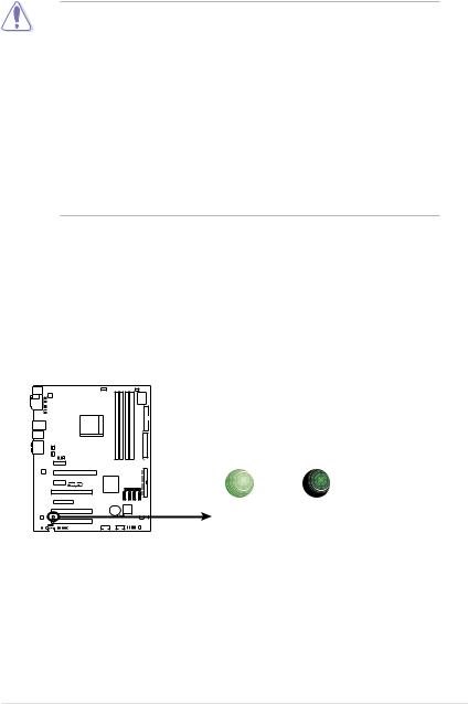
Onboard LED
The motherboard comes with a standby power LED. The green LED lights up to indicate that the system is ON, in sleep mode, or in soft off mode. This is a reminder that you should shut down the system and unplug the power cable before removing or plugging in any motherboard component. The illustration below shows the location of the onboard LED.
SB_PWR |
|
M2N-E |
|
ON |
OFF |
Standby |
Powered |
Power |
Off |
M2N-E Onboard LED |
|
ASUS M2N-E |
2- |
2.2Motherboard overview
Before you install the motherboard, study the configuration of your chassis to ensure that the motherboard fits into it.
Make sure to unplug the power cord before installing or removing the motherboard. Failure to do so can cause you physical injury and damage motherboard components.
2.2.1Placement direction
When installing the motherboard, make sure that you place it into the chassis in the correct orientation. The edge with external ports goes to the rear part of the chassis as indicated in the image below.
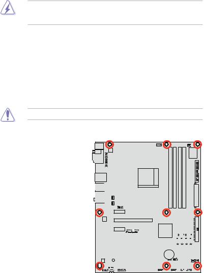
2.2.2Screw holes
Place nine (9) screws into the holes indicated by circles to secure the motherboard to the chassis.
Do not overtighten the screws! Doing so can damage the motherboard.
Place this side towards 
 the rear of the chassis


M2N-E |
|
|
|
|
|
|
|
|
|
|
|
|
|
|
|
|
|
|
|
|
|
|
|
|
|
|
|
|
|
|
|
|
|
|
|
|
|
|
|
|
|
|
|
|
|
|
|
|
|
|
|
|
|
|
|
|
|
|
|
|
|
|
|
|
|
|
|
|
|
|
|
|
|
|
|
|
|
|
|
|
|
|
|
|
|
|
|
|
|
|
|
|
|
|
|
|
|
|
|
|
|
|
|
|
|
|
|
|
|
|
|
|
|
|
|
|
|
|
|
|
|
|
|
|
|
|
|
|
|
|
|
|
|
|
|
|
|
|
|
|
|
|
|
|
|
|
|
|
|
|
|
|
|
|
|
|
|
|
|
|
|
|
|
|
|
|
|
|
|
|
|
|
|
|
|
|
2- |
|
|
|
|
Chapter 2: Hardware information |
||||||||||

2.2.3Motherboard layout
24.5cm (9.6in)
|
|
|
|
|
|
|
PS/2KBMS |
|
|
|
|
|
T: Mouse |
|
|
|
ATX12V |
|
B: Keyboard |
|
|
|
|
|
|
|
|
|
|
|
SPDIF_O1 |
|
|
|
|
|
COM1 |
|
|
|
LPT |
|
|
|
|
|
|
|
|
|
|
|
|
|
|
|
|
|
|
|
|
|
|
|
|
|
|
|
|
|
|
|
|
|
|
|
|
|
|
|
|
|
|
|
|
|
|
|
|
LAN1_USB12
USB34
AUDIO
CHA_FAN1 CHA_FAN2
USB910
|
|
|
|
|
|
|
|
|
|
|
|
|
|
PWR_FAN |
||||||||
|
|
|
|
|
|
|
|
|
|
|
|
|
|
|
|
|
|
|
|
|
|
|
|
|
|
CPU_FAN |
|
|
|
|
|
|
|
|
|
|
|
|
|
|
|
|
|||
|
|
|
|
|
|
|
|
|
|
|
|
|
|
|
|
|
Super I/O |
|
||||
|
|
|
|
|
|
|
DIMM B1 (240-pin module) |
|
DIMM B2 (240-pin module) |
|
DIMM A1 (240-pin module) |
|
DIMM A2 (240-pin module) |
|
|
|
|
|
|
|
|
|
|
|
|
|
|
|
|
|
|
|
|
|
|
|
|
|
|
|
|
||||
|
|
|
|
|
|
|
|
|
|
|
|
|
|
|
|
|
|
|
||||
|
|
|
Socket AM2 |
|
|
|
|
|
|
|
|
|
|
|
||||||||
|
|
|
|
|
|
|
|
|
|
|
|
|
|
|
|
|
||||||
|
|
|
|
|
|
|
|
|
|
|
|
|
|
|
FLOPPY |
|||||||
|
|
|
|
|
|
|
|
|
|
|
|
|
|
|
|
|
||||||
|
|
|
|
|
|
|
|
|
|
|
|
|
|
|
|
|
|
|
||||
|
|
|
|
|
|
|
|
|
|
|
|
|
|
|
|
|||||||
|
|
|
|
|
|
|
DDR2 |
|
DDR2 |
|
DDR2 |
|
DDR2 |
|
|
|
|
|
EATXPWR |
|
|
|
|
|
|
|
|
|
|
|
|
|
|
|
|
|
|
|
|
|
|
|
|
|
|
|
|
|
|
|
|
|
|
|
|
|
|
|
|
|
|
|
|
|
|
|
|
|
|
|
|
|
|
|
|
|
|
|
|
|
|
|
|
|
|
|
|
|
|
|
|
PCIEX1_1
PRI_IDE
Marvell |
PCIEX16_1 |
|
88E1116 |
||
|
||
|
|
M2N-E |
|
nVIDIA |
|
|
|
PCIEX1_2 |
R |
NF570 |
|
|
|
|
|
SATA5 |
|
SATA6 |
|
|
|
Ultra |
|
||
|
|
|
|
|
|
PCI1 |
|
|
|
|
|
|
|
SATA1 |
SATA2 |
SATA3 |
SATA4 |
PCIEX4 |
|
|
|
|
|
|
|
|
CR2032 3V |
4Mb |
|
|
|
|
BIOS |
|
|
|
PCI2 |
|
Lithium Cell |
|
|
|
|
CMOS Power |
|
|
|
|
|
|
|
CLRTC |
CHA_FAN3 |
ADI |
SB_PWR |
|
|
CHASSIS |
|
1988 |
|
|
|
|
|
|
PCI3 |
|
|
|
CHA_FAN4 |
|
|
|
|
|
|
|
SPDIF_OUT |
USB78 |
USB56 |
|
|
|
CD |
|
AAFP |
ADH |
PANEL |
|
30.5cm (12.0in)
ASUS M2N-E |
2- |

2.2.4Layout contents
Slots |
|
Page |
1. |
DDR2 DIMM slots |
2-11 |
2. |
PCI slots |
2-17 |
3. |
PCI Express x1 slots |
2-18 |
4. |
PCI Express x4 slot |
2-18 |
5. |
PCI Express x16 slot |
2-18 |
Jumper |
|
Page |
1. |
Clear RTC RAM (3-pin CLRTC) |
2-19 |
|
|
|
Rear panel connectors |
Page |
|
1. |
PS/2 mouse port (green) |
2-20 |
2. |
Serial (COM) port |
2-20 |
3. |
LAN 1 (RJ-45) port. |
2-20 |
4. |
Rear Speaker Out port (black) |
2-20 |
5. |
Center/Subwoofer port (orange) |
2-20 |
6. |
Line In port (light blue) |
2-20 |
7. |
Line Out port (lime) |
2-20 |
8. |
Microphone port (pink) |
2-20 |
9. |
Side Speaker Out port (gray) |
2-20 |
10. |
USB 2.0 ports 1 and 2, 3 and 4 |
2-21 |
11. |
Coaxial S/PDIF Out port |
2-21 |
12. |
PS/2 keyboard port (purple) |
2-21 |
2- |
Chapter 2: Hardware information |

Internal connectors |
Page |
1. |
Floppy disk drive connector (34-1 pin FLOPPY) |
2-21 |
2. |
IDE connector (40-1 pin PRI_IDE) |
2-22 |
3. |
NVIDIA® nForce 570 Ultra Serial ATA connectors |
2-23 |
|
(7-pin SATA1 [red], SATA2 [red], SATA3 [red], |
|
|
SATA4 [red], SATA5 [red], SATA6 [red]) |
|
4. |
USB connectors (10-1 pin USB56, USB78, USB910) |
2-24 |
5. |
Digital audio connector (4-1 pin SPDIF_OUT) |
2-24 |
6. |
CPU, chassis, and power fan connectors |
2-25 |
|
(4-pin CPU_FAN, 3-pin CHA_FAN1, 3-pin CHA_FAN2, |
|
|
3-pin CHA_FAN3, 3-pin CHA_FAN4, 3-pin PWR_FAN1) |
|
7. |
Chassis intrusion connector (4-1 pin CHASSIS) |
2-26 |
8. |
Optical drive audio connector (4-pin CD) |
2-26 |
9. |
Front panel audio connector (10-1 pin AAFP) |
2-27 |
10. |
ATX power connectors (24-pin EATXPWR, 4-pin EATX12V) |
2-28 |
11. |
Parallel port connector (26-1 pin LPT) |
2-29 |
12. |
System panel connector (20-8 pin PANEL) |
2-30 |
• System power LED (2-pin LED)
• Hard disk drive activity LED (2-pin IDE_LED)
• System warning speaker (4-pin SPEAKER)
• ATX power button/soft-off button (2-pin PWR)
• Reset button (2-pin RESET)
ASUS M2N-E |
2- |
2.3Central Processing Unit (CPU)
The motherboard comes with a 940-pin AM2 socket designed for the AMD Athlon™ 64/AMD Athlon™ 64 FX/AMD Athlon™ 64 X2 and AMD Sempron™ processors.
The AM2 socket has a different pin layout from the 940-pin socket designed for the AMD AM2 processor. Make sure you use a CPU is designed for the AM2 socket. The CPU fits in only one correct orientation. DO NOT force the CPU into the socket to prevent bending the connectors on the socket and damaging the
CPU!
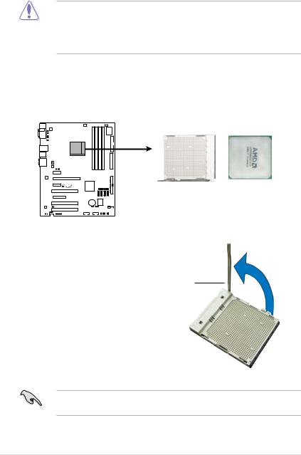
2.3.1Installing the CPU
To install a CPU:
1.Locate the CPU socket on the motherboard.
M2N-E |
M2N-E CPU Socket AM2 |
2.Unlock the socket by pressing the lever sideways, then lift it up to a 90º angle.
Socket lever
Make sure that the socket lever is lifted up to a 90º angle; otherwise, the CPU will not fit in completely.
2- |
Chapter 2: Hardware information |
 Loading...