


AAM6020VI-T4 CPE User Manual
AAM6020VI-T4
UserManual
Rev. 1.02
Version date: January 11, 2005
|
|
AAM6020VI-T4 User Manual |
|
Table of Contents |
|
||
1. |
Introduction |
4 |
|
|
1.1 |
Features & System Requirements |
4 |
2. Your CPE at a glance |
5 |
||
|
2.1 |
Ports and buttons (Back panel) |
5 |
|
2.2 |
LED description (Front panel) |
5 |
|
2.3 |
LED table & parts list |
6 |
3. |
Getting Start |
7 |
|
|
3.1 |
Connecting the Hardware |
7 |
|
3.1.1 |
Connect the ADSL line |
7 |
|
3.1.2 |
Connect the computers or a LAN |
7 |
|
3.1.3 |
Attach the power adapter |
7 |
|
3.1.4 |
Turn on your computer |
7 |
|
3.2 |
Configuring Your PC |
8 |
|
3.2.1 |
Windows XP |
8 |
|
3.2.2 |
Windows 2000 |
8 |
|
3.2.3 |
Windows Me |
9 |
|
3.2.4 |
Windows 95/98 |
10 |
|
3.2.5 |
Windows NT 4.0 |
11 |
|
3.2.6 |
Assigning IP to your PC automatically by DHCP |
11 |
4. Setting up your CPE |
12 |
||
|
4.1 |
Log into your CPE |
12 |
|
4.2 |
Home screen |
12 |
|
4.3 |
Setup |
13 |
|
4.3.1 |
Wide Area Network connection |
13 |
|
4.3.2 |
Local Area Network connection |
14 |
|
4.4 |
Configuring the WAN |
14 |
|
4.4.1 |
New Connection |
14 |
|
4.4.2 |
Modify an Existing Connection |
19 |
|
4.4.3 |
Modem setup |
19 |
|
4.5 |
Configuring the LAN |
19 |
|
4.5.1 |
Enable/Disable DHCP |
19 |
|
4.5.2 |
Changing the CPEs IP address |
21 |
|
4.5.3 |
Firewall/NAT Services |
22 |
|
4.6 |
Advanced |
22 |
|
4.6.1 |
UPnP |
23 |
|
4.6.2 |
Port Forwarding |
24 |
|
4.6.3 |
IP QoS/IP filters |
25 |
|
4.6.4 |
Access Control |
26 |
|
4.6.5 |
LAN clients |
26 |
|
4.6.6 |
Bridge Filters |
26 |
|
4.6.7 |
Multicast |
27 |
|
4.6.8 |
Static Routing |
28 |
|
4.6.9 |
Dynamic Routing |
29 |
|
4.7 |
Wireless |
31 |
|
4.7.1 |
Setup |
31 |
2 |
2 |
|
|
AAM6020VI-T4 User Manual |
|
|
4.7.2 |
Configuration |
32 |
|
4.7.3 |
Security |
32 |
|
4.7.4 |
Management |
33 |
|
4.8 |
Tools |
34 |
|
4.8.1 |
System Commands |
34 |
|
4.8.2 |
Remote Log |
34 |
|
4.8.3 |
User Management |
34 |
|
4.8.4 |
Update Gateway |
35 |
|
4.8.5 |
Ping Test |
35 |
|
4.8.6 |
Modem Test |
36 |
|
4.9 |
Status |
36 |
|
4.9.1 |
Network Statistics |
36 |
|
4.9.2 |
Connection Status |
36 |
|
4.9.3 |
DHCP Clients |
36 |
|
4.9.4 |
Modem Status |
36 |
|
4.9.5 |
Product Information |
36 |
|
4.9.6 |
System Log |
37 |
5. |
Appendix A: Troubleshooting |
38 |
|
|
5.1 |
The CPE is not functional |
38 |
|
5.2 |
I can’t connect to the CPE. |
38 |
|
5.3 |
The LEDs blink in a sequential pattern. |
38 |
|
5.4 |
The DSL Link LED continues to blink but does not go solid |
39 |
|
5.5 |
The DSL Link LED is always off |
39 |
6. |
Router terms |
40 |
|
3 |
3 |
AAM6020VI-T4 User Manual
1.Introduction
Congratulations on becoming the owner of an ASUS AAM6020VI-T4 CPE (Customer Premises Equipment). Your LAN (Local Area Network) will now be able to access the Internet via the CPE’s ADSL connection.
This User Manual will show you how to set up the AAM6020VI-T4 CPE, and how to customize its configuration to get the most out of this product.
1.1Features & System Requirements
Features
•Equipped with a 4 Port 10/100 Ethernet
•Connects multiple PCs to the Internet with just one WAN IP Address (when configured in router mode with NAT enabled)
•Configurable through user-friendly web pages
•Supports Single-Session IPSec and PPTP Pass-Through for Virtual Private Network (VPN)
•Several popular games are already pre configured. Just enable the game and the port settings are automatically configured.
•Configurable as a DHCP Server on Your Network
•Compatible with virtually all standard Internet applications
•Industry standard and interoperable DSL interface
•Simple web based status page displays a snapshot of your system configuration, and links to the configuration pages
•Downloadable flash software upgrades
•Support for up to 8 Permanent Virtual Circuits (PVC)
•Support for up to 8 PPPOE sessions
•Layer 2 Ethernet switch (not a hub)
•PVC assignment must be operational in bridged mode (RFC 1483/2684)
System Requirements
In order to use the AAM6020VI-T4 CPE for Internet access, you must have the following:
ADSL service subscription from your ISP.
One computer containing an Ethernet 10BaseT/100BaseT network interface card (NIC).
(Optional) An Ethernet hub/switch, if you are connecting the device to several computers on an Ethernet network.
For system monitoring or configuration using the supplied web-based program: a web browser such as Internet Explorer Version 5.5 or later.
4 |
4 |
AAM6020VI-T4 User Manual
2.Your CPE at a glance
Your CPE has many ports, switches and LEDs. Let’s take a look at the different options. Depending upon your model of CPE, your CPE may have some or all of the features listed below
2.1Ports and buttons (Back panel)
Power is where you connect the power.
LAN 1~4 (local area network) port: connect to Ethernet network devices, such as a PC, hub, switch, or router. Some CPEs come with a single LAN connection and some come with four LAN connections. Depending on the connection, you may need a cross over cable or a strait through cable.
Reset Button: The reset button is used to reset the CPE to default setting. You may need to reset the CPE if you loose network connectivity or you loose the ability to interface to the CPE via the web interface. To reset the CPE, simply press the reset button for about 5-10 seconds and release. After about 30 seconds the CPE will become operational.
DSL (Line) port: This is the WAN interface that connects directly to your phone line.
2.2LED description (Front panel)
Power LED: On indicates that the power is supplied to the CPE
Status LED: The Status LED serves two purposes. If the LED is continuously lit, the DSL interface is successfully connected to a device through the WAN port. If the LED is flickering, it is an indication that the modem is training.
Activity LED: The Activity LED flash during ADSL data transfer.
LAN 1~4 LED: The LAN’s LED serves two purposes. If the LED is continuously lit, the Ethernet interface is successfully connected to a device through the LAN port. If the LED is flickering, it is an indication of any network activity.
WLAN LED: The Wireless LAN’s LED. This LED is continuously lit due to power up and flickering if any Wireless network activity in device.
5 |
5 |
AAM6020VI-T4 User Manual
2.3LED table & parts list
LED Table
The LEDs can help diagnose problems. If you are using an AAM6020VI-T4 CPE, you will have the LEDs shown in Table 1
Label |
Color |
Function |
POWER |
Green |
On: Unit is powered on |
|
|
Off: Unit is powered off |
STATUS |
Blue |
Flashing: ADSL data transfer |
|
|
|
LINE |
Blue |
On: ADSL link is established and active |
|
|
Flashing: Trying to create an ADSL connection |
|
|
Off: No ADSL link |
|
|
|
TEST |
Blue |
Device in test mode |
LAN 1~4 |
Blue |
On: LAN link is established |
|
|
Flashing: Data transfer at LAN connection |
|
|
Off: No LAN link |
|
|
|
WLAN |
Blue |
On: WLAN is service |
|
|
Off: No WLAN in service of device |
|
|
Table 1 (Front Panel & LEDs) |
Parts List
In addition to this document, your AAM6020VI-T4 should come with the following:
AAM6020VI-T4 4 Port ADSL WLAN Router Power adapter
Ethernet cable (RJ45), Phone cable (RJ-11) User Manual & Quick Guide
6 |
6 |
AAM6020VI-T4 User Manual
3.Getting Start
This chapter provides basic instructions for connecting the CPE to a computer or a LAN and to the Internet via ADSL.
Part 1 provides instructions to set up the hardware.
Part 2 describes how to configure Internet properties on your computer(s). Part 3 shows you how to access your CPE.
It is assumed that you have already subscribed to ADSL service with your telephone company or other Internet service provider (ISP). These instructions provide a basic configuration that should be compatible with your home or small office network setup. Refer to the subsequent chapters for additional configuration instructions.
3.1Connecting the Hardware
In 3.1, you should connect the device to an ADSL line, the power outlet, and your computer or network.
3.1.1Connect the ADSL line
Connect your ADSL line to the port labeled LINE on the rear panel of the device, and connect the other end of the line to the wall phone jack directly or to an optional POTS splitter. If you use a POTS splitter to connect a telephone to the same wall jack as the CPE, follow the instructions that came with the splitter.
3.1.2Connect the computers or a LAN
You can use the included Ethernet cable to connect your computer directly to the CPE. Attach one end of the Ethernet cable to the port labeled LAN on the rear panel of the device and connect the other end to the Ethernet port of your computer.
If your LAN has more than one computer, you can attach one end of an Ethernet cable to a hub or a switch and the other to the port labeled LAN on the CPE.
Note that either a crossover or a straight-through Ethernet cable can be used. The CPE determines and adjusts to the type of signal required.
3.1.3Attach the power adapter
Connect the cylindrical power plug into the POWER connector on the back of the device.
3.1.4Turn on your computer
Turn on and boot up your computer and any other LAN devices, such as hubs or switches.
7 |
7 |

AAM6020VI-T4 User Manual
3.2Configuring Your PC
Before you start to access the CPE via Ethernet, you must configure your PC’s TCP/IP address to be 192.168.1.x, where x is any number between 2 and 254. The subnet mask must be 255.255.255.0. Your CPE’s default IP address is 192.168.1.1.
If you use Ethernet cable to connect your AAM6020VI-T4 and PC, you don’t need any specific driver installation.
3.2.1Windows XP:
1.In the Windows task bar, click on the Start button, and then click on Control Panel.
2.Double-click on the Network Connections icon.
3.In the LAN or High-Speed Internet window, right-click on the icon corresponding to your network interface card (NIC) and select Properties. (Often this icon is labeled Local Area Connection). The Local Area Connection dialog box is displayed with a list of currently installed network items.
4.Ensure that the check box to the left of the item labeled Internet Protocol (TCP/IP) is checked,
and click on  .
.
.
Figure 3.7 Network
Connections in
Windows XP
Figure 3.8 Local Area Connection Properties in Windows XP
5.In the Internet Protocol (TCP/IP) Properties dialog box, click in the radio button labeled Use the following IP address and type 192.168.1.x (where x is any number between 2 and 254) and 255.255.255.0 in the IP address field and Subnet Mask field, respectively.
3.2.2Windows 2000:
1.In the Windows task bar, click on the Start button, point to Settings, and then select Control Panel.
2.Double-click on the Network and Dial-up Connections icon.
3.In the Network and Dial-up Connections window, right-click on the Local Area Connection icon, and then select Properties.
8 |
8 |

AAM6020VI-T4 User Manual
The Local Area Connection Properties dialog box is displayed with a list of currently installed network components. If the list includes Internet Protocol (TCP/IP), the protocol has already been enabled, in which case you can skip to Step 10.
4.If Internet Protocol (TCP/IP) does not appear as an installed component, click on  .
.
5.In the Select Network Component Type dialog box, select Protocol, and then click on  .
.
6.Select Internet Protocol (TCP/IP) in the Network Protocols list, and then click on  .
.
You may be prompted to install files from your Windows 2000 installation CD or other media. Follow the instructions to install the files.
7.If prompted, click on  to restart your computer with the new settings.
8.After restarting your PC, double-click on the Network and Dial-up Connections icon in the
Control Panel.
9.In Network and Dial-up Connections window, right-click on the Local Area Connection icon, and then select Properties.
10.In the Local Area Connection Properties dialog box, select Internet Protocol (TCP/IP), and then click on  .
.
11.In the Internet Protocol (TCP/IP) Properties dialog box, click in the radio button labeled Use the following IP address and type 192.168.1.x (where x is any number between 2 and 254) and 255.255.255.0 in the IP address field and Subnet Mask field, respectively.
12.Click on  twice to confirm and save your changes, and then close the Control Panel.
3.2.3Windows Me:
1.In the Windows task bar, click on the Start button, point to Settings, and then click Control Panel.
2.Double-click on the Network and Dial-up Connections icon.
3.In the Network and Dial-up Connections window, right-click on the Network icon, and then select Properties.
The Network Properties dialog box is displayed with a list of currently installed network components. If the list includes Internet Protocol (TCP/IP), the protocol has already been enabled, in which case you can skip to Step 11.
4.If Internet Protocol (TCP/IP) does not appear as an installed component, click on  .
.
5.In the Select Network Component Type dialog box, select Protocol, and then click  .
.
6.Select Microsoft in the Manufacturers box.
7.Select Internet Protocol (TCP/IP) in the Network Protocols list, and then click on  .
.
You may be prompted to install files from your Windows Me installation CD or other media. Follow the instructions to install the files.
9 |
9 |

AAM6020VI-T4 User Manual
8.If prompted, click on  to restart your computer with the new settings.
9.After restarting your PC, double-click on the Network and Dial-up Connections icon in the
Control Panel.
10.In Network and Dial-up Connections window, right-click on the Network icon, and then select
Properties.
11.In the Network Properties dialog box, select TCP/IP, and then click on  .
.
12.In the TCP/IP Settings dialog box, click in the radio button labeled Use the following IP address and type 192.168.1.x (where x is any number between 2 and 254) and 255.255.255.0 in the IP address field and Subnet Mask field, respectively.
13.Click on  twice to confirm and save your changes, and then close the Control Panel.
3.2.4Windows 95, 98:
1.In the Windows task bar, click on the Start button, point to Settings, and then click Control Panel.
2.Double-click on the Network icon.
The Network dialog box is displayed with a list of currently installed network components. If the list includes TCP/IP, the protocol has already been enabled, in which case you can skip to Step 9.
3.If TCP/IP does not appear as an installed component, click on  . The Select Network Component Type dialog box appears.
4.Select Protocol, and then click  . The Select Network Protocol dialog box appears.
5.Click on Microsoft in the Manufacturers list box, and then click TCP/IP in the Network Protocols list box.
6.Click  to return to the Network dialog box, and then click
  again.
You may be prompted to install files from your Windows 95/98 installation CD. Follow the instructions to install the files.
7.Click on  to restart the PC and complete the TCP/IP installation.
8.After restarting your PC, open the Control Panel window, and then click on the Network icon.
9.Select the network component labeled TCP/IP, and then click on  .
.
If you have multiple TCP/IP listings, select the listing associated with your network card or adapter.
10.In the TCP/IP Properties dialog box, click on the IP Address tab.
11.Click in the radio button labeled Use the following IP address and type 192.168.1.x (where x is any number between 2 and 254) and 255.255.255.0 in the IP address field and Subnet Mask field, respectively.
12.Click on  twice to confirm and save your changes. You will be prompted to restart Windows. Please click on
  and restart your PC again.
10 |
10 |
AAM6020VI-T4 User Manual
3.2.5Windows NT 4.0:
1.In the Windows NT task bar, click on the Start button, point to Settings, and then click Control Panel.
2.In the Control Panel window, double click on the Network icon.
3.In the Network dialog box, click on the Protocols tab.
The Protocols tab displays a list of currently installed network protocols. If the list includes TCP/IP, the protocol has already been enabled, in which case you can skip to Step 9.
4.If TCP/IP does not appear as an installed component, click on  .
.
5.In the Select Network Protocol dialog box, select TCP/IP, and then click on  .
.
You may be prompted to install files from your Windows NT installation CD or other media. Follow the instructions to install the files.
After all files are installed, a window displays to inform you that a TCP/IP service called DHCP can be set up to dynamically assign IP information.
6.Click on  to continue, and then click on
  if prompted to restart your computer.
7.After restarting your PC, open the Control Panel window, and then double-click on the Network icon.
8.In the Network dialog box, click on the Protocols tab.
9.In the Protocols tab, select TCP/IP, and then click on  .
.
10.In the Microsoft TCP/IP Properties dialog box, click in the radio button labeled Use the following IP address and type 192.168.1.x (where x is any number between 2 and 254) and 255.255.255.0 in the IP address field and Subnet Mask field, respectively.
11.Click on  twice to confirm and save your changes, and then close the Control Panel.
3.2.6Assigning IP to your PC automatically by DHCP
To use the CPE’s DHCP feature, click in the radio button labeled Obtain an IP address automatically instead of Use the following IP address in the above procedures.
By default, the LAN port IP address of the CPE is 192.168.1.1. (You can change this address, or another address can be assigned by your ISP.)
Now that the hardware installation is complete, proceed to Chapter 4: Setting up your CPE
11 |
11 |
AAM6020VI-T4 User Manual
4.Setting up your CPE
This section will guide you through your CPE’s configuration. The CPE is shipped with a standard default bridge configuration; for most users, you may want to change the CPE from a bridge to a router.
4.1Log into your CPE
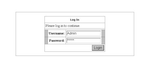
To configure your CPE, open your web browser. You may get an error message at this point; this is normal. Don’t panic. Continue following these directions. Type the default IP address (192.168.1.1) Press the Enter key and the following screen, shown in Figure 1 will appear. The default user name is Admin (case sensitive) and the password is Admin (case sensitive).
Note: Before setting up your CPE, make sure you have followed the quick start guide. You should have your computers configured for DHCP mode and have proxies disabled on your browser. Also if you access the router, and instead of getting a login screen, the browser instead displays a login redirection screen, you should check your browser's setting, and verify that JavaScript support is enabled. Also, if you do not get the screen shown in Figure 1, you may need to delete your temporary Internet files (basically flush the cached web pages).
Figure 1 (Log-in Screen)
4.2Home screen
The first screen (Figure 2) that appears (after the log in screen) is the Home screen. From this screen the user can setup the modem (configure the LAN and WAN connection(s), configure the advanced configuration options within the modem (security, routing, and filtering), access tools that are helpful for debug purposes, obtain the status of the modem, and view the extensive online help.
The basic layout of the Home page consists of a page selection list across the top of the browser window. The footer displays CPE status, connection information, and other useful information. The center display is where most of the configuration will take place.
12 |
12 |
 Loading...