


AT4NM10-I

Motherboard
AT4NM10-I

ii
E5417
First Edition V1
March 2010
Copyright © 2010 ASUSTeK Computer Inc. All Rights Reserved.
No part of this manual, including the products and software described in it, may be reproduced,
transmitted, transcribed, stored in a retrieval system, or translated into any language in any form or by any
means, except documentation kept by the purchaser for backup purposes, without the express written
permission of ASUSTeK Computer Inc. (“ASUS”).
Product warranty or service will not be extended if: (1) the product is repaired, modied or altered, unless
such repair, modication of alteration is authorized in writing by ASUS; or (2) the serial number of the
product is defaced or missing.
ASUS PROVIDES THIS MANUAL “AS IS” WITHOUT WARRANTY OF ANY KIND, EITHER EXPRESS
OR IMPLIED, INCLUDING BUT NOT LIMITED TO THE IMPLIED WARRANTIES OR CONDITIONS OF
MERCHANTABILITY OR FITNESS FOR A PARTICULAR PURPOSE. IN NO EVENT SHALL ASUS, ITS
DIRECTORS, OFFICERS, EMPLOYEES OR AGENTS BE LIABLE FOR ANY INDIRECT, SPECIAL,
INCIDENTAL, OR CONSEQUENTIAL DAMAGES (INCLUDING DAMAGES FOR LOSS OF PROFITS,
LOSS OF BUSINESS, LOSS OF USE OR DATA, INTERRUPTION OF BUSINESS AND THE LIKE),
EVEN IF ASUS HAS BEEN ADVISED OF THE POSSIBILITY OF SUCH DAMAGES ARISING FROM ANY
DEFECT OR ERROR IN THIS MANUAL OR PRODUCT.
SPECIFICATIONS AND INFORMATION CONTAINED IN THIS MANUAL ARE FURNISHED FOR
INFORMATIONAL USE ONLY, AND ARE SUBJECT TO CHANGE AT ANY TIME WITHOUT NOTICE,
AND SHOULD NOT BE CONSTRUED AS A COMMITMENT BY ASUS. ASUS ASSUMES NO
RESPONSIBILITY OR LIABILITY FOR ANY ERRORS OR INACCURACIES THAT MAY APPEAR IN THIS
MANUAL, INCLUDING THE PRODUCTS AND SOFTWARE DESCRIBED IN IT.
Products and corporate names appearing in this manual may or may not be registered trademarks or
copyrights of their respective companies, and are used only for identication or explanation and to the
owners’ benet, without intent to infringe.
Offer to Provide Source Code of Certain Software
This product may contain copyrighted software that is licensed under the General Public License (“GPL”)
and under the Lesser General Public License Version (“LGPL”). The GPL and LGPL licensed code in this
product is distributed without any warranty. Copies of these licenses are included in this product.
You may obtain the complete corresponding source code (as dened in the GPL) for the GPL Software,
and/or the complete corresponding source code of the LGPL Software (with the complete machine-
readable “work that uses the Library”) for a period of three years after our last shipment of the product
including the GPL Software and/or LGPL Software, which will be no earlier than December 1, 2011, either
(1) for free by downloading it from http://support.asus.com/download;
or
(2) for the cost of reproduction and shipment, which is dependent on the preferred carrier and the location
where you want to have it shipped to, by sending a request to:
ASUSTeK Computer Inc.
Legal Compliance Dept.
15 Li Te Rd.,
Beitou, Taipei 112
Taiwan
In your request please provide the name, model number and version, as stated in the About Box of the
product for which you wish to obtain the corresponding source code and your contact details so that we
can coordinate the terms and cost of shipment with you.
The source code will be distributed WITHOUT ANY WARRANTY and licensed under the same license as
the corresponding binary/object code.
This offer is valid to anyone in receipt of this information.
ASUSTeK is eager to duly provide complete source code as required under various Free Open Source
Software licenses. If however you encounter any problems in obtaining the full corresponding source code
we would be much obliged if you give us a notication to the email address gpl@asus.com, stating the
product and describing the problem (please do NOT send large attachments such as source code archives
etc to this email address).

iii
Contents
Notices .......................................................................................................... v
Safety information ...................................................................................... vi
About this guide ......................................................................................... vi
AT4NM10-I specications summary ....................................................... viii
Chapter 1: Product introduction
1.1 Before you proceed ..................................................................... 1-1
1.2 Motherboard overview .................................................................
1-2
1.2.1 Motherboard layout .........................................................
1-2
1.2.2 Layout contents ...............................................................
1-2
1.3 Central Processing Unit (CPU) ...................................................
1-3
1.4 System memory ...........................................................................
1-3
1.4.1 Overview .........................................................................
1-3
1.4.2 Memory congurations ....................................................
1-4
1.5 Expansion slot ..............................................................................
1-8
1.5.1 Installing an expansion card ...........................................
1-8
1.5.2 Conguring an expansion card .......................................
1-8
1.5.3 PCI slot ...........................................................................
1-8
1.6 Jumpers ........................................................................................
1-9
1.7 Connectors .................................................................................
1-11
1.7.1 Rear panel connectors ...................................................
1-11
1.7.2 Internal connectors .......................................................
1-12
1.8 Software support ........................................................................
1-18
1.8.1 Installing an operating system ......................................
1-18
1.8.2 Support DVD information ..............................................
1-18
Chapter 2: BIOS information
2.1 Managing and updating your BIOS ............................................ 2-1
2.1.1 ASUS Update utility ........................................................
2-1
2.1.2 ASUS EZ Flash 2 ............................................................
2-2
2.1.3 ASUS CrashFree BIOS ...................................................
2-3
2.2 BIOS setup program ....................................................................
2-4

iv
Contents
2.3 Main menu .................................................................................... 2-4
2.3.1 System Time ...................................................................
2-5
2.3.2 System Date ...................................................................
2-5
2.3.3 SATA 1/2 .........................................................................
2-5
2.3.4 Storage Conguration .....................................................
2-6
2.3.5 System Information .........................................................
2-6
2.4 Advanced menu ...........................................................................
2-6
2.4.1 CPU Conguration ..........................................................
2-7
2.4.2 Chipset ............................................................................
2-7
2.4.3 Onboard Devices Conguration ......................................
2-8
2.4.4 USB Conguration ..........................................................
2-9
2.4.5 PCI PnP ........................................................................
2-10
2.5 Power menu ................................................................................
2-10
2.5.1 Suspend Mode ..............................................................
2-10
2.5.2 ACPI 2.0 Support ..........................................................
2-10
2.5.3 ACPI APIC Support .......................................................
2-10
2.5.4 Control EuP ....................................................................
2-11
2.5.5 APM Conguration .........................................................
2-11
2.5.6 Hardware Monitor ..........................................................
2-11
2.6 Boot menu ..................................................................................
2-12
2.6.1 Boot Device Priority ......................................................
2-12
2.6.2 Boot Settings Conguration ..........................................
2-12
2.6.3 Security .........................................................................
2-13
2.7 Tools menu .................................................................................
2-14
2.7.1 ASUS EZ Flash 2 ..........................................................
2-14
2.7.2 Express Gate ................................................................
2-14
2.7.3 AI NET 2
........................................................................ 2-15
2.8 Exit menu ....................................................................................
2-15
v
Notices
Federal Communications Commission Statement
This device complies with Part 15 of the FCC Rules. Operation is subject to the following two
conditions:
•
This device may not cause harmful interference, and
•
This device must accept any interference received including interference that may cause
undesired operation.
This equipment has been tested and found to comply with the limits for a Class B digital
device, pursuant to Part 15 of the FCC Rules. These limits are designed to provide
reasonable protection against harmful interference in a residential installation. This
equipment generates, uses and can radiate radio frequency energy and, if not installed
and used in accordance with manufacturer’s instructions, may cause harmful interference
to radio communications. However, there is no guarantee that interference will not occur
in a particular installation. If this equipment does cause harmful interference to radio or
television reception, which can be determined by turning the equipment off and on, the user
is encouraged to try to correct the interference by one or more of the following measures:
•
Reorient or relocate the receiving antenna.
•
Increase the separation between the equipment and receiver.
•
Connect the equipment to an outlet on a circuit different from that to which the receiver is
connected.
•
Consult the dealer or an experienced radio/TV technician for help.
Canadian Department of Communications Statement
This digital apparatus does not exceed the Class B limits for radio noise emissions from
digital apparatus set out in the Radio Interference Regulations of the Canadian Department
of Communications.
This class B digital apparatus complies with Canadian ICES-003.
REACH
Complying with the REACH (Registration, Evaluation, Authorisation, and Restriction of
Chemicals) regulatory framework, we published the chemical substances in our products at
ASUS REACH website at http://green.asus.com/english/REACH.htm.
The use of shielded cables for connection of the monitor to the graphics card is required
to assure compliance with FCC regulations. Changes or modications to this unit not
expressly approved by the party responsible for compliance could void the user’s authority
to operate this equipment.
DO NOT throw the motherboard in municipal waste. This product has been designed to
enable proper reuse of parts and recycling. This symbol of the crossed out wheeled bin
indicates that the product (electrical and electronic equipment) should not be placed in
municipal waste. Check local regulations for disposal of electronic products.
DO NOT throw the mercury-containing button cell battery in municipal waste. This symbol
of the crossed out wheeled bin indicates that the battery should not be placed in municipal
waste.

vi
Safety information
Electrical safety
•
To prevent electric shock hazard, disconnect the power cable from the electric outlet
before relocating the system.
•
When adding or removing devices to or from the system, ensure that the power cables
for the devices are unplugged before the signal cables are connected. If possible,
disconnect all power cables from the existing system before you add a device.
•
Before connecting or removing signal cables from the motherboard, ensure that all
power cables are unplugged.
•
Seek professional assistance before using an adapter or extension cord. These devices
could interrupt the grounding circuit.
•
Ensure that your power supply is set to the correct voltage in your area. If you are not
sure about the voltage of the electrical outlet you are using, contact your local power
company.
•
If the power supply is broken, do not try to x it by yourself. Contact a qualied service
technician or your retailer.
Operation safety
•
Before installing the motherboard and adding devices on it, carefully read all the manuals
that came with the package.
•
Before using the product, ensure that all cables are correctly connected and the power
cables are not damaged. If you detect any damage, contact your dealer immediately.
•
To avoid short circuits, keep paper clips, screws, and staples away from connectors,
slots, sockets and circuitry.
•
Avoid dust, humidity, and temperature extremes. Do not place the product in any area
where it may become wet.
•
Place the product on a stable surface.
•
If you encounter technical problems with the product, contact a qualied service
technician or your retailer.
About this guide
This user guide contains the information you need when installing and conguring the
motherboard.
How this guide is organized
This guide contains the following parts:
•
Chapter 1: Product introduction
This chapter describes the features of the motherboard and the new technology it
supports.
• Chapter 2: BIOS information
This chapter tells how to change system settings through the BIOS Setup menus.
Detailed descriptions of the BIOS parameters are also provided.

vii
Conventions used in this guide
To ensure that you perform certain tasks properly, take note of the following symbols used
throughout this manual.
DANGER/WARNING: Information to prevent injury to yourself when trying to
complete a task.
CAUTION: Information to prevent damage to the components when trying to
complete a task.
NOTE: Tips and additional information to help you complete a task.
IMPORTANT: Instructions that you MUST follow to complete a task.
Where to nd more information
Refer to the following sources for additional information and for product and software
updates.
1. ASUS websites
The ASUS website provides updated information on ASUS hardware and software
products. Refer to the ASUS contact information.
2. Optional documentation
Your product package may include optional documentation, such as warranty yers,
that may have been added by your dealer. These documents are not part of the
standard package.
Typography
Bold text Indicates a menu or an item to select.
Italics
Used to emphasize a word or a phrase.
<Key> Keys enclosed in the less-than and greater-than sign means
that you must press the enclosed key.
Example: <Enter> means that you must press the Enter or
Return key.
<Key1>+<Key2>+<Key3> If you must press two or more keys simultaneously, the key
names are linked with a plus sign (+).
Example: <Ctrl>+<Alt>+<D>

viii
CPU Integrated Intel
®
Atom™ D410 processor
Chipset Intel
®
NM10
Memory Single channel memory architecture
- 2 x 240-pin DIMM sockets support maximum 4GB
unbuffered non-ECC DDR2 800/667 MHz memory
modules
* Refer to www.asus.com or this user manual for the
Memory QVL (Qualied Vendors Lists).
** When you install a total memory of 4GB capacity
or more, Windows
®
32-bit operating system may only
recognize less than 3GB. We recommend a maximum
of 3GB system memory if you are using a Windows
®
32-bit operating system.
Graphics Integrated Intel
®
graphics Atom™ D410
Maximum shared memory of 256MB
Expansion slot 1 x PCI slot
Storage 2 x Serial ATA 3Gb/s ports support AHCI mode
Audio IDT 92HD73C 6-channel High Denition Audio CODEC
LAN Realtek
®
RTL8112L PCIe Gigabit LAN controller
USB Supports up to 8 USB 2.0/1.1 ports (4 ports at mid-board,
4 ports at back panel)
ASUS special features ASUS CrashFree BIOS 3
ASUS EZ Flash 2
ASUS MyLogo 2™
ASUS AI NET 2
ASUS Express Gate
Rear panel ports 1 x PS/2 Keyboard port
1 x PS/2 Mouse port
1 x COM port
1 x VGA port
1 x LPT port
1 x LAN (RJ-45) port
4 x USB 2.0/1.1 ports
6-channel audio I/O ports
AT4NM10-I specications summary
(continued on the next page)

ix
AT4NM10-I specications summary
Internal connectors 2 x USB 2.0/1.1 connector supports additional 4 USB 2.0/1.1
ports
1 x CPU fan connector
1 x Chassis fan connector
1 x Chassis intrusion connector
1 x S/PDIF Out connector
1 x Speaker connector
1 x COM connector
1 x LVDS connector
2 x Serial ATA connectors
1 x System panel connector
1 x Front panel audio connector
1 x 24-pin EATX power connector
1 x 4-pin ATX 12V power connector
BIOS features 8 Mb Flash ROM, AMI BIOS, PnP, DMI2.0, WfM2.0,
SMBIOS 2.5
Accessories 1 x Serial ATA cable
1 x I/O shield
1 x User Manual
Support DVD contents Drivers
ASUS PC Probe II
ASUS Update
Anti-virus software (OEM version)
Form Factor Mini ITX form factor: 6.75 in x 6.75 in (17.1cm x 17.1cm)
* Specications are subject to change without notice.
1-1 Chapter 1: Product introduction
Chapter 1
Product introduction
If any of the items is damaged or missing, contact your retailer.
Thank you for buying an ASUS
®
AT4NM10-I motherboard!
Before you start installing the motherboard, and hardware devices on it, check the items in
your motherboard package. Refer to page ix for the list of accessories.
1.1 Before you proceed
Take note of the following precautions before you install motherboard components or change
any motherboard settings.
• Unplug the power cord from the wall socket before touching any component.
• Before handling components, use a grounded wrist strap or touch a safely grounded
object or a metal object, such as the power supply case, to avoid damaging them due to
static electricity.
• Hold components by the edges to avoid touching the ICs on them.
• Whenever you uninstall any component, place it on a grounded antistatic pad or in the
bag that came with the component.
• Before you install or remove any component, ensure that the ATX power supply is
switched off or the power cord is detached from the power supply. Failure to do so may
cause severe damage to the motherboard, peripherals, or components.
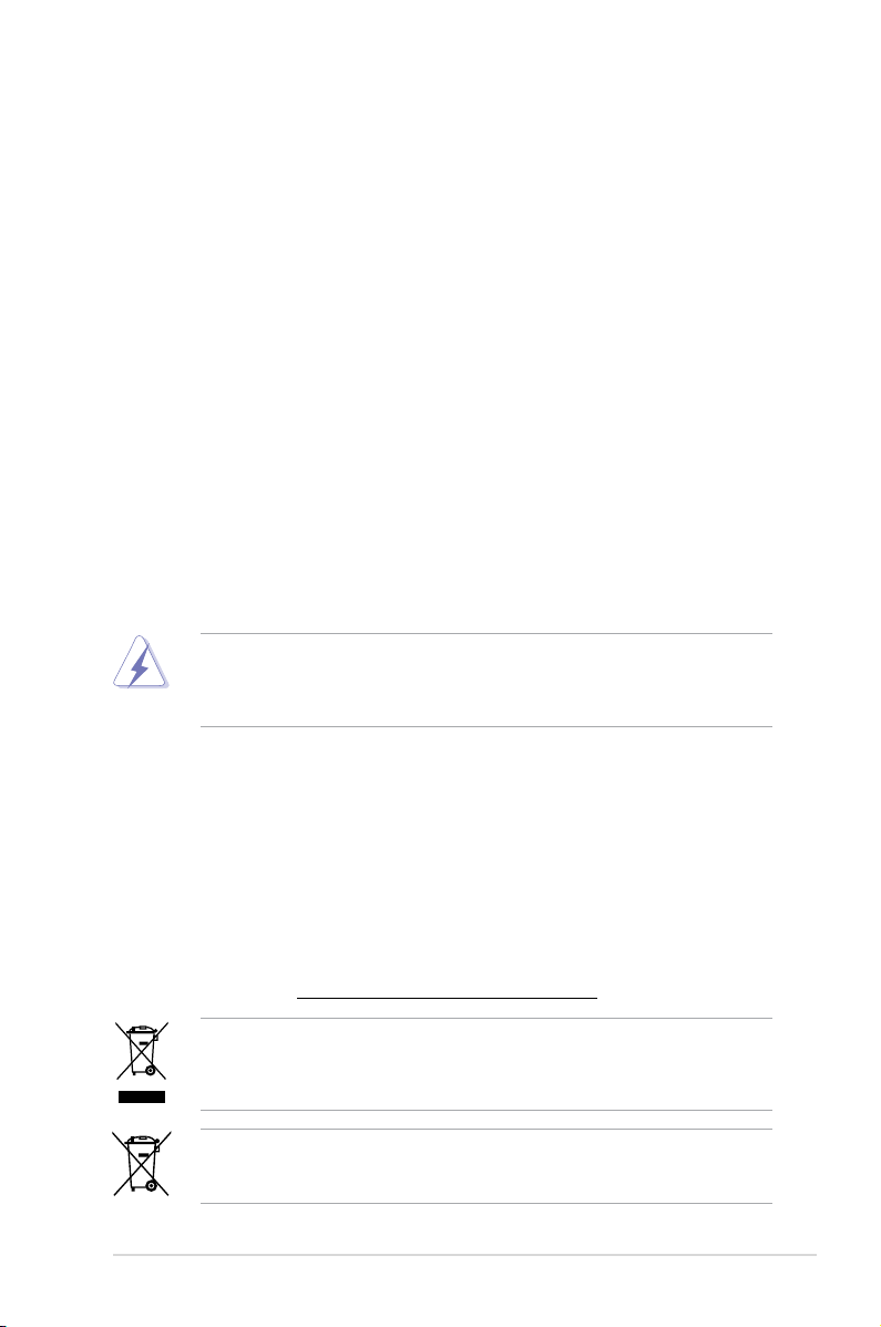
Onboard LED
The motherboard comes with a standby power LED that lights up to indicate that the system
is ON, in sleep mode, or in soft-off mode. This is a reminder that you must shut down
the system and unplug the power cable before removing or plugging in any motherboard
component. The illustration below shows the location of the onboard LED.
AT4NM10-I Onboard LED
AT4NM10-I
ASUS AT4NM10-I 1-2
1.2.2 Layout contents
1.2 Motherboard overview
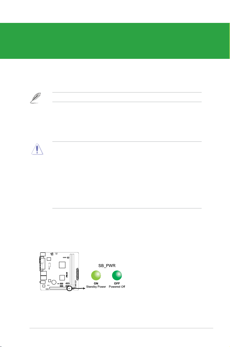
1.2.1 Motherboard layout
Place four screws into the holes indicated by circles to secure the motherboard to the
chassis. DO NOT overtighten the screws! Doing so can damage the motherboard.
Ensure that you install the motherboard into the chassis in the correct orientation. The edge
with external ports goes to the rear part of the chassis.
Place this side towards
the rear of the chassis.
Atom D410
AT4NM10-I
Connectors/Jumpers/Slots/LED Page Connectors/Jumpers/Slots/LED Page
1.
Keyboard/mouse power and USB device
wake-up (3-pin PS2_USBPW1-4, 3-pin USBPW5-
8)
1-10 9.
Chassis intrusion connector (4-1 pin
CHASSIS)
1-14
2. Serial port connector (10-1 pin COM2) 1-17 10.
Internal speaker connector (4-pin
SPEAKER)
1-14
3.
ATX power connectors (24-pin EATXPWR, 4-pin
ATX12V)
1-12 11. Clear RTC RAM (3-pin CLRTC) 1-9
4.
CPU and chassis fan connectors (3-pin
CPU_FAN, 3-pin CHA_FAN)
1-15 12. Onboard LED 1-1
5. LVDS connector (30-pin CON1) 1-16 13. Serial ATA connectors (7-pin SATA1, SATA2) 1-13
6. Intel
®
Atom™ D410 processor 1-15 14. USB connectors (10-1 pin USB56, USB78) 1-13
7. DDR2 DIMM sockets 1-3 15. Digital audio connector (4-1 pin SPDIF_OUT) 1-17
8. System panel connector (10-1 pin F_PANEL) 1-16 16. Front panel audio connector (10-1 pin AAFP) 1-15
1-3 Chapter 1: Product introduction
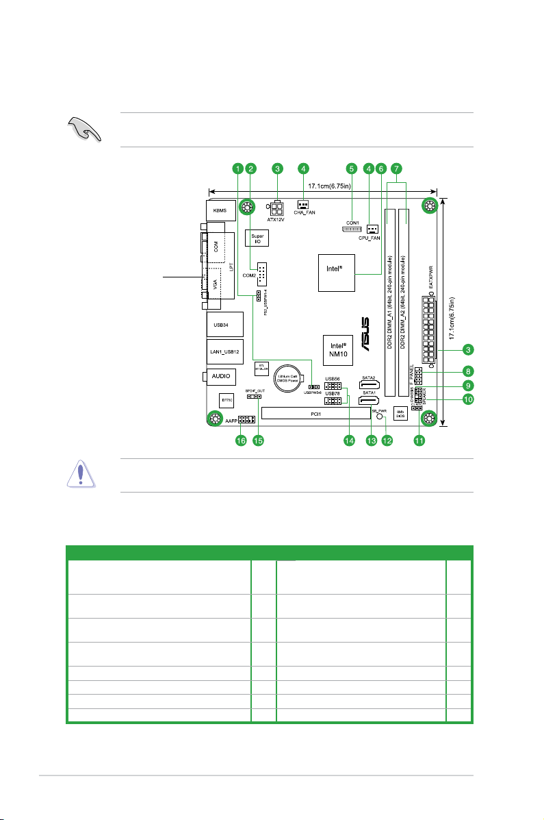
1.3 Central Processing Unit (CPU)
The motherboard comes with an onboard Intel
®
Atom™ D410 processor and a specially
designed CPU heatsink.
AT4NM10-I CPU - Atom D410
D410
AT4NM10-I
AT4NM10-I CPU fan connector
AT4NM10-I
If you need to use an additional CPU fan, connect the CPU fan cable to the connector on
the motherboard labeled CPU_FAN.
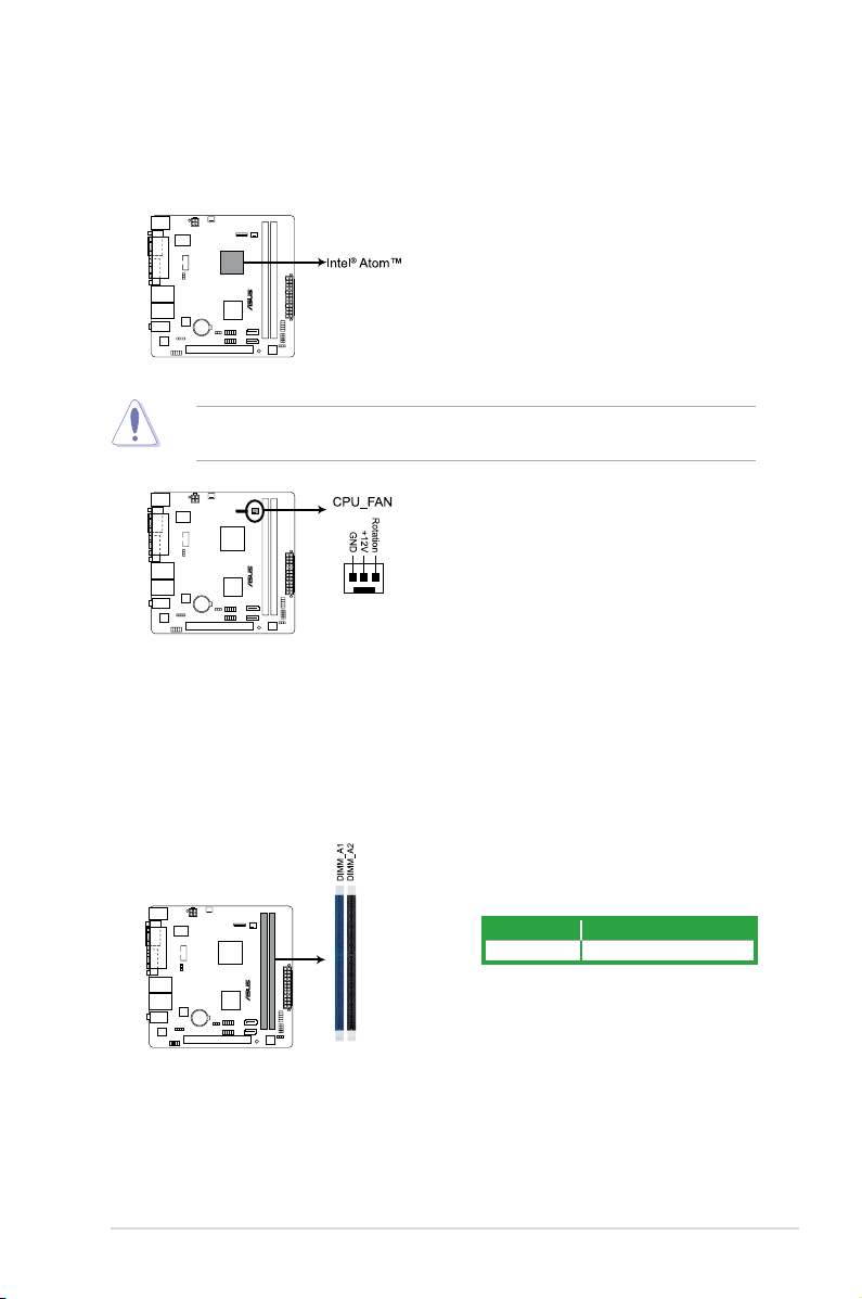
1.4 System memory
1.4.1 Overview
The motherboard comes with two Double Data Rate 2 (DDR2) Dual Inline Memory Modules
(DIMM) sockets. The gure illustrates the location of the DDR2 DIMM sockets:
AT4NM10-I 240-pin DDR2 DIMM sockets
AT4NM10-I
Channel Sockets
Channel A DIMM_A1 and DIMM_A2

ASUS AT4NM10-I 1-4
1.4.2 Memory congurations
You may install 512MB, 1GB, and 2GB unbuffered non-ECC DDR2 DIMMs into the DIMM
sockets.
• Always install DIMMs with the same CAS latency. For optimum compatibility, it is
recommended that you obtain memory modules from the same vendor.
• Due to the memory address limitation on 32-bit Windows
®
OS, when you install 4GB
or more memory on the motherboard, the actual usable memory for the OS can be
about 3GB or less. For effective use of memory, we recommend that you do any of the
following:
- Use a maximum of 3GB system memory if you are using a 32-bit Windows
®
OS.
- Install a 64-bit Windows
®
OS when you want to install 4GB memory on the
motherboard.
• When you install 4GB memory on the motherboard, the memory that the system can
detect is less than 4GB.
• This motherboard does not support DIMMs made up of 256 megabits (Mb) chips or less.
AT4NM10-I Motherboard Qualied Vendors Lists (QVL)
DDR2-667 MHz capability
Vendor Part No. Size
SS/
DS
Chip
Brand
Chip NO. Timing Voltage
DIMM
support
A* B*
A-Data M2OAD5H3J4170I1C53 2048MB DS A-Data AD20908A8A-3EG 30724 - - •
Corsair VS1GB667D2 1024MB DS Corsair MID095D62864M8CEC - - •
G.SKILL F2-5400PHU2-2GBNT 2048MB(Kit of 2) DS G.SKILL D2 64M8CCF 0815 C7173S 5-5-5-15 - •
G.SKILL F2-5300CL5D-4GBMQ 4096MB(Kit of 2) DS G.SKILL Heat-Sink Package
SN:8151030036559
5-5-5-15 - •
GEIL GX21GB5300SX 1024MB DS GEIL - 3 - •
GEIL GX22GB5300LX 2048MB DS GEIL - 5 - •
GEIL GX24GB5300LDC 2048MB DS GEIL - 5 - •
Kingston KVR667D2N5/1G
(low prole)
1024MB SS Elpida E1108AFSE-8E-F 5 1.8V •
Kingston KVR667D2N5/2G
(low prole)
2048MB DS Elpida E1108AFBG-8E-F 5 1.8V •
PSC AL7E8F73C-6E1 1024MB SS PSC A3R1GE3CFF734MAA0J 5 - •
PSC AL6E8E63J-6E1 512MB SS PSC A3R12E3JFF717B9A00 5 - •
PSC AL6E8E63J-6E1 1024MB DS PSC A3R12E3JFF717B9A01 5 - •
PSC AL8E8F73C-6E1 2048MB DS PSC A3R1GE3CFF733MAA00 5 - •
SAMSUNG M378T5263AZ3-CE6 4096MB DS K4T2G084QA-HCE6 - - •
Transcend JM667QLJ-1G 1024MB DS Elpida E5108AJBG-6E-E 5 - •
Transcend JM667QLU-2G 2048MB DS Transced TQ243PCF8T0834 5 - •
Twinmos 8D-A3JK5MPETP 512MB SS PSC A3R12E3GEF633ACAOY 5 - •
ASINT SLY2128M8-J6E 1024MB SS ASINT DDRII1208-6E 8115 - - •
ASINT SLX264M8-J6E 512MB SS ASINT DDRII6408-6E - - •
Century CENTURY 512MB 512MB SS Hynix HY5PS12821AFP-Y5 - - •
Century CENTURY 512MB 512MB SS Nanya NT5TU64M8AE-3C - - •
Century CENTURY 1G 1024MB DS Hynix HY5PS12821AFP-Y5 - - •
(continued on the next page)
1-5 Chapter 1: Product introduction
DDR2-667 MHz capability
(continued on the next page)
Vendor Part No. Size
SS/
DS
Chip
Brand
Chip NO. Timing Voltage
DIMM
support
A* B*
Century CENTURY 1G 1024MB DS Nanya NT5TU64M8AE-3C - - •
KINGBOX 512MB 667MHz 512MB SS EPD264082200-4 - - •
KINGBOX DDRII 1G 667MHz 1024MB DS EPD264082200-4 - - •
MDT MDT 1024MB 1024MB DS MDT 18D51280D-30646E 4 - •
MDT DDRII 512 PC667 512MB DS MDT 18D51201D-30726E 4 - •
TAKEMS TMS51B264C081-
665AP
512MB SS takeMS MS18T51280-3S0627D 5 - •
TAKEMS TMS51B264C081-
665QI
512MB SS takeMS MS18T51280-3 5 - •
TAKEMS TMS1GB264C081-
665AE
1024MB DS takeMS MS18T51280-3SEA07100 5 - •
TAKEMS TMS1GB264C081-
665AP
1024MB DS takeMS MS18T51280-3SP0717A 5 - •
TAKEMS TMS1GB264C081-
665QI
1024MB DS takeMS MS18T51280-3 5 - •
UMAX D46701GP3-63BJU 1024MB DS UMAX U2S12D30YP-6E - - •
UMAX D46702GP0-73BCU 2048MB DS UMAX U2S24D30TP-6E 5 - •
Vendor Part No. Size
SS/
DS
Chip
Brand
Chip NO. Timing Voltage
DIMM
support
A* B*
A-Data AD2800E001GOU 2048MB(Kit of 2) SS - - 4-4-4-12 2.0~2.1V • •
A-Data M2GVD6G314170Q1E58 1024MB DS V-Data VD29608A8A-25EG80813 - - • •
A-Data AD2800002GMU 2048MB DS Hynix - - - • •
A-Data AD2800E002GOU 4096MB(Kit of 2) DS - - 4-4-4-12 1.9~2.1V • •
Corsair XMS2-6400 1024MB DS Corsair - 4 - • •
Corsair XMS2-6400 1024MB DS Corsair - 5 - • •
Corsair CM2X2048-6400C5DHX 4096MB(Kit of 2) DS - - 5 - • •
Corsair CM2X2048-6400C5 4096MB(Kit of 2) DS - - 5 - • •
Crucial BL12864AL80A.8FE5(EPP) 2048MB(kit of 2) SS - - 4-4-4-12 - • •
Crucial BL25664AL80A.16FE5(EPP) 4096MB(kit of 2) DS - - 4-4-4-12 - • •
Crucial BL25664AR80A.16FE5(EPP) 4096MB(kit of 2) DS - - 4-4-4-12 - • •
G.SkiLL F2-6400PHU2-2GBNR 1024MB SS - - 5-5-5-15 1.9-2.0V • •
G.SKILL F2-6400CL5D-1GBNQ 512MB SS G.SKILL Heat-Sink Package
SN:8151030036642
5-5-5-15 - • •
G.SKILL F2-6400CL4D-2GBPK 1024MB DS G.SKILL - 4 - • •
G.SKILL F2-6400CL5D-2GBNQ 1024MB DS G.SKILL - 5 - • •
G.SKILL F2-6400CL4D-4GBPK 2048MB DS G.SKILL - 4 - • •
G.SKILL F2-6400CL5D-4GBPQ 2048MB DS G.SKILL - 5 - • •
G.SkiLL F2-6400CL6D-4GBMQ 4096MB(Kit of 2 ) DS - - 6-6-6-18 1.8-1.9V • •
G.SKILL F2-6400CL6Q-16GMQ 4096MB DS - - 5 - • •
GEIL GB22GB6400C4DC 1024MB DS GEIL GL2L64M088BA30EB 5 - • •
GEIL GB22GB6400C5DC 1024MB DS GEIL GL2L64M088BA30EB 5 - • •
GEIL GB24GB6400C4QC 1024MB DS GEIL GL2L64M088BA30EB 4 - • •
GEIL GB24GB6400C5QC 1024MB DS GEIL GL2L64M088BA30EB 5 - • •
GEIL GE22GB800C4DC 1024MB DS GEIL - 4 - • •
DDR2-800 MHz capability
 Loading...