


A8N-SLI SE

Motherboard
A8N-SLI SE
ii
Copyright © 2005 ASUSTeK COMPUTER INC. All Rights Reserved.
No part of this manual, including the products and software described in it, may be reproduced,
transmitted, transcribed, stored in a retrieval system, or translated into any language in any form
or by any means, except documentation kept by the purchaser for backup purposes, without the
express written permission of ASUSTeK COMPUTER INC. (“ASUS”).
Product warranty or service will not be extended if: (1) the product is repaired, modified or
altered, unless such repair, modification of alteration is authorized in writing by ASUS; or (2)
the serial number of the product is defaced or missing.
ASUS PROVIDES THIS MANUAL “AS IS” WITHOUT WARRANTY OF ANY KIND, EITHER
EXPRESS OR IMPLIED, INCLUDING BUT NOT LIMITED TO THE IMPLIED WARRANTIES
OR CONDITIONS OF MERCHANTABILITY OR FITNESS FOR A PARTICULAR PURPOSE.
IN NO EVENT SHALL ASUS, ITS DIRECTORS, OFFICERS, EMPLOYEES OR AGENTS BE
LIABLE FOR ANY INDIRECT, SPECIAL, INCIDENTAL, OR CONSEQUENTIAL DAMAGES
(INCLUDING DAMAGES FOR LOSS OF PROFITS, LOSS OF BUSINESS, LOSS OF USE
OR DATA, INTERRUPTION OF BUSINESS AND THE LIKE), EVEN IF ASUS HAS BEEN
ADVISED OF THE POSSIBILITY OF SUCH DAMAGES ARISING FROM ANY DEFECT OR
ERROR IN THIS MANUAL OR PRODUCT.
SPECIFICATIONS AND INFORMATION CONTAINED IN THIS MANUAL ARE FURNISHED
FOR INFORMATIONAL USE ONLY, AND ARE SUBJECT TO CHANGE AT ANY TIME
WITHOUT NOTICE, AND SHOULD NOT BE CONSTRUED AS A COMMITMENT BY
ASUS. ASUS ASSUMES NO RESPONSIBILITY OR LIABILITY FOR ANY ERRORS OR
INACCURACIES THAT MAY APPEAR IN THIS MANUAL, INCLUDING THE PRODUCTS
AND SOFTWARE DESCRIBED IN IT.
Products and corporate names appearing in this manual may or may not be registered
trademarks or copyrights of their respective companies, and are used only for identification or
explanation and to the owners’ benefit, without intent to infringe.
E225 2
Revi s e d Edi t i o n V1
Sept e m b er 2 0 0 5

iii
Contents
Notices ...............................................................................................viii
Safety information .............................................................................. ix
About this guide ................................................................................... x
How this guide is organized ...................................................... x
Where to find more information .............................................. xi
Conventions used in this guide ................................................ xi
Typography ......................................................................................... xi
A8N-SLI SE specifications summary ....................................................xii
Chapter 1: Product introduction
1.1 Welcome! .............................................................................. 1-1
1.2 Package contents ................................................................. 1-1
1.3 Special features .................................................................... 1-2
1.3.1 Product highlights ................................................... 1-2
1.3.2 ASUS Proactive features ........................................ 1-4
1.3.3 Innovative ASUS features ....................................... 1-5
Chapter 2: Hardware information
2.1 Before you proceed .............................................................. 2-1
2.2 Motherboard overview .......................................................... 2-2
2.2.1 Placement direction ................................................ 2-2
2.2.2 Screw holes ............................................................. 2-2
2.2.3 Motherboard layout ................................................ 2-3
2.2.4 Layout Contents ..................................................... 2-4
2.3 Central Processing Unit (CPU) .............................................. 2-6
2.3.1 Overview ................................................................. 2-6
2.3.2 Installing the CPU .................................................... 2-6
2.3.3 Installing the heatsink and fan ................................ 2-8
2.4 System memory .................................................................. 2-11
2.4.1 Overview ............................................................... 2-11
2.4.2 Memory Configurations ......................................... 2-11
2.4.3 Installing a DIMM ...................................................2-14
2.4.4 Removing a DIMM .................................................. 2-14
2.5 Expansion slots ................................................................... 2-15
2.5.1 Installing an expansion card .................................. 2-15

iv
Contents
2.5.2 Configuring an expansion card .............................. 2-15
2.5.3 Interrupt assignments ........................................... 2-16
2.5.4 PCI slots ................................................................ 2-16
2.5.5 Two PCI Express x16 slots .................................... 2-17
2.5.6 PCI Express x1 slot ............................................... 2-17
2.5.7 Universal PCIe slot (PCI Express x4 slot) .............. 2-17
2.6 Jumpers .............................................................................. 2-18
2.7 Connectors .........................................................................2-19
2.7.1 Rear panel connectors .......................................... 2-19
2.7.2 Internal connectors ............................................... 2-21
Chapter 3: Powering up
3.1 Starting up for the first time ................................................ 3-1
3.2 Powering off the computer ................................................... 3-2
3.2.1 Using the OS shut down function ........................... 3-2
3.2.2 Using the dual function power switch ..................... 3-2
Chapter 4: BIOS setup
4.1 Managing and updating your BIOS ........................................ 4-1
4.1.1 Creating a bootable floppy disk .............................. 4-1
4.1.2 Updating the BIOS ................................................... 4-2
4.1.3 Saving the current BIOS file .................................... 4-4
4.1.4 ASUS CrashFree BIOS 2 utility ................................ 4-5
4.1.5 ASUS EZ Flash utility ............................................... 4-7
4.1.6 ASUS Update utility ................................................ 4-8
4.2 BIOS setup program ............................................................ 4-11
4.2.1 BIOS menu screen ................................................. 4-12
4.2.2 Menu bar ............................................................... 4-12
4.2.3 Legend bar ............................................................ 4-13
4.2.4 Menu items ........................................................... 4-13
4.2.5 Sub-menu items .................................................... 4-13
4.2.6 Configuration fields ............................................... 4-13
4.2.7 Pop-up window ...................................................... 4-14
4.2.8 General help .......................................................... 4-14
4.3 Main menu ........................................................................... 4-15

v
Contents
4.3.1 System Time ........................................................ 4-15
4.3.2 System Date ........................................................ 4-15
4.3.3 Legacy Diskette A ...............................................4-15
4.3.4 Primary and Secondary IDE Master/Slave ............. 4-16
4.3.5 First, Second, Third, Fourth SATA Master ............4-18
4.3.6 HDD SMART Monitoring ......................................... 4-19
4.3.7 Installed Memory ................................................... 4-19
4.3.8 Usable Memory ...................................................... 4-19
4.4 Advanced menu .................................................................. 4-20
4.4.1 CPU Configuration ................................................. 4-20
4.4.2 PCI PnP .................................................................. 4-23
4.4.3 Onboard Devices Configuration ............................. 4-24
4.4.4 SLI Configuration ................................................... 4-29
4.4.5 JumperFree Configuration ..................................... 4-30
4.4.6 PEG Link Mode ....................................................... 4-32
4.5 Power menu ........................................................................ 4-34
4.5.1 ACPI Suspend Type ............................................... 4-34
4.5.2 ACPI APIC Support ................................................ 4-34
4.5.3 APM Configuration ................................................4-35
4.5.4 Hardware Monitor .................................................. 4-37
4.6 Boot menu .......................................................................... 4-39
4.6.1 Boot Device Priority .............................................. 4-39
4.6.2 Removable Drives .................................................. 4-40
4.6.3 Hard Disk Drives .................................................... 4-40
4.6.4 Boot Settings Configuration ................................4-41
4.6.5 Security ................................................................. 4-43
4.7 Exit menu ............................................................................ 4-45
Chapter 5: Software support
5.1 Installing an operating system .............................................. 5-1

vi
5.2 Support CD information ........................................................ 5-1
5.2.1 Running the support CD .......................................... 5-1
5.2.2 Drivers menu ........................................................... 5-2
5.2.3 Utilities menu .......................................................... 5-3
5.2.4 Manuals menu ......................................................... 5-5
5.2.5 ASUS Contact information ...................................... 5-6
5.2.6 Other information ................................................... 5-6
5.3 Software information ............................................................ 5-9
5.3.1 ASUS MyLogo2™ ..................................................... 5-9
5.3.2 Audio configurations ............................................. 5-11
5.3.3 Using the NVIDIA® Firewall™ .................................. 5-17
5.4 RAID configurations ............................................................ 5-20
5.4.1 Installing hard disks ............................................... 5-21
5.4.2 NVIDIA® RAID configurations ................................. 5-22
5.5 Creating a RAID driver disk ................................................. 5-29
5.6 Cool ʻnʼ Quiet!™ Technology ............................................... 5-30
5.6.1 Enabling Cool ʻnʼ Quiet!™ Technology ................... 5-30
5.6.2 Launching the Cool ʻnʼ Quiet!™ software .............. 5-31
5.7 Using the NVIDIA® nTune™ utility ....................................... 5-32
5.7.1 Managing your nForce™ system ............................ 5-32
5.7.2 Clock control ......................................................... 5-33
5.7.3 Voltage/Fan control .............................................. 5-33
5.7.4 Information ........................................................... 5-34
5.7.5 Other options ........................................................ 5-34
5.8 Using the ASUS AI Selector utility ...................................... 5-35
5.8.1 Launching the ASUS AI Selector ........................... 5-35
5.8.2 Using the SLI mode ............................................... 5-36
Chapter 6: SLI™ technology support
6.1 Overview ............................................................................... 6-1
6.2 Dual graphics card setup ...................................................... 6-2
6.2.1 Installing SLI-ready graphics cards .......................... 6-2
Contents

vii
6.2.2 Installing the device drivers .................................... 6-5
6.2.3 Installing the ASUS AI Selector utility ..................... 6-5
6.2.4 Enabling the multi-GPU feature in Windows ............ 6-6
6.2.5 Setting the ASUS AI Selector utility ....................... 6-8
viii
Notices
Fed er al Co mm un ica ti on s C om mi ssi on S tat em en t
This device complies with Part 15 of the FCC Rules. Operation is subject to
the following two conditions:
•
This device may not cause harmful interference, and
•
This device must accept any interference received including
interference that may cause undesired operation.
This equipment has been tested and found to comply with the limits for a
Class B digital device, pursuant to Part 15 of the FCC Rules. These limits
are designed to provide reasonable protection against harmful interference
in a residential installation. This equipment generates, uses and can radiate
radio frequency energy and, if not installed and used in accordance with
manufacturerʼs instructions, may cause harmful interference to radio
communications. However, there is no guarantee that interference will
not occur in a particular installation. If this equipment does cause harmful
interference to radio or television reception, which can be determined by
turning the equipment off and on, the user is encouraged to try to correct
the interference by one or more of the following measures:
•
Reorient or relocate the receiving antenna.
•
Increase the separation between the equipment and receiver.
•
Connect the equipment to an outlet on a circuit different from that to
which the receiver is connected.
•
Consult the dealer or an experienced radio/TV technician for help.
Can ad ia n D ep ar tme nt o f C om mu nic at io ns St at eme nt
This digital apparatus does not exceed the Class B limits for radio noise
emissions from digital apparatus set out in the Radio Interference
Regulations of the Canadian Department of Communications.
This class B digital apparatus complies with Canadian
ICES-003.
The use of shielded cables for connection of the monitor to the graphics
card is required to assure compliance with FCC regulations. Changes
or modifications to this unit not expressly approved by the party
responsible for compliance could void the userʼs authority to operate
this equipment.
ix
Safety information
Ele ct ri cal s af ety
•
To prevent electrical shock hazard, disconnect the power cable from
the electrical outlet before relocating the system.
•
When adding or removing devices to or from the system, ensure that
the power cables for the devices are unplugged before the signal cables
are connected. If possible, disconnect all power cables from the existing
system before you add a device.
•
Before connecting or removing signal cables from the motherboard,
ensure that all power cables are unplugged.
•
Seek professional assistance before using an adapter or extension cord.
These devices could interrupt the grounding circuit.
•
Make sure that your power supply is set to the correct voltage in your
area. If you are not sure about the voltage of the electrical outlet you
are using, contact your local power company.
•
If the power supply is broken, do not try to fix it by yourself. Contact a
qualified service technician or your retailer.
Ope ra ti on sa fe ty
•
Before installing the motherboard and adding devices on it, carefully
read all the manuals that came with the package.
•
Before using the product, make sure all cables are correctly connected
and the power cables are not damaged. If you detect any damage,
contact your dealer immediately.
•
To avoid short circuits, keep paper clips, screws, and staples away from
connectors, slots, sockets and circuitry.
•
Avoid dust, humidity, and temperature extremes. Do not place the
product in any area where it may become wet.
•
Place the product on a stable surface.
•
If you encounter technical problems with the product, contact a
qualified service technician or your retailer.
x
About this guide
This user guide contains the information you need when installing and
configuring the motherboard.
How t hi s g ui de is o rg ani ze d
This manual contains the following parts:
• Chap t e r 1: P r o duct i n trod u c t ion
This chapter describes the features of the motherboard and the new
technology it supports.
• Chap t e r 2: H a r dwar e i nfor m a t ion
This chapter lists the hardware setup procedures that you have to
perform when installing system components. It includes description of
the switches, jumpers, and connectors on the motherboard.
• Chap t e r 3: P o w erin g u p
This chapter describes the power up sequence, and the ways of
shutting down the system.
• Chap t e r 4: B I O S se t u p
This chapter tells how to change system settings through the BIOS
Setup menus. Detailed descriptions of the BIOS parameters are also
provided.
• Chap t e r 5: S o f twar e s uppo r t
This chapter describes the contents of the support CD that comes
with the motherboard package.
• Chap t e r 6: N V I DIA® SLI ™ t echn o l o gy s u p p ort
This chapter tells how to install SLI-ready PCI Express graphics cards.
• Appe n d i x: I n s t alla t i o n op t i o ns
This appendix describes how to install optional accessories to your
motherboard.
xi
Con ve nt ion s us ed in t his g ui de
To make sure that you perform certain tasks properly, take note of the
following symbols used throughout this manual.
Typography
DANGER/WARNING: Information to prevent injury to yourself
when trying to complete a task.
CAUTION: Information to prevent damage to the components
when trying to complete a task.
NOTE: Tips and additional information to help you complete a
task.
IMPORTANT: Instructions that you MUST follow to complete a
task.
Bold text Indicates a menu or an item to select
Italics
Used to emphasize a word or a phrase
<Key> Keys enclosed in the less-than and greater-than sign means
that you must press the enclosed key
Example: <Enter> means that you must press the Enter or
Return key
<Key1+Key2+Key3> If you must press two or more keys simultaneously, the
key names are linked with a plus sign (+)
Example: <Ctrl+Alt+Del>
Command
Means that you must type the command exactly as shown,
then supply the required item or value enclosed in
brackets
Example: At the DOS prompt, type the command line:
awdflash A8NSLISE.ROM
Whe re t o f in d mor e in for ma ti on
Refer to the following sources for additional information and for product
and software updates.
1. A S U S we b s i tes
The ASUS website provides updated information on ASUS hardware
and software products. Refer to the ASUS contact information.
2. O p t iona l d ocum e n t atio n
Your product package may include optional documentation, such as
warranty flyers, that may have been added by your dealer. These
documents are not part of the standard package.
xii
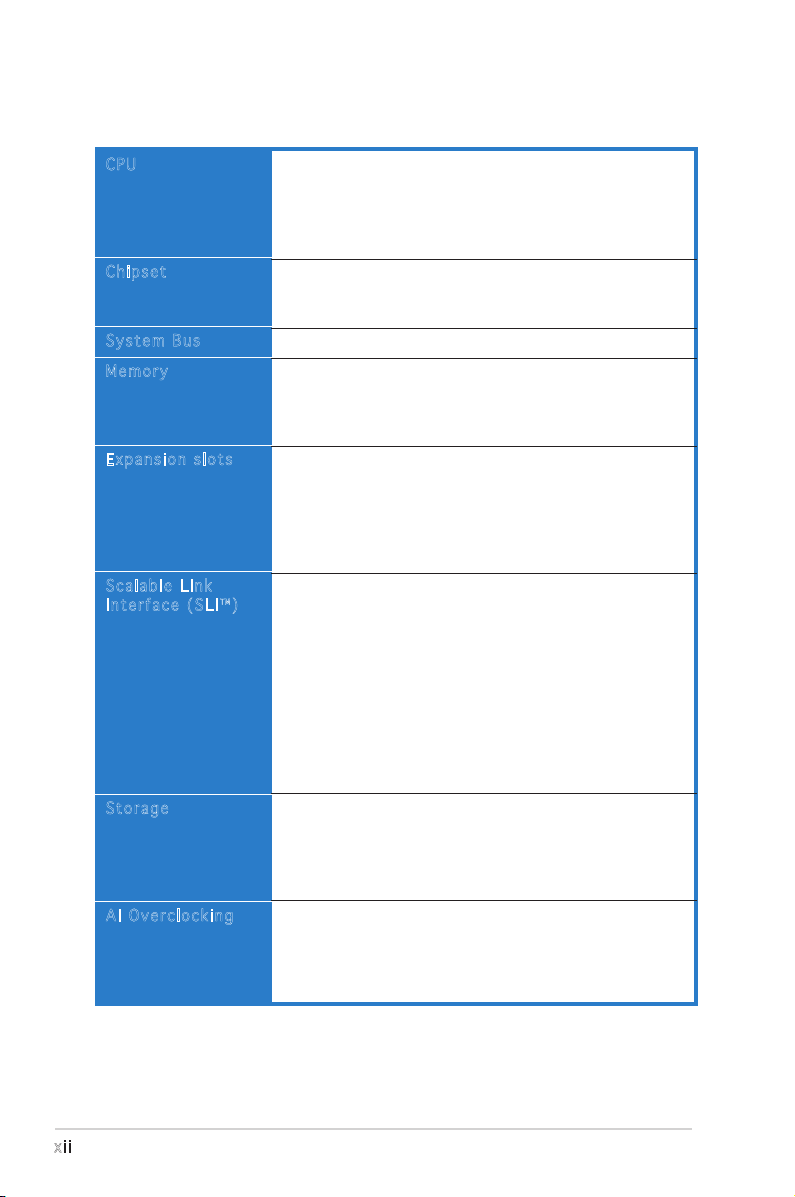
A8N-SLI SE specifications summary
(continued on the next page)
CPU
Chipset
System Bus
Memory
Expansion slots
Scalable Link
Interface (SLI™)
Storage
AI Overclocking
Socket 939 for AMD Athlon™ 64FX/AMD Athlon™ 64/
AMD Athlon 64X2 Processor
Supports AMD 64 architecture that enables simultaneous
32-bit and 64-bit architecture
Supports AMD® Cool ʻnʼ Quiet! Technology
NVIDIA® nForce™ 4 SLI
Supports NVIDIA® Scalable Link Interface™ (SLI)
technology
1600/2000 MT per second
Dual-channel memory architecture
4 x 184-pin DIMM sockets support ECC/non-ECC
unbufferred 400/333/266 MHz DDR memory modules
Supports up to 4 GB system memory
2 x PCI Express x16 slots with Scalable Link Interface
(SLI™) support
1 x PCI Express x1 slot
1 x PCI Express x4 slot running at 2x bandwidth that
supports X1 and X4 add-on cards
3 x PCI slots
SLI™ mode supports:
- 2 x identical SLI™-ready PCI Express x16 graphics
cards
(Note: In SLI mode, the PCI Express x16 slots work at the
bandwidth of PCI Express x8. The combined bandwidth of
these maintain the bandwidth of PCI Express x16.)
Single card mode supports (default):
- 1 x any PCI Express x16 graphics card on the first slot
ASUS AI Selector
ASUS EZ Plug™
ASUS Two-slot thermal design
NVIDIA® nForce™ 4 SLI chipset supports:
- 2 x Ultra DMA 133/100/66/33
- 4 x Serial ATA devices
- RAID 0, RAID 1, RAID 0+1, and JBOD that spans
across the Serial ATA and Parallel ATA drives
AI NOS™ (Non-Delay Overclocking System)
ASUS AI Overclocking (Intelligent CPU frequency tuner)
ASUS PEG Link for single/dual graphics card
Fixed PCI Express/PCI/SATA frequencies
ASUS C.P.R. (CPU Parameter Recall)
xiii
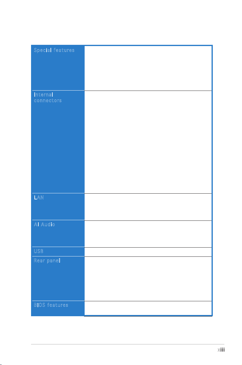
A8N-SLI SE specifications summary
Special features
Internal
connectors
LAN
AI Audio
USB
Rear panel
BIOS features
ASUS AI Selector
ASUS EZFlash
ASUS Q-Fan2
ASUS CrashFree BIOS 2
ASUS MyLogo2™
ASUS SLI Warning LED
ASUS EZ Plug
1 x Floppy disk drive connector
2 x IDE connectors
4 x Serial ATA connectors
1 x CPU fan connector
1 x Power fan connector
1 x Chassis fan connector
1 x Chipset fan connector
1 x Serial port connector (COM port)
1 x 24-pin ATX power connector
1 x 4-pin ATX 12 V power connector
1 x 4-pin ASUS EZ Plug™ connector
3 x USB 2.0 connectors for 6 additional USB 2.0 ports
1 x Internal audio connectors (CD\AUX)
1 x GAME/MIDI connector
1 x Chassis intrusion connector
1 x Front panel audio connector
System panel connector
NVIDIA® nForce™ 4 built-in Gigabit MAC with external
PHY supports:
- NV ActiveArmor
- NV Firewall
Realtek® ALC850 6-channel CODEC
1 x Coaxial S/PDIF out port
Supports Universal Audio Jack (UAJ®) Technology
Supports Audio Sensing and Enumeration Technology
Supports up to 10 USB 2.0 ports
1 x Parallel port
1 x LAN (RJ-45) port
4 x USB 2.0 ports
1 x Coaxial S/PDIF out port
1 x PS/2 keyboard port
1 x PS/2 mouse port
6-channel audio ports
4 Mb Flash ROM, Phoenix-Award BIOS, PnP, DMI2.0,
WfM2.0, SM BIOS 2.3
(continued on the next page)
xiv
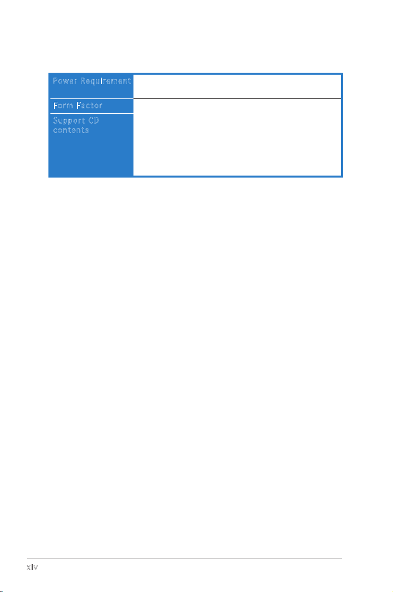
A8N-SLI SE specifications summary
Power Requirement
Form Factor
Support CD
contents
ATX power supply (with 24-pin and 4-pin 12 V plugs)
ATX 12 V 2.0 compliant
ATX form factor: 12 in x 9.6 in (30.5 cm x 24.4 cm)
Device drivers
ASUS PC Probe II
ASUS Live Update utility
ASUS CoolʼnʼQuiet! utility
Anti-virus utility (OEM version)
NVIDIA® nTune™ utility
*Specifications are subject to change without notice.

1
Product
introduction
This chapter describes the motherboard
features and the new technologies
it supports.

ASUS A8N-SLI SE
Chapter summary
1.1 Welcome! .............................................................................. 1-1
1.2 Package contents ................................................................. 1-1
1.3 Special features .................................................................... 1-2
ASUS A8N-SLI SE 1-1
1.1 Welcome!
T h a n k y o u f o r b u y i n g a n A S U S® A 8 N - S L I S E m o t h e r b o a r d !
The motherboard delivers a host of new features and latest technologies,
making it another standout in the long line of ASUS quality motherboards!
Before you start installing the motherboard, and hardware devices on it,
check the items in your package with the list below.
If any of the above items is damaged or missing, contact your retailer.
1.2 Package contents
Check your motherboard package for the following items.
Motherboard ASUS A8N-SLI SE motherboard
Cables 2 x Serial ATA signal cables
Serial ATA power cable with dual plugs
Ultra DMA/133 cable
40-conductor IDE cable
Floppy disk drive cable
Accessories I/O shield
SLI™ flexible cable
USB2.0 2-port module
Application CDs ASUS motherboard support CD
Documentation User guide
1-2 Chapter 1: Product introduction
1.3 Special features
1.3 .1 Pro du ct hi gh li ght s
Lat e st pro c es s or t ec h nol o gy
The AMD Athlon™ 64FX, Athlon™ 64 and Athlon 64x2 desktop processors
are based on AMDʼs 64-bit and 32-bit architecture, which represents the
landmark introduction of the industryʼs first x86-64 technology. These
processors provide a dramatic leap forward in compatibility, performance,
investment protection, and reduced total cost of ownership and
development. See page 2-6 for details.
Sca l ab l e L i nk Int e rf a ce ( SL I ™) t ec h nol o gy
The NVIDIA® nForce4® Scalable Link Interface (SLI™) technology allows two
graphics processing units (GPUs) in a single system. This technology takes
advantage of the PCI Express™ bus architecture and features intelligent
hardware and software solutions that allows multiple GPUs to work
together and achieve exceptional graphics performance. See Chapter 6 for
details.
Bui l t- i n N V F i rew a ll ™ an d N V Ac t iv e Arm o r™
The NVIDIA® Firewall™ (NV Firewall™) is an easy-to-use high-performance
desktop firewall application that protects your system from intruders.
Integrated into the NVIDIA® nForce4® SLI™ chipset with the NVIDIA® Gigabit
Ethernet, it provides advanced anti-computer-hacking technologies, remote
management capabilities, and a user-friendly setup wizard that improves
overall system security.
Enhancing your network security is the NVIDIA® ActiveArmor™
(NV ActiveArmor™) engine that provides advanced data packet inspection.
This innovative technology ensures that only safe data packets are passed
on the network. It boosts overall system performance by offloading the
CPU from the rigorous task of filtering data packets. See page 5-17 for
details.
AMD Co o l ʻ n ʼ Q uie t !™ Tec h no l ogy
The motherboard supports the AMD Cool ʻnʼ Quiet!™ Technology that
dynamically and automatically changes the CPU speed, voltage and amount
of power depending on the task the CPU performs. See pages 4-22 and
5-31.
ASUS A8N-SLI SE 1-3
Hyp e rT r ans p or t ™ T e ch n olo g y
HyperTransport™ Technology is a high-speed, low latency, point-to-point
link designed to increase the communication speed between integrated
circuits in computers, networking and telecommunicatons equipment up to
48 times faster than other existing technologies.
Dua l C h ann e l D DR m em o ry s up p ort
Employing the Double Data Rate (DDR) memory technology,
the motherboard supports up to 4GB of system memory using
DDR400/333/266 DIMMs. The ultra-fast 400MHz memory bus delivers the
required bandwidth for the latest 3D graphics, multimedia, and Internet
applications. See page 2-11.
Ser i al ATA II tec h no l ogy
The motherboard supports the next-generation Serial ATA 3Gb/s
technology through the Serial ATA interfaces and the NVIDIA® SLI™ chipset.
The SATA 3Gb/s specification provides twice the bandwidth of the current
Serial ATA products with a host of new features including Native Command
Queuing (NCQ), Power Management (PM) Implementation Algorithm, and
Hot Swap. Additionally, Serial ATA allows thinner, more flexible cables with
lower pin count, and reduced voltage requirement. See pages 2-21.
RAI D S o lut i on
The NVIDIA® nForce4® SLI™ allows RAID 0, RAID 1, RAID 0+1 and JBOD
configuration for four SATA and two PATA connectors. See pages 2-21 and
5-22 for details.
PCI Ex p res s ™ i nte r fa c e
The motherboard fully supports PCI Express, the latest I/O interconnect
technology that speeds up the PCI bus. PCI Express features point-to-point
serial interconnections between devices and allows higher clockspeeds by
carrying data in packets. This high speed interface is software compatible
with existing PCI specifications. See page 2-15 and 2-16 for details.
S/P D IF dig i ta l so u nd rea d y
The motherboard supports the S/PDIF Out function through the S/PDIF
interfaces on the rear panel. The S/PDIF technology turns your computer
into a high-end entertainment system with digital connectivity to powerful
audio and speaker systems. See page 2-18 for details.
1-4 Chapter 1: Product introduction
1.3 .2 ASU S Pr oac ti ve fe at ur es
AI N OS ™ (N o n- D ela y O v erc l oc k ing Sy s tem )
ASUS Non-delay Overclocking System™ (NOS) is a technology that
auto-detects the CPU loading and dynamically overclocks the CPU speed
only when needed. See page 4-30 for details.
AI A ud i o t e ch n olo g y
The motherboard supports 6-channel audio through the onboard ALC850
CODEC with 16-bit DAC, a stereo 16-bit ADC, and an AC97 2.3 compatible
multi-channel audio designed for PC multimedia systems. It also provides
Jack-Sensing function, S/PDIF out support, interrupt capability and includes
the Realtek® proprietary UAJ® (Universal Audio Jack) technology. See pages
2-18, 2-19 and 5-11 for details.
USB 2.0 te c hno log y
The motherboard implements the Universal Serial Bus (USB) 2.0
specification, dramatically increasing the connection speed from the
12 Mbps bandwidth on USB 1.1 to a fast 480 Mbps on USB 2.0. USB 2.0 is
backward compatible with USB 1.1. See page 2-18 and 2-23 for details.
Tem p er a tur e , f an, an d vo l ta g e m o ni t ori n g
The CPU temperature is monitored by the ASIC (integrated in the Winbond
Super I/O) to prevent overheating and damage. The system fan rotations
per minute (RPM) is monitored for timely failure detection. The ASIC
monitors the voltage levels to ensure stable supply of current for critical
components. See section “4.5.4 Hardware Monitor” on page 4-37.
ASUS A8N-SLI SE 1-5
1.3 .3 Inn ov at ive A SU S f ea tu res
ASU S A I Se l ec t or
The AI Selector allows you to set the video card mode of your system. This
utility works when you have two graphics cards installed in your system.
See page 5-35 for details.
ASU S E Z Pl u g™
This patented ASUS technology is a 4-pin auxiliary +12V connector that
is designed to maintain the voltage integrity of your system. This plug
guarantees adequate supply of power to the motherboard and other
installed peripherals. See page 6-4 for illustration.
ASU S T w o-s l ot the r ma l de s ig n
The motherboard is designed with one PCI Express x1 slots and PCI
Express x4 slots placed between the PCI Express x16 slots allowing an
increase in airflow between the two PCI Express x16 graphics cards. This
special design permits more room for ventilation thus lowering the overall
system temperature.
Cra s hF r ee B IO S 2
This feature allows you to restore the original BIOS data from the support
CD in case when the BIOS codes and data are corrupted. This protection
eliminates the need to buy a replacement ROM chip. See page 4-5 for
details.
ASU S Q - Fan 2 te chn o log y
The ASUS Q-Fan2 technology smartly adjusts the fan speeds according to
the system loading to ensure quiet, cool, and efficient operation. See page
4-37 for details.
ASU S M y Log o 2™
This new feature present in the motherboard allows you to personalize and
add style to your system with customizable boot logos. See page 5-9 for
details.

1-6 Chapter 1: Product introduction

2
Hardware
information
This chapter lists the hardware setup
procedures that you have to perform
when installing system components.
It includes description of the jumpers
and connectors on the motherboard.

ASUS A8N-SLI SE
Chapter summary
2.1 Before you proceed .............................................................. 2-1
2.2 Motherboard overview .......................................................... 2-2
2.3 Central Processing Unit (CPU) .............................................. 2-6
2.4 System memory .................................................................. 2-11
2.5 Expansion slots ................................................................... 2-14
2.6 Jumpers .............................................................................. 2-17
2.7 Connectors .........................................................................2-18
ASUS A8N-SLI SE 2-1
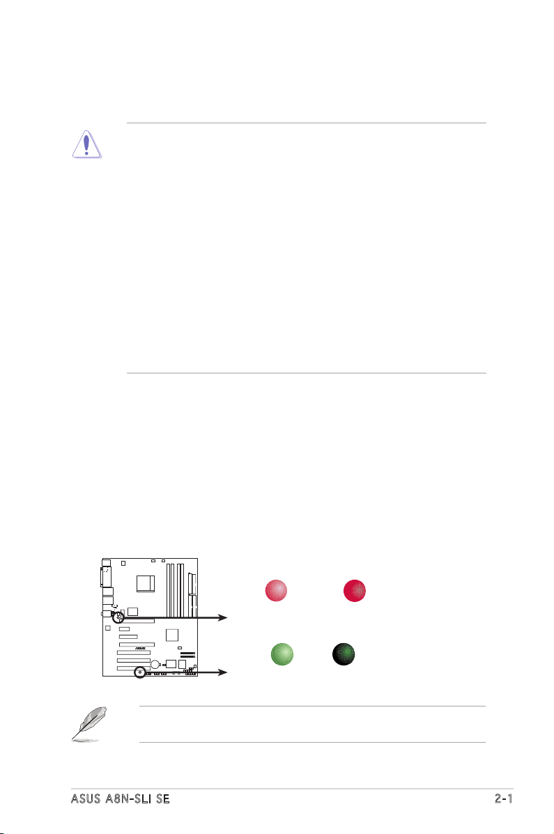
Onboard LED
The motherboard comes with a standby power LED that lights up to
indicate that the system is ON, in sleep mode, or in soft-off mode.
This is a reminder that you should shut down the system and unplug
the power cable before removing or plugging in any motherboard
component. The illustration below shows the location of the onboard
LED.
The red warning LED lights up when you installed two graphics card
but did not connect the ASUS EZ Plug™. The illustration below shows
the location of the onboard LEDs.
2.1 Before you proceed
Take note of the following precautions before you install motherboard
components or change any motherboard settings.
• Make sure that your power supply unit (PSU) can provide at least
the minimum power required by your system. See “7. ATX power
connectors” on page 2-25 for details.
• Unplug the power cord from the wall socket before touching any
component.
• Use a grounded wrist strap or touch a safely grounded object or
to a metal object, such as the power supply case, before handling
components to avoid damaging them due to static electricity
• Hold components by the edges to avoid touching the ICs on them.
• Whenever you uninstall any component, place it on a grounded
antistatic pad or in the bag that came with the component.
• Before you install or remove any component, ensure that the ATX
power supply is switched off or the power cord is detached from
the power supply. Failure to do so may cause severe damage to the
motherboard, peripherals, and/or components.
A8N-SLI SE
®
A8N-SLI SE Onboard LED
SB_PWR
ON
Standby
Power
OFF
Powered
Off
WARN_LED
When use 2 Graphics
but do not plug EZ-PLU
G
ON OFF
When use 2 Graphics
but do plug EZ-PLUG
If you are using a 24-pin power connector, you may ignore the warning
LED.
2-2 Chapter 2: Hardware information
2.2 Motherboard overview
Before you install the motherboard, study the configuration of your chassis
to ensure that the motherboard fits into it.
Make sure to unplug the power cord before installing or removing the
motherboard. Failure to do so can cause you physical injury and damage
motherboard components.
Do not overtighten the screws! Doing so can damage the motherboard.
2.2 .1 Pla ce me nt di re cti on
When installing the motherboard, make sure that you place it into the
chassis in the correct orientation. The edge with external ports goes to the
rear part of the chassis as indicated in the image below.
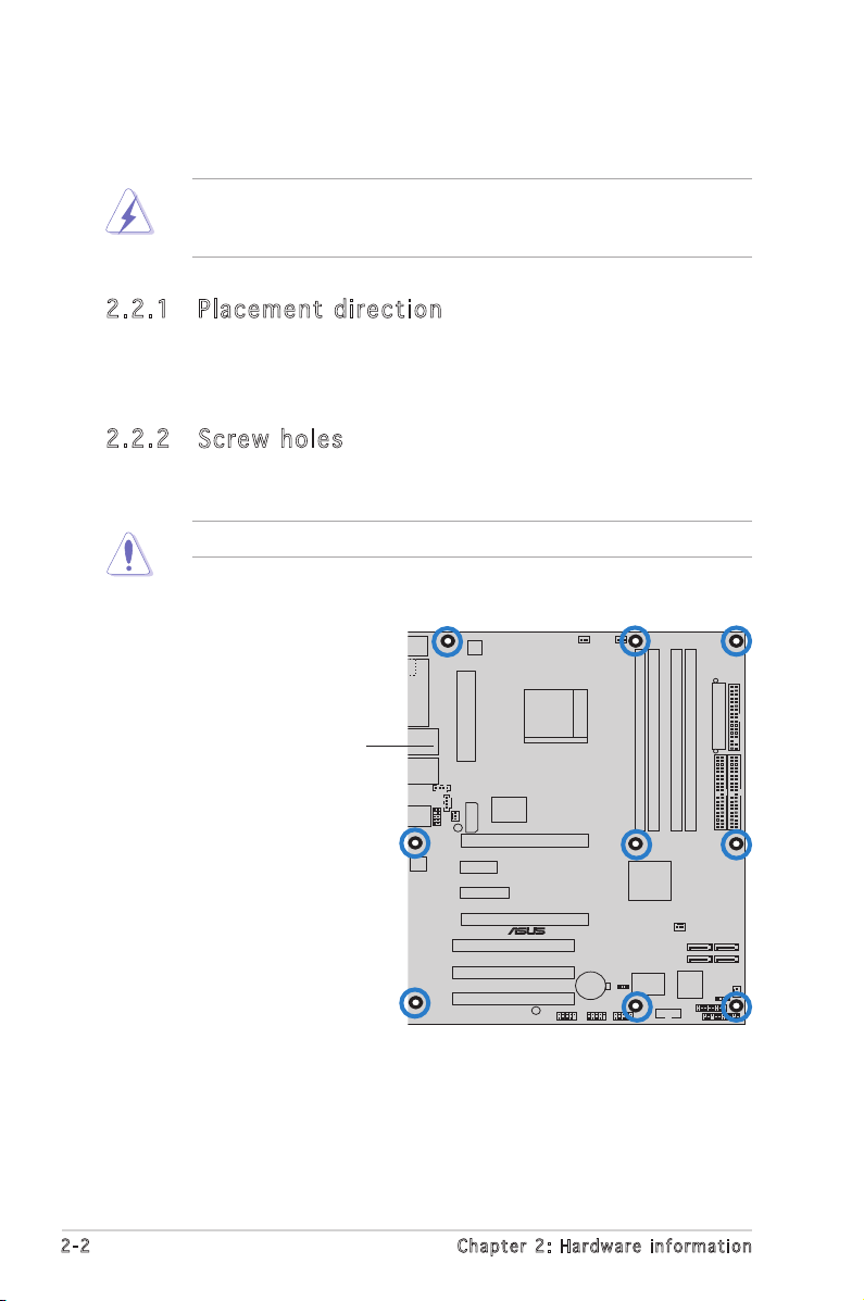
2.2 .2 Scr ew h ole s
Place nine (9) screws into the holes indicated by circles to secure the
motherboard to the chassis.
A8N-SLI SE
®
Place this side towards
the rear of the chassis
ASUS A8N-SLI SE 2-3
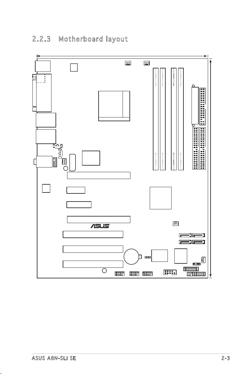
2.2 .3 Mot he rb oar d la you t
Bottom:Mic In
Center:Line Out
To
p:Line In
PANEL
A8N-SLI SE
R
CR2032 3V
Lithium Cell
CMOS Power
AUX
FP_AUDIO
GAME
CHASSIS
PRI_IDE
SEC_IDE
EATXPWR
COM1
24.5cm (9.6in)
30.5cm (12.0in)
CPU_FAN
Socket 939
DDR DIMM_B1 (64 bit,184-pin module)
DDR DIMM_A1 (64 bit,184-pin module)
DDR DIMM_A2 (64 bit,184-pin module)
DDR DIMM_B2 (64 bit,184-pin module)
CHA2_FAN
F_USB12
PWR_FAN
FLOPPY
Super
I/O
4Mb
BIOS
PS/2KBMS
T: Mouse
B: Keyboard
PARALLEL PORT
SPDIF_O
LAN_USB34
CD
WARN_LED
EZ_PLUG
ALC850
PCIEX16_1
PCIEX1_1
PCIEX16_2
PCI1
PCI2
PCI3
Gigabit PHY
CLRTC
USB78 USB56 USB910
SATA1SATA2
SATA3SATA4
CHA1_FAN
AT
X12V
NVIDIA
nForce4 SLI
CHIP_FAN
SB_PWR
PCIEX4_1
2-4 Chapter 2: Hardware information
2.2 .4 Lay ou t Con te nt s
Slots Page
1. DDR DIMM slots 2-11
2. PCI slots 2-16
3. PCI Express x16 slot 2-17
4. PCI Express x1 slot 2-17
5. PCI Express x4 slot 2-17
Jumpers Page
1. Clear RTC RAM (3-pin CLRTC1) 2-18
Rear panel connectors Page
1. PS/2 mouse port (green) 2-19
2. Parallel port 2-19
3. LAN (RJ-45) port 2-19
4. Line In port (light blue) 2-19
5. Line Out port (lime) 2-19
6. Microphone port (pink) 2-19
7. USB 2.0 ports 3 and 4 2-19
8. USB 2.0 ports 1 and 2 2-19
9. Coaxial S/PDIF out port 2-19
10. PS/2 keyboard port (purple) 2-20
ASUS A8N-SLI SE 2-5
Internal connectors Page
1. Floppy disk drive connector (34-1 pin FLOPPY) 2-21
2. IDE connector (40-1 pin PRI_IDE, 40-1 pin SEC_IDE) 2-21
3. nForce 4 Serial ATA connectors (7-pin SATA1, SATA2, SATA3, SATA4) 2-22
4. CPU, Chassis, Chipset and Power fan connectors(3-pin CPU_FAN, 2-23
3-pin CHA2_FAN, 3-pin CHIP_FAN, 3-pin PWR_FAN, 3-pin CHA1_FAN)
5. Serial port connector (10-1 pin COM1) 2-24
6. USB headers (10-1 USB56, USB78, USB910) 2-24
7 ATX power connectors (24-pin EATXPWR1, 4-pin ATX12V1, 4-pin EZ_PLUG) 2-25
8. Internal audio connectors (4-pin CD, AUX) 2-26
9. GAME/MIDI connector (16-1 pin GAME) 2-26
10. Chassis intrusion connector (4-1 pin CHASSIS) 2-27
11. Front panel audio connector (10-1 pin FP_AUDIO) 2-27
12. System panel connectors (20-1 pin PANEL) 2-28
- System Power LED (Green 3-pin PLED)
- Hard Disk activity (Red 2-pin IDE_LED)
- System warning speaker (Orange 4-pin SPEAKER)
- Power/Soft-off button(Yellow 2-pin PWRSW)
- Reset switch (Blue 2-pin RESET)
2-6 Chapter 2: Hardware information
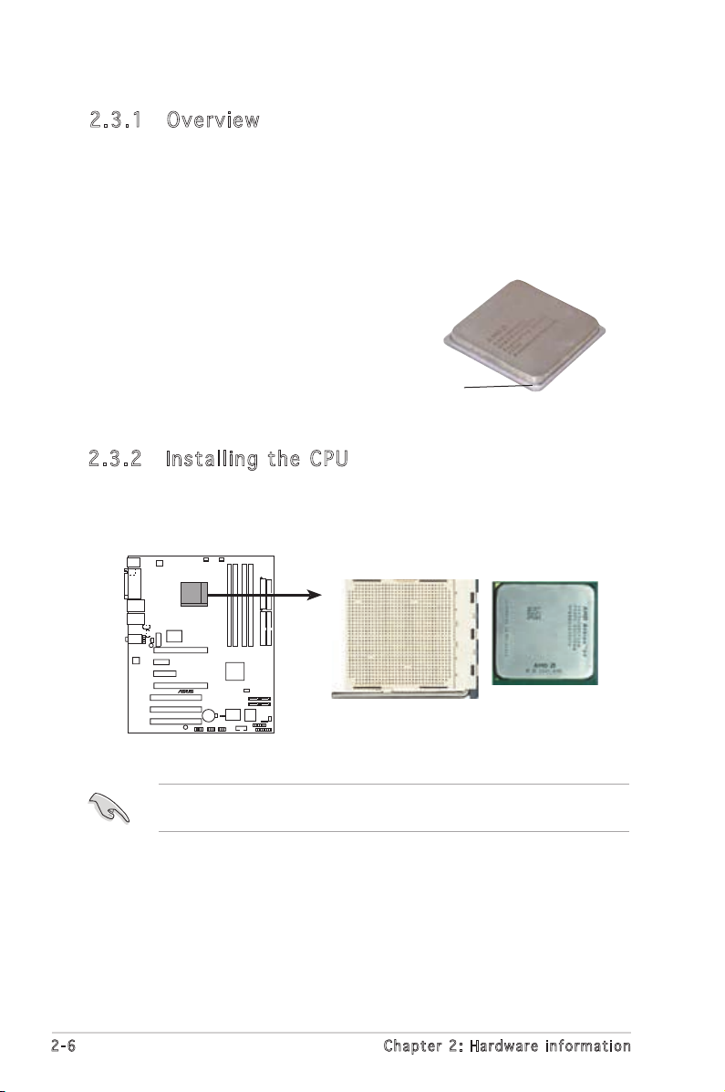
2.3 .2 Ins ta ll ing t he CP U
To install a CPU:
1. Locate the CPU socket on the motherboard.
2.3 Central Processing Unit (CPU)
2.3 .1 Ove rv ie w
The motherboard comes with a surface mount 939-pin Zero Insertion Force
(ZIF) socket designed for the AMD Athlon™ 64FX, AMD Athlon™ 64 or AMD
Athlon™ 64X2 processor.
The 128-bit-wide data paths of these processors can run applications
faster than processors with only 32-bit or 64-bit wide data paths.
Before installing the CPU, make sure that the socket box is facing
towards you and the load lever is on your left.
Take note of the marked corner (with
gold triangle) on the CPU. This mark
should match a specific corner on the
socket to ensure correct installation.
Gold triangle
A8N-SLI SE
®
A8N-SLI SE CPU Socket 939
 Loading...