


A7V600 SE
User Guide
Motherboard

E1537
First Edition V1
January 2004
Copyright © 2004 ASUSTeK COMPUTER INC. All Rights Reserved.
No part of this manual, including the products and software described in it, may be reproduced, transmitted, transcribed, stored in a retrieval system, or translated into any language in any form or by any means, except documentation kept by the purchaser for backup purposes, without the express written permission of ASUSTeK COMPUTER INC. (“ASUS”).
Product warranty or service will not be extended if: (1) the product is repaired, modified or altered, unless such repair, modification of alteration is authorized in writing by ASUS; or (2) the serial number of the product is defaced or missing.
ASUS PROVIDES THIS MANUAL “AS IS” WITHOUT WARRANTY OF ANY KIND, EITHER EXPRESS OR IMPLIED, INCLUDING BUT NOT LIMITED TO THE IMPLIED WARRANTIES OR CONDITIONS OF MERCHANTABILITY OR FITNESS FOR A PARTICULAR PURPOSE. IN NO EVENT SHALL ASUS, ITS DIRECTORS, OFFICERS, EMPLOYEES OR AGENTS BE LIABLE FOR ANY INDIRECT, SPECIAL, INCIDENTAL, OR CONSEQUENTIAL DAMAGES (INCLUDING DAMAGES FOR LOSS OF PROFITS, LOSS OF BUSINESS, LOSS OF USE OR DATA, INTERRUPTION OF BUSINESS AND THE LIKE), EVEN IF ASUS HAS BEEN ADVISED OF THE POSSIBILITY OF SUCH DAMAGES ARISING FROM ANY DEFECT OR ERROR IN THIS MANUAL OR PRODUCT.
SPECIFICATIONS AND INFORMATION CONTAINED IN THIS MANUAL ARE FURNISHED FOR INFORMATIONAL USE ONLY, AND ARE SUBJECT TO CHANGE AT ANY TIME WITHOUT NOTICE, AND SHOULD NOT BE CONSTRUED AS A COMMITMENT BY ASUS. ASUS ASSUMES NO RESPONSIBILITY OR LIABILITY FOR ANY ERRORS OR INACCURACIES THAT MAY APPEAR IN THIS MANUAL, INCLUDING THE PRODUCTS AND SOFTWARE DESCRIBED IN IT.
Products and corporate names appearing in this manual may or may not be registered trademarks or copyrights of their respective companies, and are used only for identification or explanation and to the owners’ benefit, without intent to infringe.
ii

Contents
Notices ............................................................................................ |
v |
Safety information .......................................................................... |
vi |
About this guide ............................................................................. |
vii |
ASUS contact information ............................................................ |
viii |
A7V600 SE specifications summary .............................................. |
ix |
Chapter 1: Product introduction
1.1 |
Welcome! ........................................................................... |
1-2 |
|
1.2 |
Package contents ............................................................... |
1-2 |
|
1.3 |
Special Features ................................................................ |
1-3 |
|
|
1.3.1 |
Product highlights ................................................... |
1-3 |
|
1.3.2 |
Value-added solutions ............................................ |
1-5 |
1.4 |
Motherboard components .................................................. |
1-6 |
|
|
Core specifications ............................................................. |
1-7 |
|
1.5 |
Motherboard layout ............................................................ |
1-9 |
|
1.6 |
Before you proceed .......................................................... |
1-10 |
|
1.7 |
Motherboard installation .................................................... |
1-11 |
|
|
1.7.1 |
Placement direction .............................................. |
1-11 |
|
1.7.2 |
Screw holes .......................................................... |
1-11 |
1.8 |
Central Processing Unit (CPU) ......................................... |
1-12 |
|
|
Installing the CPU............................................................. |
1-12 |
|
1.9 |
System memory ............................................................... |
1-13 |
|
|
DDR400 Qualified Vendor List ......................................... |
1-13 |
|
1.10 |
Expansion slots ................................................................ |
1-15 |
|
|
1.10.1 Configuring an expansion card ........................... |
1-15 |
|
|
1.10.2 |
Standard interrupt assignments ......................... |
1-15 |
|
|
IRQ assignments for this motherboard ....................... |
1-16 |
|
1.10.3 |
AGP slot ............................................................. |
1-16 |
|
1.10.4 |
WiFi slot .............................................................. |
1-17 |
1.11 |
Jumpers ............................................................................ |
1-18 |
|
1.12 |
Connectors ....................................................................... |
1-20 |
|
Chapter 2: BIOS information
2.1 Managing and updating your BIOS .................................... |
2-2 |
2.1.1 Using ASUS EZ Flash to update the BIOS ............ |
2-2 |
iii

Contents
|
2.1.2 Using AFLASH to update the BIOS ....................... |
2-4 |
|
|
2.1.3 Recovering the BIOS with CrashFree BIOS 2 ....... |
2-7 |
|
2.2 |
BIOS Setup program .......................................................... |
2-9 |
|
|
2.2.1 |
BIOS menu bar ...................................................... |
2-9 |
|
2.2.2 |
Legend bar ........................................................... |
2-10 |
2.3 |
Main Menu ......................................................................... |
2-11 |
|
|
2.3.1 Primary and Secondary Master/Slave ................. |
2-13 |
|
|
2.3.2 |
Keyboard Features .............................................. |
2-15 |
2.4 |
Advanced Menu ............................................................... |
2-16 |
|
|
2.4.1 |
Chip Configuration ............................................... |
2-18 |
|
2.4.2 |
I/O Device Configuration ...................................... |
2-20 |
|
2.4.3 |
PCI Configuration ................................................ |
2-22 |
2.5 |
Power Menu ..................................................................... |
2-23 |
|
|
2.5.1 |
Power Up Control ................................................ |
2-25 |
|
2.5.2 |
Hardware Monitor ................................................ |
2-26 |
2.6 |
Boot Menu ........................................................................ |
2-27 |
|
2.7 |
Exit Menu ......................................................................... |
2-29 |
|
Chapter 3: Software support
3.1 |
Install an operating system ................................................. |
3-2 |
|
3.2 |
Support CD information ...................................................... |
3-2 |
|
|
3.2.1 Running the support CD ........................................ |
3-2 |
|
|
3.2.2 |
Drivers menu ......................................................... |
3-3 |
|
3.2.3 |
Utilities menu ......................................................... |
3-3 |
|
3.2.4 |
ASUS Contact Information ..................................... |
3-4 |
3.3 |
ASUS Instant Music Lite ..................................................... |
3-5 |
|
3.4 |
RAID 0 / RAID 1 / RAID 0 + 1 Configurations .................... |
3-7 |
|
|
3.4.1 Install the Serial ATA (SATA) hard disks................. |
3-8 |
|
|
3.4.2 |
Enter VIA® Tech RAID BIOS Utility ........................ |
3-9 |
|
3.4.3 |
Create Array ......................................................... |
3-10 |
|
3.4.4 |
Delete Array ......................................................... |
3-13 |
|
3.4.5 |
Select Boot Array ................................................. |
3-13 |
|
3.4.6 |
Serial Number View ............................................. |
3-14 |
3.5 |
AI Net feature ................................................................... |
3-15 |
|
iv
Notices
Federal Communications Commission Statement
This device complies with Part 15 of the FCC Rules. Operation is subject to the following two conditions:
•This device may not cause harmful interference, and
•This device must accept any interference received including interference that may cause undesired operation.
This equipment has been tested and found to comply with the limits for a Class B digital device, pursuant to Part 15 of the FCC Rules. These limits are designed to provide reasonable protection against harmful interference in a residential installation. This equipment generates, uses and can radiate radio frequency energy and, if not installed and used in accordance with manufacturer’s instructions, may cause harmful interference to radio communications. However, there is no guarantee that interference will not occur in a particular installation. If this equipment does cause harmful interference to radio or television reception, which can be determined by turning the equipment off and on, the user is encouraged to try to correct the interference by one or more of the following measures:
•Reorient or relocate the receiving antenna.
•Increase the separation between the equipment and receiver.
•Connect the equipment to an outlet on a circuit different from that to which the receiver is connected.
•Consult the dealer or an experienced radio/TV technician for help.
The use of shielded cables for connection of the monitor to the graphics card is required to assure compliance with FCC regulations. Changes or modifications to this unit not expressly approved by the party responsible for compliance could void the user’s authority to operate this equipment.
Canadian Department of Communications Statement
This digital apparatus does not exceed the Class B limits for radio noise emissions from digital apparatus set out in the Radio Interference Regulations of the Canadian Department of Communications.
This class B digital apparatus complies with Canadian ICES-003.
v

Safety information
Electrical safety
•To prevent electrical shock hazard, disconnect the power cable from the electrical outlet before relocating the system.
•When adding or removing devices to or from the system, ensure that the power cables for the devices are unplugged before the signal cables are connected. If possible, disconnect all power cables from the existing system before you add a device.
•Before connecting or removing signal cables from the motherboard, ensure that all power cables are unplugged.
•Seek professional assistance before using an adpater or extension cord. These devices could interrupt the grounding circuit.
•Make sure that your power supply is set to the correct voltage in your area. If you are not sure about the voltage of the electrical outlet you are using, contact your local power company.
•If the power supply is broken, do not try to fix it by yourself. Contact a qualified service technician or your retailer.
Operation safety
•Before installing the motherboard and adding devices on it, carefully read all the manuals that came with the package.
•Before using the product, make sure all cables are correctly connected and the power cables are not damaged. If you detect any damage, contact your dealer immediately.
•To avoid short circuits, keep paper clips, screws, and staples away from connectors, slots, sockets and circuitry.
•Avoid dust, humidity, and temperature extremes. Do not place the product in any area where it may become wet.
•Place the product on a stable surface.
•If you encounter technical problems with the product, contact a qualified service technician or your retailer.
vi
About this guide
Conventions used in this guide
To make sure that you perform certain tasks properly, take note of the following symbols used throughout this manual.
WARNING/DANGER: Information to prevent injury to yourself when trying to complete a task.
CAUTION: Information to prevent damage to the components when trying to complete a task.
IMPORTANT: Information that you MUST follow to complete a task.
NOTE: Tips and additional information to aid in completing a task.
Where to find more information
Refer to the following sources for additional information and for product and software updates.
1.ASUS Websites
The ASUS websites worldwide provide updated information on ASUS hardware and software products. The ASUS websites are listed in the ASUS Contact Information on page viii.
2.Optional Documentation
Your product package may include optional documentation, such as warranty flyers, that may have been added by your dealer. These documents are not part of the standard package.
vii

ASUS contact information
ASUSTeK COMPUTER INC. (Asia-Pacific)
Address |
150 Li-Te Road, Peitou, Taipei, Taiwan 112 |
Telephone |
+886-2-2894-3447 |
Web site |
www.asus.com.tw |
Technical Support
Telephone(MB/Component) |
+886-2-2890-7121 (English) |
(Notebook) |
+886-2-2890-7122 (English) |
(Server/PC) |
+886-2-2890-7123 (English) |
(Networking) |
+886-2-2890-7902 (English) |
Support fax |
+886-2-2890-7698 |
ASUS COMPUTER INTERNATIONAL (America)
Address |
44370 Nobel Drive, Fremont, CA 94538, USA |
Fax |
+1-510-608-4555 |
tmd1@asus.com |
|
Web site |
usa.asus.com |
Technical Support
Telephone (General) |
+1-502-995-0883 |
(Notebook) |
+1-510-739-3777 |
Support fax |
+1-502-933-8713 |
Support e-mail |
tsd@asus.com |
ASUS COMPUTER GmbH (Germany and Austria)
Address |
Harkort Str. 25, D-40880 Ratingen, Germany |
Telephone |
+49-2102-9599-0 |
Fax |
+49-2102-9599-11 |
Online contact |
www.asuscom.de/sales |
Technical Support
Telephone |
+49-2102-9599-0 |
Fax |
+49-2102-9599-11 |
Online support |
www.asuscom.de/support |
Web site |
www.asuscom.de/news |
ASUS COMPUTER (Middle East and North Africa)
Address |
P.O. Box 64133, Dubai, U.A.E. |
Telephone |
+9714-283-1774 |
Fax |
+9714-283-1775 |
Web site |
www.ASUSarabia.com |
viii

A7V600 SE specifications summary
CPU |
Socket A for AMD Athlon XP/Athlon/Duron with |
|
Thoroughbred/Barton Core support |
Chipset |
|
Northbridge: VIA KT600 |
|
|
Southbridge: VIA VT8237 |
Front Side Bus (FSB) |
|
400/333/266/200Mhz |
|
Memory |
|
3 x 184-pin DDR DIMM Sockets support a maximum of 3GB |
|
|
unbuffered non-ECC PC2700/2100 DDR SDRAM memory. |
|
(Note: PC3200 maximum to 2 DIMMs only.) |
|
Visit the ASUS website for the latest qualified DDR400 module list |
Expansion slots |
|
1 x AGP 8X |
|
|
6 x PCI |
|
1 x ASUS Proprietary WiFi wireless LAN connector |
Storage |
|
2 x UltraDMA 133/100/66 |
|
|
2 x Serial ATA with RAID 0, RAID 1 and JBOD support |
Audio |
|
ADI AD1980 SoundMAX 6-channel CODEC |
|
|
S/PDIF out interface |
AI Net |
|
Marvell® 88E8001 Gigabit LAN controller |
|
|
Virtual Cable Tester (VCT) Technology support |
Special Features |
|
ASUS EZ Flash |
|
|
Power Loss Restart |
|
ASUS C.O.P. (CPU Overheating Protection) |
|
ASUS CrashFree BIOS 2 |
|
ASUS Instant Music Lite |
Overclocking |
|
ASUS JumperFree |
|
Features |
ASUS C.P.R. (CPU Parameter Recall) |
|
CPU, Memory, and AGP Voltage adjustable |
|
SFS (Stepless Frequency Selection) from 100Mhz up to |
|
250MHz at 1MHz increment |
Back Panel I/O |
|
1 x Parallel |
|
|
1 x Serial |
|
1 x PS/2 Keyboard |
|
1 x PS/2 Mouse |
|
1 x Audio I/O |
|
4 x USB 2.0 |
|
1 x RJ-45 Port |
|
1 x S/PDIF out port |
|
|
|
(continued on the next page) |
ix

A7V600 SE specifications summary
Internal I/O |
CPU/Power/Chassis FAN connectors |
Connectors |
20 pin ATX power connector |
|
Chassis Intrusion |
|
GAME/MIDI connector |
|
CD/AUX/Modem audio in |
|
S/PDIF out connector |
|
Front panel audio connector |
|
2 x USB 2.0 connector supports additional 4 USB 2.0 ports |
|
2 x Serial ATA port |
|
COM2 connector |
BIOS features |
|
2Mb Flash ROM, ASUS Jumperfree, Award BIOS, PnP, |
|
|
DMI2.0, WfM2.0, SM BIOS2.3, ASUS EZ Flash, ASUS |
|
CrashFree BIOS 2, ASUS C.P.R. |
Industry standard |
|
PCI 2.2, USB 2.0 |
|
Manageability |
|
WfM 2.0. DMI 2.0, WOR, WOL, chassis intrusion |
|
Form Factor |
|
ATX form factor: 12 in x 9.6 in (30.5 cm x 24.5 cm) |
|
Support CD contents |
|
Device drivers |
|
|
ASUS PC Probe |
|
Trend Micro™ PC-cillin 2002 anti-virus software (OEM version) |
|
ASUS LiveUpdate Utility |
|
|
|
|
* Specifications are subject to change without notice.
x
Chapter 1
This chapter gives information about the ASUS A7V600 SE motherboard that came with the system.This chapter includes the motherboard layout, jumper settings, and connector locations.
Motherboard Info
ASUS A7V600 SE Motherboard |
1-1 |

1.1Welcome!
Thank you for buying the ASUS® A7V600 SE motherboard!
The ASUS A7V600 SE motherboard is loaded with the most advanced technologies to deliver the maximum performance for socket A processors. Based on the advanced VIA KT600 chipset with FSB 400 and DDR 400 support, the ASUS A7V600 SE also features AGP 8X, Serial ATA, USB 2.0 as well as 6- channel audio, Gigabit LAN and S/PDIF out features. Unique ASUS features such as ASUS C.O.P., C.P.R. , CrashFree BIOS2, Q-Fan and more are included to ensure the best user experience and value in a motherboard.
Before you start installing the motherboard, and hardware devices on it, check the items in your package with the list below.
1.2Package contents
Check your ASUS A7V600 SE package for the following items.
ASUS A7V600 SE motherboard
ATX form factor: 12 in x 9.6 in (30.5 cm x 24.5 cm)
ASUS A7V600 SE series support CD
2 pcs. Serial ATA cable
2-port USB 2.0 module
1 pc. 80-conductor ribbon cable for UltraDMA/66/100/133 IDE drives
40-conductor IDE cable
Ribbon cable for a 3.5-inch floppy drive
I/O shield
Bag of extra jumper caps
User Guide
1-2

1.3Special features
1.3.1 Product highlights
400 FSB K7 Platform
The ASUS A7V600 SE motherboard is loaded with the most advanced technologies to deliver the maximum performance for socket A processors. Based on the advanced VIA KT600 chipset with FSB 400 and DDR 400 support, the ASUS A7V600 SE features AGP8X, Serial ATA, USB 2.0 as well as a 6-channel audio CODEC and Gigabit LAN. Unique ASUS features such as ASUS C.O.P., C.P.R. and more are included to ensure the best user experience and value in a motherboard.
400MHz FSB Athlon XP CPU support
AMD’s Athlon XP 3200+ and all follow-up CPUs now support 400MHz Front Side Bus (FSB) for increased office productivity and enhanced digital media experience.
DDR400 (PC3200) support
DDR400 (PC3200), the latest and fastest DDR memory standard, supports bandwidth up to 3.2 GB/s to provide enhanced system performance.
(Note: PC3200 maximum to 2 DIMMs only. Visit the ASUS website for the latest qualified DDR400 module list.)
AGP 8X support
AGP 8X (AGP 3.0) is the next generation VGA interface specification that enables enhanced graphics performance with high bandwidth speeds up to 2.12 GB/s. With a bus of 533Mhz, AGP 8X is twice as fast as AGP 4X.
Serial ATA technology
Serial ATA is the next generation ATA specification that provides scalable performance for today and tomorrow. With up to 150MB/s data transfer rate, SATA is faster than current Parallel ATA, while providing 100% software compatibility.
AI NET solution
The Marvell® 88E8001 Gigabit PCI LAN controller chipset is onboard to provide a single-chip solution for LAN on Motherboard (LOM) applications. The 88E8001 controller integrates 32-bit 10/100/1000BASE-T Gigabit Ethernet Media Access Control (IEEE 802.3 compliant) and Physical Layer Transceiver solution to support high performance network applications. The controller is equipped with the netdiagnosing utility, VCT (Virtual Cable Tester), that intelligently diagnoses and reports cable faults from a remote location up to 100 meters. This feature helps maintain a more stable network connection.
ASUS A7V600 SE Motherboard |
1-3 |

ASUS Q-Fan feature
The ASUS Q-Fan technology smartly adjusts the fan speeds according to the system loading to ensure quiet, cool, and efficient operation.
8 x USB 2.0 ports support
USB 2.0 is the latest connectivity standard for next generation components and peripherals. USB 2.0 delivers fast transfer speeds up to 40 times faster at 480 MB/ s, for easy connectivity and ultra-fast data transfers. The higher bandwidth of USB 2.0 allows connection of devices such as high resolution video conferencing cameras, next generation scanners, printers, and fast storage units. USB 2.0 is backward compatible with USB 1.1.
S/PDIF out port on Back I/O
The A7V600 SE provides convenient connectivity to external home theater audio systems via an S/PDIF out interface. Experience 5.1-channel surround sound and enhanced 3D audio while playing your favorite DVDs or games.
C.O.P. (CPU Overheating Protection):
With AMD® Athlon XP™ installed, the motherboard offers automatic CPU Overheating Protection to prolong the life of the entire system. If the CPU temperature exceeds the set criteria, the PC shuts down automatically.
ASUS C.P.R. (CPU Parameter Recall)
The C.P.R. feature of the ASUS motherboard BIOS allows automatic resetting to the BIOS previous settings in case the system hands due to overclocking. When the system hangs due to overclocking, C.P.R. eliminates the need to open the system chassis and clear the RTC data. Simply reboot the system, and the BIOS automatically restores the previous value of the CPU parameters.
CrashFree BIOS 2
The CrashFree BIOS 2 feature allows you to restore the original BIOS data from the ASUS support CD in case when the BIOS codes and data are corrupted. This protection feature eliminates the need to buy a replacement ROM chip.
ASUS EZ Flash BIOS
With the ASUS EZ Flash, you can easily update the system BIOS even before loading the operating system. No need to use a DOS-based utility or boot from a floppy disk.
ASUS Instant Music Lite
This unique feature allows you to playback audio files even without booting the system to Windows™. Just press the ASUS Instant Music Lite special function keys and enjoy the music!
1-4
1.3.2 Value-added solutions
Overclocking
•adjustable CPU frequency multiple in BIOS using the ASUS JumperFree™ solution
•C.P.R. (CPU Parameter Recall)
•adjustable CPU VCORE , and DDR memory and AGP voltages
•Stepless Frequency Selection (SFS) for fine-tuning system bus frequency from 100MHz up to 250MHz at 1MHz increments
Temperature, fan, and voltage monitoring
The CPU temperature is monitored by the system to prevent overheating and damage. The system fan rotations per minute (RPM) is monitored for timely failure detection. The system voltage levels are monitored to ensure stable supply of current for critical components.
Chassis intrusion detection
The motherboard supports chassis intrusion monitoring. A chassis intrusion event is retained in CMOS for more protection.
ASUS update
This utility allows you to update the motherboard BIOS through a user-friendly interface. Connect to the Internet then to the ASUS FTP site nearest you to obtain the latest BIOS version for your motherboard.
ASUS A7V600 SE Motherboard |
1-5 |

1.4Motherboard components
Before you install the motherboard, learn about its major components and available features to facilitate the installation and future upgrades. Refer to the succeeding pages for the component descriptions.
1 |
2 |
3 |
4 |
18
17
16
|
15 |
14 |
13 |
12 |
11 |
19 |
20 |
|
|
|
21 |
5
6
7
8
9
10
22
23
24
29 |
28 |
27 |
26 |
25 |
1-6 |
Chapter 1: Motherboard Information |

Core specifications
1CPU socket. Socket 462 (Socket A) surface mount, Zero Insertion Force (ZIF) socket for the AMD Athlon XP/Athlon/Duron Processors.
(Note: When using CPUs with FSB 100, the maximum DDR data transfer rate allowed is only at 266Mhz.)
2North bridge controller. The VIA® KT600 supports AGP 8X mode, 400/ 333/266/200MHz Front Side Bus, and the latest 400/333/266MHz 64-bit memory bus.
3DDR DIMM sockets. These three 184-pin DIMM sockets support up to 3GB system memory using unbuffered non-ECC PC2700/2100 DDR DIMMs. (Note: PC3200 maximum to 2 DIMMs support only. Visit the ASUS website (www.asus.com) for the latest qualified DDR400 module list.)
4IDE connectors. These dual-channel bus master IDE connectors support up to four Ultra DMA133/100/66, PIO Modes 3 & 4 IDE devices. Both the primary (blue) and secondary (black) connectors are slotted to prevent incorrect insertion of the IDE ribbon cable.
5ATX power connector. This 20-pin connector connects to an ATX +12V power supply. The power supply must have at least 1A on the +5V standby lead (+5VSB).
6Floppy disk connector. This connector accommodates the provided ribbon cable for the floppy disk drive. One side of the connector is slotted to prevent incorrect insertion of the floppy disk cable.
7AGP slot. This Accelerated Graphics Port (AGP) slot supports 1.5V AGP8X mode graphics cards for 3D graphical applications.
8Serial ATA connectors. These two 7-pin connectors accommodate the thin cables for Serial ATA devices.
9South bridge controller. The VIA® VT8237 integrated peripheral controller supports various I/O functions including two Serial ATA ports, 2-channel ATA/133 bus master IDE controller, up to eight USB 2.0 ports, LPC Super I/O interface, AC’97 interface and PCI 2.2 interface.
10Super I/O controller. This Low Pin Count (LPC) interface provides the commonly used Super I/O functionality. The chipset supports a highperformance floppy disk controller for a 360K/720K/1.44M/2.88M floppy disk drive, a multi-mode parallel port, two standard compatible UARTs, and a Flash ROM interface.
11Flash ROM. This 2Mb firmware contains the programmable BIOS program.
12Standby power LED. This LED lights up if there is a standby power on the motherboard. This LED acts as a reminder to turn off the system power before plugging or unplugging devices.
13USB connectors. These two 10-1 pin connectors accomodate the bundled USB 2.0 module.
ASUS A7V600 SE Motherboard |
1-7 |

14COM2 connector. This 9-pin COM2 connector is for a COM2 cable for an additional serial port.
15WiFi slot. The WiFi (Wireless Fidelity) slot connects a Wi-Fi wireless networking module that allows 11Mbps transmission (with a fallback to 5.5, 2 and 1 Mbps) in the 2.4 GHz band. Wi-Fi networks use radio technologies known as IEEE 802.11b to provide a fast reliable wireless connectivity.
16PCI slots. These six 32-bit PCI 2.2 expansion slots support bus master PCI cards like SCSI or LAN cards with 133MB/s maximum throughput.
17Audio CODEC . The ADI 1980 is an AC’97 compliant audio CODEC for PC multimedia systems.
18Gigabit LAN controller. The Marvell® Gigabit LAN delivers transfer rates up to ten times faster than conventional 10/100 Ethernet connections. Ideal for handling large amounts of data such as video, audio and voice.
19PS/2 mouse port. This green 6-pin connector is for a PS/2 mouse.
20Parallel port. This 25-pin port connects a parallel printer, a scanner, or other devices.
21RJ-45 port. This port allows connection to a Local Area Network (LAN) through a network hub.
22Line In jack. This Line In (light blue) jack connects a tape player or other audio sources. In 6-channel mode, the function of this jack becomes Rear Speaker Out.
23Line Out jack. This Line Out (lime) jack connects a headphone or a speaker. In 6-channel mode, the function of this jack becomes Front Speaker Out.
24Microphone. This Mic (pink) jack connects a microphone. In a 6-channel mode, the function of this jack becomes Center Speaker Out/Subwoofer.
Audio 2, 4 and 6-channel configuration
Connector |
Headphone/2-Speaker |
4-Speaker |
6-Speaker |
Light Blue |
Line In |
Rear Speaker Out |
Rear Speaker Out |
Lime |
Line Out |
Front Speaker Out |
Front Speaker Out |
Pink |
Mic In |
Mic In |
Center Speaker/Subwoofer |
|
|
|
|
25USB 2.0 ports 3 and 4. These two 4-pin Universal Serial Bus (USB) ports are available for connecting USB 2.0 devices.
26USB 2.0 ports 1 and 2. These two 4-pin Universal Serial Bus (USB) ports are available for connecting USB 2.0 devices.
27Serial port (COM1). This 9-pin serial port is for an additional serial device.
28S/PDIF out jack. This jack connects to external audio output devices.
29PS/2 keyboard port. This purple 6-pin connector is for a PS/2 keyboard.
1-8 |
Chapter 1: Motherboard Information |
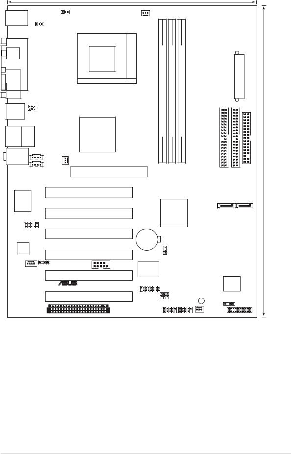
1.5Motherboard layout
|
|
|
24.5cm (9.6in) |
|
|
|
|
|
|
|
PS/2KBMS |
OVER_VOLT1 |
|
|
|
|
|
|
|
|
|
T: Mouse |
CPU_FAN |
|
|
|
|
|
|
|
||
|
|
|
|
|
|
|
|
|||
B: Keyboard |
|
|
|
|
|
|
|
|
|
|
|
KBPWR |
Socket462 |
module)pin-bit,184(64/72 |
module)pin-bit,184(64/72 |
module)pin-bit,184(64/72 |
|
ConnectorPowerATX |
|
|
|
SPDIF_O |
PORTPARALLEL |
|
|
|
|
|||||
COM1 |
|
|
|
|
|
|
|
|
|
|
USB1 |
|
USBPW12 |
|
DIMM1 |
DIMM2 |
DIMM3 |
|
|
|
|
|
USBPW34 |
|
|
|
|
|
||||
USB2 |
|
|
|
|
|
|
|
|||
|
|
|
|
|
|
|
|
|
|
|
|
|
|
VIA |
DDR |
DDR |
DDR |
|
|
|
|
USB2.0 Top: |
|
KT600 |
|
|
|
|
||||
T: USB4 |
RJ-45 |
|
|
|
|
|
|
|
|
|
B: USB3 |
|
|
Chipset |
|
|
|
|
|
|
(12.0in) |
|
|
|
|
|
|
|
|
|
||
Top:Line In |
|
|
|
|
|
|
|
|
||
Center:Line Out |
AUX |
|
|
|
|
|
|
|
|
|
Below:Mic In |
|
|
|
|
|
|
|
|
||
PWR_FAN |
|
|
|
|
|
|
30.5cm |
|||
|
|
|
|
|
IDEPRI |
IDESEC |
FLOPPY |
|||
|
|
CD |
|
|
|
|
||||
|
|
|
|
|
|
|
|
|
|
|
|
|
Accelerated Graphics Port (AGP) |
|
|
|
|
|
|
|
|
Marvell |
Gigabit LAN |
|
PCI1 |
|
VIA |
|
|
|
|
|
|
A7V600 SE |
|
SATA2 |
SATA1 |
|
|||||
|
|
|
PCI2 |
|
VT8237 |
|
|
|
|
|
|
|
|
|
South |
|
|
|
|
||
FP_AUDIO |
|
Bridge |
|
|
|
|
|
PCI3 |
|
CR2032 3V |
|
|
|
Lithium Cell |
|
|
|
CMOS Power |
|
AD1980 |
|
|
|
CODEC |
|
|
|
PCI4 |
|
CLRTC |
|
SPDIF_OUT2 |
|
Super |
|
MODEM |
COM2 |
|
|
PCI5 |
|
I/O |
|
|
|
4Mbit |
|
|
|
|
|
® |
|
GAME |
Low Pin |
|
|
||
|
|
Count |
|
|
|
|
|
PCI6 |
|
USBPW78 |
SB_PWR |
|
USBPW56 |
||
|
|
|
|
|
|
|
CHASSIS |
|
WIFI |
USB56 USB78 |
CHA_FAN |
|
PANEL |
||
|
|
ASUS A7V600 SE Motherboard |
1-9 |
1.6Before you proceed
Take note of the following precautions before you install motherboard components or change any motherboard settings.
1.Unplug the power cord from the wall socket before touching any component.
2.Use a grounded wrist strap or touch a safely grounded object or to a metal object, such as the power supply case, before handling components to avoid damaging them due to static electricity.
3.Hold components by the edges to avoid touching the ICs on them.
4.Whenever you uninstall any component, place it on a grounded antistatic pad or in the bag that came with the component.
5.Before you install or remove any component, ensure that the ATX power supply is switched off or the power cord is detached from the power supply. Failure to do so may cause severe damage to the motherboard, peripherals, and/or components.
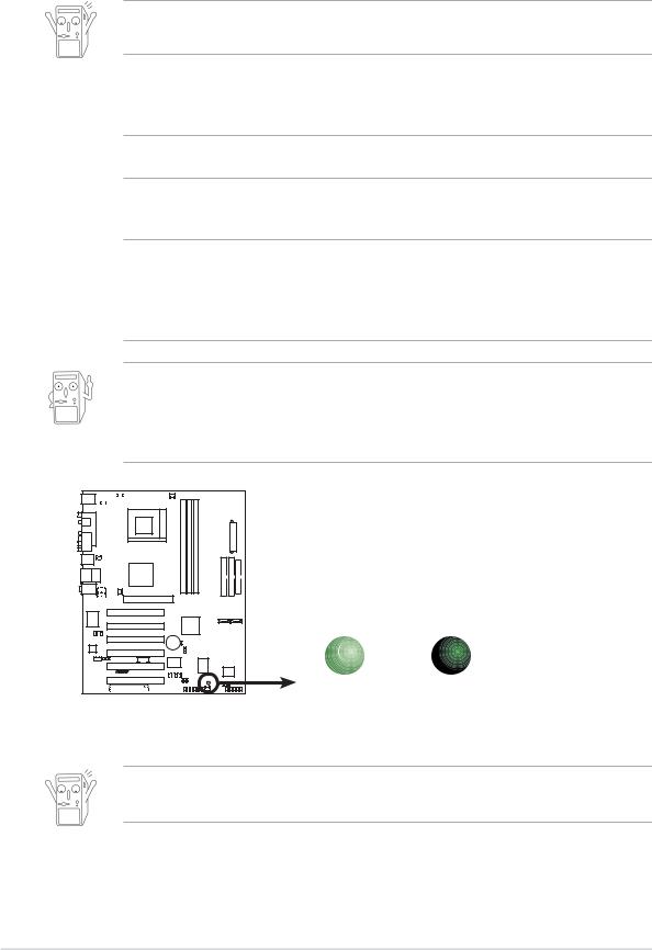
When lit, the green LED (SB_PWR) indicates that the system is ON, in sleep mode, or in soft-off mode, a reminder that you should shut down the system and unplug the power cable before removing or plugging in any motherboard component.
A7V600 SE |
SB_PWR
ON |
OFF |
A7V600 SE Onboard LED |
Standby |
Powered |
Power |
Off |
Install only 1.5V AGP cards on this motherboard to prevent damage to your AGP card or motherboard.
1-10 |
Chapter 1: Motherboard Information |
1.7Motherboard installation
Before you install the motherboard, study the configuration of your chassis to ensure that the motherboard fits into it. The motherboard uses the ATX form factor that measures 12 inches x 9.6 inches (30.5 cm x 24.5 cm).
Make sure to unplug the power cord before installing or removing the motherboard. Failure to do so may cause you physical injury and damage motherboard components.
1.7.1 Placement direction
When installing the motherboard, make sure that you place it into the chassis in the correct orientation. The edge with external ports goes to the rear part of the chassis as indicated in the image below.
1.7.2 Screw holes
Place nine (9) screws into the holes indicated by circles to secure the motherboard to the chassis.
Do not overtighten the screws! Doing so may damage the motherboard.
Place this side towards the rear of the chassis
ASUS A7V600 SE Motherboard |
1-11 |
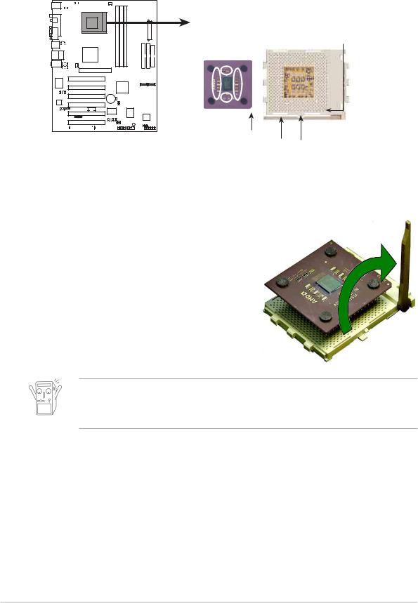
1.8Central Processing Unit (CPU)
The motherboard provides a Socket A (462) for CPU installation. AMD processors offer gigahertz speeds to support all the latest computing platforms and applications. The A7V600 SE supports AthlonTM XP, AthlonTM, Barton™ and Duron TM processors.
CPU NOTCH
TO INNER
CORNER
AMD™ CPU
A7V600 SE |
A7V600 SE Socket A
CPU NOTCH
LEVER LOCK
Installing the CPU
Follow these steps to install a CPU:
1.Locate the Socket 462 and open it by pulling the lever gently sideways away from the socket. Then lift the lever upwards. The socket lever must be fully opened (90 to 100 degrees).
2.Insert the CPU with the correct orientation. The notched or golden corner of the CPU must be oriented toward the inner corner of the socket base nearest to the lever hinge.
The CPU should drop easily into place. Do not force the CPU into the socket to avoid bending the pins. If the CPU does not fit, check its alignment and look for bent pins.
4.Once completely inserted, press the CPU firmly and close the socket lever until it snaps shut.
5.Place the CPU fan and heatsink on the CPU. The heatsink should entirely cover the CPU. Carefully attach the heatsink locking brace to the plastic clips on the socket base. With the added weight of the CPU fan and heatsink locking brace, no extra force is required to keep the CPU in place
1-12 |
Chapter 1: Motherboard Information |
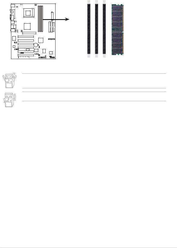
1.9System memory
The motherboard has three Double Data Rate (DDR) DIMM sockets that supports up to 3GB unbuffered non-ECC PC3200/2700/2100 DDR DIMMs.
A DDR DIMM has the same physical dimensions as an SDR DIMM, but it has a 184-pin footprint compared to the 168-pin of the SDR DIMM. Also, a DDR DIMM is single notched while an SDR DIMM is double notched.
A7V600 SE |
DIMM1 |
DIMM2 |
DIMM3 |
|
|
|
Pins |
|
|
|
|
|||||
|
|
|
|
|
104 |
||
|
|
|
|
|
|
|
80 Pins |
|
|
|
|
|
|
|
|
|
|
|
|
|
|
|
|
|
|
|
|
|
|
||
|
|
|
|
|
|
|
|
A7V600 SE 184-Pin DDR DIMM Sockets
A DDR DIMM is keyed with a notch so that it fits in only one direction. DO NOT force a DIMM into a socket to avoid damaging the DIMM.
PC3200 maximum to 2 banks only.
DDR400 Qualified Vendor List
The following table lists the PC3200-DDR400 memory modules that have been tested and qualified for use with this motherboard. Make sure to use only the tested and qualified DDR400 DIMMs listed below. Visit the ASUS website (www.asus.com) for the latest DDR Qualified Vendors List.
Size |
Vendor |
Part Number |
Brand |
SS/ |
Chip Number |
A* |
B* |
DS |
|||||||
|
|
|
|
|
|
|
|
|
|
|
|
|
|
|
|
256MB |
TwinMos |
M2G9I08AFATT9F081AA4T |
TwinMos |
SS |
TMD7608F8E50D |
• |
• |
|
|
|
|
|
|
|
|
512MB |
TwinMos |
M2G9J16AGATT9F081AA4T |
TwinMos |
DS |
TMD7608F8E50D |
|
• |
|
|
|
|
|
|
|
|
256MB |
Apacer |
77.10636.465 |
Samsung |
SS |
K4H560838D-TCC4 |
• |
|
|
|
|
|
|
|
|
|
256MB |
Transcend |
TS32MLD64V4F3 |
Samsung |
SS |
K4H560838D-TCCC |
• |
|
|
|
|
|
|
|
|
|
256MB |
ADATA |
MDOAD5F3G315B1EC2 |
ADATA |
SS |
ADD8608A8A-5B |
• |
• |
|
|
|
|
|
|
|
|
256MB |
ADATA |
MDOSS6F3G31JB1EAE |
Samsung |
SS |
K4H560838D-TCC4 |
• |
• |
|
|
|
|
|
|
|
|
256MB |
ADATA |
MDOWB5F3G316B1EAE |
Winbond |
SS |
W942508BH-5 |
• |
• |
|
|
|
|
|
|
|
|
256MB |
GEIL |
MAG32UL6464D2TG5A-KC |
GEIL |
SS |
GL3LC32G88TG-5A |
• |
• |
|
|
|
|
|
|
|
|
(Continued on the next page)
ASUS A7V600 SE Motherboard |
1-13 |

DDR400 Qualified Vendor List
Size |
Vendor |
Part Number |
Brand |
SS/ |
Chip Number |
A* |
B* |
DS |
|||||||
|
|
|
|
|
|
|
|
256MB |
Kingston |
KVR400X64C25/256 |
Winbond |
SS |
W942508BH-5 |
• |
• |
|
|
|
|
|
|
|
|
256MB |
Kingston |
KVR400X64C3A/256 |
Hynix |
SS |
HY5DU56822BT-D43 |
• |
|
|
|
|
|
|
|
|
|
512MB |
Kingston |
KVR400X64C3A/512 |
Hynix |
DS |
HY5DU56822BT-D43 |
• |
|
|
|
|
|
|
|
|
|
256MB |
Winbond |
W9425GCDB-5 |
Winbond |
SS |
W942508CH-5 |
• |
• |
|
|
|
|
|
|
|
|
128MB |
Infineon |
HYS64D16301GU-5-B |
Hynix |
SS |
HYB25D256160BT-5B |
• |
• |
|
|
|
|
|
|
|
|
256MB |
Infineon |
HYS64D32300GU-5-B |
Hynix |
SS |
HYB25D256800BT-5B |
• |
• |
|
|
|
|
|
|
|
|
512MB |
Infineon |
HYS64D32300GU-5-B |
Hynix |
DS |
HYB25D256800BT-5B |
• |
• |
|
|
|
|
|
|
|
|
256MB |
Samsung |
M368L3223ETM-CCC |
Samsung |
SS |
K4H560838E-TCCC |
• |
• |
|
|
|
|
|
|
|
|
512MB |
Samsung |
M368L6423ETM-CCC |
Samsung |
DS |
K4H560838E-TCCC |
• |
• |
|
|
|
|
|
|
|
|
256MB |
Hynix |
HYMD232646B8J-D43 AA |
Hynix |
SS |
HY5DU56822BT-D43 |
• |
• |
|
|
|
|
|
|
|
|
512MB |
Hynix |
HYMD264646B8J-D43 AA |
Hynix |
DS |
HY5DU56822BT-D43 |
• |
• |
|
|
|
|
|
|
|
|
512MB |
PSC |
AL6D8A53T1-5B |
PSC |
DS |
A2S56D30ATP |
• |
• |
|
|
|
|
|
|
|
|
256MB |
TwinMos |
M2S9I08AFAPS9F0811A-T |
PSC |
SS |
A2S56D30ATP |
• |
• |
|
|
|
|
|
|
|
|
512MB |
KINGMAX |
MPXB62D-68KX3 |
Kingmax |
DS |
KDL684T4AA-50 |
• |
• |
|
|
|
|
|
|
|
|
512MB |
Micron |
MT16VDDT6464AG-40BC4 |
Micron |
DS |
MT46V32M8TG-5BC |
• |
• |
|
|
|
|
|
|
|
|
256MB |
ATP |
AG32L64T8SQC4S |
Samsung |
SS |
K4H560838D-TCC4 |
• |
|
|
|
|
|
|
|
|
|
128MB |
NANYA |
NT128D64SH4B1G-5T |
NANYA |
SS |
NT5DS16M16BT-5T |
• |
• |
|
|
|
|
|
|
|
|
256MB |
NANYA |
NT256D64S88B1G-5T |
NANYA |
SS |
NT5DS32M8BT-5T |
• |
• |
|
|
|
|
|
|
|
|
512MB |
NANYA |
N512D64S8HB1G-5T |
NANYA |
DS |
NT5DS32M8BT-5T |
• |
• |
|
|
|
|
|
|
|
|
256MB |
TwinMos |
M2G9I08AFTT9F0811DDT |
TwinMos |
SS |
TMD7608F8E50B |
• |
|
|
|
|
|
|
|
|
|
512MB |
ATP |
AG28L64T8SMC4M |
Samsung |
DS |
MT46V64M4TG-5BC |
• |
|
|
|
|
|
|
|
|
|
256MB |
Brain Power |
B6U808-256M-SAM-400 |
Samsung |
SS |
K4H560838D-TCC4 |
• |
|
|
|
|
|
|
|
|
|
512MB |
Brain Power |
B6U808-512M-SAM-400 |
Samsung |
DS |
K4H560838D-TCC4 |
• |
|
|
|
|
|
|
|
|
|
512MB |
Transcend |
TS64MLD64V4F3 |
Mosel |
DS |
HY5DU56822BT-D43 |
• |
|
|
|
|
|
|
|
|
|
256MB |
Century |
DXV6S8SSCCD3K27C |
Samsung |
SS |
K4H560838D-TCCC |
• |
|
|
|
|
|
|
|
|
|
512MB |
Century |
DXV6S8SSCCD3K27C |
Samsung |
DS |
K4H560838D-TCC4 |
• |
• |
|
|
|
|
|
|
|
|
256MB |
Elixir |
M2U25664DS88B3G-5T |
Elixir |
SS |
N2DS25680BT-5T |
• |
• |
|
|
|
|
|
|
|
|
512MB |
Elixir |
M2U25664DS8HB3G-5T |
Elixir |
DS |
N2DS25680BT-5T |
• |
• |
|
|
|
|
|
|
|
|
Legend:
A* - Supports one module inserted into any slot.
B* - Supports one pair of module inserted into any two slots.
1-14 |
Chapter 1: Motherboard Information |

1.10 Expansion slots
The A7V600 SE motherboard has six (6) expansion PCI slots and one (1) AGP 8X slot. The following sub-sections describe the slots and the expansion cards that they support.
1.10.1 Configuring an expansion card
After physically installing the expansion card, configure the card by adjusting the software settings.
1.Turn on the system and change the necessary BIOS settings, if any.
2.Assign an IRQ to the card. Refer to the tables below.
3.Install the software drivers for the expansion card.
1.10.2 |
Standard Interrupt Assignments |
|
IRQ |
Priority |
Standard Function |
0 |
1 |
System Timer |
1 |
2 |
Keyboard Controller |
2 |
N/A |
Programmable Interrupt |
3* |
11 |
Communications Port (COM2) |
4* |
12 |
Communications Port (COM1) |
5* |
13 |
Sound Card (sometimes LPT2) |
6 |
14 |
Floppy Disk Controller |
7* |
15 |
Printer Port (LPT1) |
8 |
3 |
System CMOS/Real Time Clock |
9* |
4 |
ACPI Mode when used |
10* |
5 |
IRQ Holder for PCI Steering |
11* |
6 |
IRQ Holder for PCI Steering |
12* |
7 |
PS/2 Compatible Mouse Port |
13 |
8 |
Numeric Data Processor |
14* |
9 |
Primary IDE Channel |
15* |
10 |
Secondary IDE Channel |
*These IRQs are usually available for ISA or PCI devices.
ASUS A7V600 SE Motherboard |
1-15 |
IRQ assignments for this motherboard
|
A |
B |
C |
D |
E |
|
F |
G |
H |
PCI slot 1 |
— |
— |
— |
shared |
— |
— |
— |
— |
|
PCI slot 2 |
shared |
— |
— |
— |
— |
— |
— |
— |
|
PCI slot 3 |
— |
shared |
— |
— |
— |
— |
— |
— |
|
PCI slot 4 |
— |
— |
shared |
— |
— |
— |
— |
— |
|
PCI slot 5 |
— |
— |
— |
shared |
— |
— |
— |
— |
|
PCI slot 6 |
shared |
— |
— |
— |
— |
— |
— |
— |
|
AGP slot |
shared |
— |
— |
— |
— |
— |
— |
— |
|
USB 1.1 UHCI 1 |
— |
— |
— |
— |
shared |
— |
— |
— |
|
USB 1.1 UHCI 2 |
— |
— |
— |
— |
shared |
— |
— |
— |
|
USB 1.1 UHCI 3 |
— |
— |
— |
— |
— |
shared |
— |
— |
|
USB 1.1 UHCI 4 |
— |
— |
— |
— |
— |
shared |
— |
— |
|
USB 2.0 EHCI |
— |
— |
— |
— |
— |
— |
shared |
— |
|
USB Device |
— |
— |
— |
— |
— |
— |
— |
shared |
|
AC97 Codec |
— |
— |
— |
— |
— |
— |
shared |
— |
|
Onboard LAN |
— |
— |
shared |
— |
— |
— |
— |
— |
|
Onboard SATA |
— |
— |
— |
— |
shared |
— |
— |
— |
|
Onboard IDE |
— |
— |
— |
— |
shared |
— |
— |
— |
|
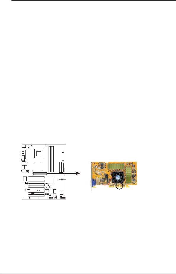
1.10.3 AGP slot
This motherboard has an Accelerated Graphics Port (AGP) slot that supports +1.5V AGP cards only. When you buy an AGP card, make sure that you ask for one with +1.5V specification. Note the notches on the card golden fingers to ensure that they fit the AGP slot on your motherboard.
A7V600 SE
Keyed for 1.5v
A7V600 SE Accelerated Graphics Port (AGP)
1-16 |
Chapter 1: Motherboard Information |
 Loading...