


 ® A7V266-E
JumperFree™ DDR DRAM
266MHz FSB AGP Pro/4X
Socket A Motherboard
USER’S MANUAL

USER'S NOTICE
No part of this manual, including the products and software described in it, may be reproduced, transmitted, transcribed, stored in a retrieval system, or translated into any language in any form or by any means, except documentation kept by the purchaser for backup purposes, without the express written permission of ASUSTeK COMPUTER INC. (“ASUS”).
ASUS PROVIDES THIS MANUAL “AS IS” WITHOUT WARRANTY OF ANY KIND, EITHER EXPRESS OR IMPLIED, INCLUDING BUT NOT LIMITED TO THE IMPLIED WARRANTIES OR CONDITIONS OF MERCHANTABILITY OR FITNESS FOR A PARTICULAR PURPOSE. IN NO EVENT SHALLASUS, ITS DIRECTORS, OFFICERS, EMPLOYEES OR AGENTS BE LIABLE FOR ANY INDIRECT, SPECIAL, INCIDENTAL, OR CONSEQUENTIAL DAMAGES (INCLUDING DAMAGES FOR LOSS OF PROFITS, LOSS OF BUSINESS, LOSS OF USE OR DATA, INTERRUPTION OF BUSINESS AND THE LIKE), EVEN IF ASUS HAS BEEN ADVISED OF THE POSSIBILITY OF SUCH DAMAGES ARISING FROM ANY DEFECT OR ERROR IN THIS MANUAL OR PRODUCT.
Product warranty or service will not be extended if: (1) the product is repaired, modified or altered, unless such repair, modification of alteration is authorized in writing by ASUS; or (2) the serial number of the product is defaced or missing.
Products and corporate names appearing in this manual may or may not be registered trademarks or copyrights of their respective companies, and are used only for identification or explanation and to the owners’ benefit, without intent to infringe.
•Intel and Pentium are registered trademarks of Intel Corporation.
•VIA is a registered trademark of VIA Technologies, Inc.
•3Com is a registered trademark of 3Com Corporation.
•C-Media is a registered trademark of C-Media Electronics Inc.
•Windows and MS-DOS are registered trademarks of Microsoft Corporation.
•Adobe and Acrobat are registered trademarks of Adobe Systems Incorporated.
•Trend and ChipAwayVirus are trademarks of Trend Micro, Inc.
•Symbios is a registered trademark of Symbios Logic Corporation.
The product name and revision number are both printed on the product itself. Manual revisions are released for each product design represented by the digit before and after the period of the manual revision number. Manual updates are represented by the third digit in the manual revision number.
For previous or updated manuals, BIOS, drivers, or product release information, contact ASUS at http://www.asus.com.tw or through any of the means indicated on the following page.
SPECIFICATIONS AND INFORMATION CONTAINED IN THIS MANUAL ARE FURNISHED FOR INFORMATIONAL USE ONLY, AND ARE SUBJECT TO CHANGE AT ANY TIME WITHOUT NOTICE, AND SHOULD NOT BE CONSTRUED AS A COMMITMENT BY ASUS. ASUS ASSUMES NO RESPONSIBILITY OR LIABILITY FOR ANY ERRORS OR INACCURACIES THAT MAY APPEAR IN THIS MANUAL, INCLUDING THE PRODUCTS AND SOFTWARE DESCRIBED IN IT.
Copyright © 2001 ASUSTeK COMPUTER INC. All Rights Reserved.
Product Name: |
ASUS A7V266-E |
Manual Revision: |
1.00 E883 |
Release Date: |
October 2001 |
|
|
2 |
ASUS A7V266-E User’s Manual |

ASUS CONTACT INFORMATION
ASUSTeK COMPUTER INC. (Asia-Pacific)
Marketing
Address: |
150 Li-Te Road, Peitou, Taipei, Taiwan 112 |
Telephone: |
+886-2-2894-3447 |
Fax: |
+886-2-2894-3449 |
Email: |
info@asus.com.tw |
Technical Support
MB/Others (Tel): |
+886-2-2890-7121 (English) |
|
Notebook (Tel): |
+886-2-2890-7122 |
(English) |
Desktop/Server (Tel):+886-2-2890-7123 |
(English) |
|
Fax: |
+886-2-2890-7698 |
|
Email: |
tsd@asus.com.tw |
|
WWW: |
www.asus.com.tw |
|
FTP: |
ftp.asus.com.tw/pub/ASUS |
|
ASUS COMPUTER INTERNATIONAL (America)
Marketing
Address: |
6737 Mowry Avenue, Mowry Business Center, Building 2 |
|
Newark, CA 94560, USA |
Fax: |
+1-510-608-4555 |
Email: |
tmd1@asus.com |
Technical Support
Fax: |
+1-510-608-4555 |
Email: |
tsd@asus.com |
WWW: |
www.asus.com |
FTP: |
ftp.asus.com/Pub/ASUS |
ASUS COMPUTER GmbH (Europe)
Marketing
Address: |
Harkortstr. 25, 40880 Ratingen, BRD, Germany |
Fax: |
+49-2102-442066 |
Email: |
sales@asuscom.de (for marketing requests only) |
Technical Support
Hotline: |
MB/Others: +49-2102-9599-0 Notebook: +49-2102-9599-10 |
Fax: |
+49-2102-9599-11 |
Support (Email): |
www.asuscom.de/de/support (for online support) |
WWW: |
www.asuscom.de |
FTP: |
ftp.asuscom.de/pub/ASUSCOM |
ASUS A7V266-E User’s Manual |
3 |

CONTENTS
1. INTRODUCTION ............................................................................. |
7 |
|
1.1 |
How This Manual Is Organized ................................................... |
7 |
1.2 |
Item Checklist .............................................................................. |
7 |
2. FEATURES ........................................................................................ |
8 |
|
2.1 |
ASUS A7V266-E Motherboard ................................................... |
8 |
|
2.1.1 Specifications ..................................................................... |
8 |
|
2.1.2 Performance ...................................................................... |
10 |
|
2.1.3 Intelligence ....................................................................... |
11 |
2.2 |
Motherboard Components .......................................................... |
12 |
|
2.2.1 Component Locations ....................................................... |
13 |
3. HARDWARE SETUP ...................................................................... |
14 |
|
3.1 |
Motherboard Layout .................................................................. |
14 |
3.2 |
Layout Contents ......................................................................... |
15 |
3.3 |
Hardware Setup Procedure ......................................................... |
17 |
3.4 |
Motherboard Settings ................................................................. |
17 |
3.5 |
System Memory ......................................................................... |
25 |
|
3.5.1 DDR DIMM Support ........................................................ |
25 |
|
3.5.1 General DIMM Notes ....................................................... |
26 |
|
3.5.2 Memory Installation ......................................................... |
26 |
3.6 |
Central Processing Unit (CPU) .................................................. |
27 |
3.7 |
Expansion Cards ........................................................................ |
28 |
|
3.7.1 Installing an Expansion Card ........................................... |
28 |
|
3.7.2 Assigning IRQs for Expansion Cards .............................. |
29 |
|
3.7.3 Accelerated Graphics Port (AGP) Pro Slot ...................... |
30 |
|
3.7.4 Advanced Communication Riser (ACR) Slot .................. |
30 |
3.8 |
Connectors ................................................................................ |
31 |
|
3.8.1 External Connectors ......................................................... |
31 |
3.9 |
Starting Up the First Time .......................................................... |
44 |
4. BIOS SETUP ..................................................................................... |
45 |
|
4.1 |
Managing and Updating Your BIOS .......................................... |
45 |
|
4.1.1 Upon First Use of the Computer System .......................... |
45 |
|
4.1.2 Updating BIOS Procedures .............................................. |
47 |
4.2 |
BIOS Setup Program .................................................................. |
49 |
|
4.2.1 BIOS Menu Bar ................................................................ |
50 |
|
4.2.2 Legend Bar ....................................................................... |
50 |
4 |
ASUS A7V266-E User’s Manual |

|
CONTENTS |
|
4.3 |
Main Menu ................................................................................. |
52 |
|
4.3.1 Primary & Secondary Master/Slave ................................. |
53 |
|
4.3.2 Keyboard Features ............................................................ |
56 |
4.4 |
Advanced Menu ......................................................................... |
58 |
|
4.4.1 Chip Configuration ........................................................... |
62 |
|
4.4.2 I/O Device Configuration ................................................. |
65 |
|
4.4.3 PCI Configuration ............................................................ |
67 |
4.5 |
Power Menu ............................................................................... |
69 |
|
4.5.1 Power Up Control ............................................................. |
71 |
|
4.5.2 Hardware Monitor ............................................................ |
73 |
4.6 |
Boot Menu ................................................................................. |
74 |
4.7 |
Exit Menu ................................................................................... |
76 |
5. SOFTWARE SETUP ....................................................................... |
79 |
|
5.1 |
Install Operating System ............................................................ |
79 |
5.2 |
Start Windows ............................................................................ |
79 |
5.3 |
A7V266-E Motherboard Support CD ........................................ |
80 |
|
5.3.1 Installation Menu .............................................................. |
80 |
5.4 |
Using the Promise Chip for RAID 0 or 1 ................................... |
82 |
6. SOFTWARE REFFERENCE ......................................................... |
91 |
|
6.1 |
Winbond Smart Manager ........................................................... |
91 |
6.2 |
ASUS PC Probe ......................................................................... |
95 |
6.3 |
Multi-Channel Audio Feature Setup ......................................... |
100 |
6.4 |
ASUS Live Update ................................................................... |
102 |
6.5 |
3Deep Color Tuner ................................................................... |
103 |
6.6 |
CyberLink PowerPlayer SE ..................................................... |
105 |
6.7 |
CyberLink VideoLive Mail ...................................................... |
106 |
7. APPENDIX ..................................................................................... |
109 |
|
7.1 |
Modem Riser ............................................................................ |
109 |
|
7.1.1 56K Software Modem .................................................... |
109 |
|
7.1.2 Primary/Seconday MR ................................................... |
109 |
|
7.1.3 Hardware Installation Procedure .................................... |
109 |
|
7.1.4 Software Setup in Windows 98 ...................................... |
110 |
7.2 |
Glossary ................................................................................... |
111 |
INDEX ................................................................................................. |
115 |
|
ASUS A7V266-E User’s Manual |
5 |

FCC & DOC COMPLIANCE
Federal Communications Commission Statement
This device complies with FCC Rules Part 15. Operation is subject to the following two conditions:
•This device may not cause harmful interference, and
•This device must accept any interference received, including interference that may cause undesired operation.
This equipment has been tested and found to comply with the limits for a Class B digital device, pursuant to Part 15 of the FCC Rules. These limits are designed to provide reasonable protection against harmful interference in a residential installation. This equipment generates, uses and can radiate radio frequency energy and, if not installed and used in accordance with manufacturer's instructions, may cause harmful interference to radio communications. However, there is no guarantee that interference will not occur in a particular installation. If this equipment does cause harmful interference to radio or television reception, which can be determined by turning the equipment off and on, the user is encouraged to try to correct the interference by one or more of the following measures:
•Re-orient or relocate the receiving antenna.
•Increase the separation between the equipment and receiver.
•Connect the equipment to an outlet on a circuit different from that to which the receiver is connected.
•Consult the dealer or an experienced radio/TV technician for help.
WARNING!Any changes or modifications to this product not expressly approved by the manufacturer could void any assurances of safety or performance and could result in violation of Part 15 of the FCC Rules.
Reprinted from the Code of Federal Regulations #47, part 15.193, 1993. Washington DC: Office of the Federal Register, National Archives and Records Administration, U.S. Government Printing Office.
Canadian Department of Communications Statement
This digital apparatus does not exceed the Class B limits for radio noise emissions from digital apparatus set out in the Radio Interference Regulations of the Canadian Department of Communications.
This Class B digital apparatus complies with Canadian ICES-003.
Cet appareil numérique de la classe B est conforme à la norme NMB-003 du Canada.
6 |
ASUS A7V266-E User’s Manual |

1.INTRODUCTION
1.1How This Manual Is Organized
This manual is divided into the following sections:
1. |
INTRODUCTION |
Manual information and checklist |
2. |
FEATURES |
Production information and specifications |
3. |
HARDWARE SETUP |
Instructions on setting up the motherboard. |
4. |
BIOS SETUP |
Instructions on setting up the BIOS |
5. |
SOFTWARE SETUP |
Instructions on setting up the included software |
6. |
SOFTWARE REFERENCE |
Reference material for the included software |
7. |
APPENDIX |
Optional items and general reference |
1.2 Item Checklist
Check that your package is complete. If you discover damaged or missing items,
contact your retailer.
Package Contents
(1) ASUS Motherboard
(1) 40-pin 80-conductor ribbon cable for internal UltraDMA100/66//33 IDE drives
(1)Ribbon cable for two 3.5” floppy disk drives
(1) ASUS Support CD with drivers and utilities
(1) Bag of spare jumper caps
(1) ASUS 2-port USB Connector
Set
(1) User’s Manual
Optional Items
ASUS IrDA-compliant infrared module
Manual / Checklist
1. INTRODUCTION
ASUS A7V266-E User’s Manual |
7 |

Specifications |
2.FEATURES |
|
|
2.FEATURES
2.1ASUS A7V266-E Motherboard
The ASUS A7V266-E motherboard is the perfect answer for home PCs, workstations and servers. The A7V266-E is powered by the AMD® Athlon™ /Duron™ processor and is bundled with advanced features to provide superlative performance.
2.1.1 Specifications
• AMD® Athlon™ / Athlon XP™ and Duron™ Processor Support
•North Bridge System Chipset: Features the VIA® KT266A North Bridge that supports AGP 4X/2X mode, 133/100MHz Front Side Bus (FSB), and 266/200MHz memory bus.
•South Bridge System Chipset: VIA® VT8233 integrated peripheral controller supports UltraDMA/100/66/33 for burst mode data transfer rates of up to 100MB/ sec, and USB controller with three root hubs for six USB ports.
•PC2100 / PC1600 DDR Support: Equipped with three Double Data Rate Dual Inline Memory Module (DDR DIMM) sockets to support up to 3GB of DDR DRAM. DDR DRAM is the newest memory standard with the highest bandwidth and lowest latency currently available and dramatically improves the memory system’s ability to service, among others, high multimedia requirements. (Caution: Do not attempt to use SDRAM modules.)
• JumperFree™ Mode: Allows processor settings and easy overclocking of frequency and Vcore voltage through BIOS. Easy-to-use DIP switches come with the motherboard board to allow manual adjustment of the processor external/ internal frequency.
•UltraDMA/100 Support: Comes with an onboard PCI Bus Master IDE controller with two connectors that support four IDE devices on two channels. Supports UltraDMA/100, UltraDMA/66, UltraDMA/33, PIO Modes 3 & 4, Bus Master IDE DMA Mode 2, and Enhanced IDE devices, such as DVD-ROM, CD-ROM, CD-R/RW, LS-120, and Tape Backup drives.
•Super Multi-I/O: The multi-I/O chipset offers complete support for a variety of I/O functions. Provides two high-speed UART compatible serial ports and one parallel port with EPP and ECP capabilities. UART2 can also be directed from COM2 to the Infrared Module for wireless connections. The Super I/O controller also supports a floppy disk drive, PS/2 keyboard, and PS/2 mouse.
•Promise® chip: The Promise IDE controller chip supports the ATA-100 protocol and Ultra DMA/100 data transfer speeds. The chip also delivers reliable redundancy and stable performance for RAID levels 0 or 1. Data “striping,” or RAID 0, improves speed performance as I/O tasks are spread between two hard disk drives. Data “mirroring,” or RAID 1, improves system fault tolerance as the protocol optimizes two identical hard disks to write data to each other.
8 |
ASUS A7V266-E User’s Manual |

2.FEATURES
•Smart BIOS: 2Mb firmware enables Vcore and CPU/DDR SDRAM frequency adjustments, boot block write protection, and HD/SCSI/MO/ZIP/CD/Floppy boot selection.
2.1.2 Connections
•CPU socket: Socket A (462) for AMD® processors.
•PCI Expansion Slots: Provides five 32-bit Legacy Free PCI slots, (PCI 2.2 compliant) with no ISA, eliminating bottlenecks and system memory management issues. All PCI slots can support Bus Master PCI cards, such as SCSI or LAN cards. (PCI supports up to 133MB/s maximum throughput.) The MB supports Concurrent PCI, which allows multiple PCI transfers from PCI master bus to the memory and processor.
•IDE connectors: Dual-channel bus master IDE connectors support up to four Ultra DMA/100/66, PIO Modes 3 & 4 IDE devices like two HDDs, one DVD and an R/W CD.
•AGP Pro Slot: Comes with an Accelerated Graphics Port Pro slot that supports AGP cards for high performance, component level interconnect targeted at 3D graphical applications using a 4X mode bus. The slot is keyed to support only the latest 1.5 volt AGP cards.
•Floppy disk connector: Supports the floppy disk drive.
•Wake-On-LAN: Supports Wake-On-LAN activity through an optional ASUS PCI-L101 10 /100 Fast Ethernet PCI card.
•Wake-On-Ring: Supports Wake-On-Ring activity through a PCI modem card.
•Smartcard Reader Connector: Supports a PS/SC compatible Smart Card
•USB ports: Four Universal Serial Bus (USB) ports are available for connecting USB devices such as a mouse and PDA.
•Serial ports: Two 9-pin COM1/COM2 ports are for all serial devices.
•IrDA: Supports an optional infrared port module for a wireless interface.
•Microphone: Pink jack connects a microphone (or 6 channel speaker).
•Line In: Light blue jack connects a tape player (or 6 channel speaker).
•Line Out: Lime jack connects a headphone, a speaker (or 6 channel speaker).
•Game/MIDI connector. This connector supports a joystick or a game pad for playing games, and MIDI devices for playing or editing audio files.
•Parallel port: 25-pin port connects a parallel printer or other devices.
•PS/2 mouse port: Green 6-pin connector is for a PS/2 mouse.
•PS/2 keyboard port: Purple 6-pin connector is for a PS/2 keyboard.
•Onboard LED: Signals AC power is okay.
•ATX power connector. Supplies the MB with ATX 12V power. The power supply must have at least 1A on the +5V standby lead (+5VSB).
2.FEATURES |
Specifications |
|
|
ASUS A7V266-E User’s Manual |
9 |

Performance |
2.FEATURES |
|
|
2.FEATURES
2.1.2Performance
•DDR DRAM Optimized Performance: This motherboard supports a new generation memory, Double Data Rate (DDR) Dynamic Random Access Memory (DDR DRAM). This new memory technology increases performance by executing two actions per clock cycle, resulting in data transfer rates of up to 2.1 GB/s for 133MHz DDR SDRAM and 1.6GB/s for 100MHz DDR SDRAM.
•Onboard Audio: Audio models come with the six-channel C-Media CMI8738 PCI audio controller that supplies HRTF 3D positional audio functions. The chip supports software access to PC DVD 5.1/6.1 and AC-3/DTS via SPDIF.
Other integrative featues include: full DVD playback, PCtel 56K modem, and even Karaoke echo effects. The chip offers 24-bit SPDIF digital recording and playback with additional support for legacy audio SBPRO™ and FM emulator/ DLS wavetable music synthesis. A software package helps setup the multichannel PC sound system.
•ACPI Ready: Advanced Configuration Power Interface (ACPI) provides more Energy Saving Features for operating systems that support OS Direct Power Management (OSPM) functionality. With these features employed in the OS, PCs can be ready around the clock but comply with energy saving standards. To fully utilize the ACPI benefits, use an ACPI-supported OS such as Windows 98.
•Smartcard Reader Connector: This connector that provides the convenience of PS/SC compatible Smart Card security plus support for a multitude of new financial, telephonic, and mobile access services.
•PC’99 Compliant: Both the BIOS and hardware levels of ASUS smart series motherboards are PC’99 compliant. The new PC’99 requirements for systems and components are based on the following high-level goals: Support for Plug- n-Play compatibility and power management for configuring and managing all system components, and 32-bit device drivers and installation procedures for Windows95/98/NT . Color-coded connectors and descriptive icons make identification easy as required by PC’99.
•High-Speed Data Transfer Interface: Support for UltraDMA/100 through the onboard IDE bus master controller triples the UltraDMA/33 burst transfer rate. UltraDMA/100 is backward compatible with DMA/66, DMA/33, and other existing DMA devices to save the need to upgrade current EIDE/IDE drives. (UltraDMA/66 requires a 40-pin 80-conductor cable).
•Concurrent PCI: Concurrent PCI allows multiple PCI transfers from PCI master busses to the memory and processor.
10 |
ASUS A7V266-E User’s Manual |
2.FEATURES
2.1.3Intelligence
•Auto Fan Off: The system fans powers off automatically even in sleep mode. This function reduces both energy consumption and system noise, and is an important feature in implementing silent PC systems.
•Dual Function Power Button: Pushing the power button for less than 4 seconds when the system is in the working state places the system into one of two states: sleep mode or soft-off mode, depending on the BIOS or OS setting (See PWR Button < 4 Secs in 4.5 Power Menu). When the power button is pressed for more than 4 seconds, the system enters the soft-off mode regardless of the BIOS setting.
•Fan Status Monitoring and Alarm: To prevent system overheat and system damage, the CPU and system fans can be monitored for RPM and failure. All fans are set for its normal RPM range and alarm thresholds.
•Power LED (requires ACPI OS support): The power LED indicates the system status.
•Remote Ring-On (requires modem): This allows a computer to be turned on remotely through an internal or external modem. With this benefit on-hand, users can access vital information from their computers anywhere.
•Temperature Monitoring and Alert: CPU temperature is monitored by the ASUS ASIC through the CPU’s internal thermal diode (on Pentium III and Celeron) to prevent system overheat and system damage.
•Voltage Monitoring and Alert: System voltage levels are monitored to ensure stable voltage to critical motherboard components. Voltage specifications are more critical for future processors, so monitoring is necessary to ensure proper system configuration and management.
•Chassis Intrusion Detection: Supports chassis-intrusion monitoring through the ASUS ASIC. A chassis intrusion event is kept in memory on battery power for more protection.
2.FEATURES |
Intelligence |
|
|
ASUS A7V266-E User’s Manual |
11 |

M/B |
2. |
Components |
FEATURES |
|
|
2.FEATURES
2.2Motherboard Components
Location
See opposite page for locations.
Processor Support |
Socket A for AMD® Athlon™ and Duron™ |
Processors .............. |
2 |
|
|
Feature Setting DIP Switches ................................................... |
|
3 |
|
Chipsets |
VIA® KT266A North Bridge .................................................... |
|
1 |
|
|
VIA® VT8233 South Bridge ................................................... |
|
11 |
|
|
Promise IDE / RAID controller ................................................ |
|
8 |
|
|
ASUS System Monitor controller ............................................ |
|
9 |
|
|
Multi-I/O controller ................................................................ |
|
20 |
|
|
2Mbit Programmable Flash EEPROM ................................... |
|
19 |
|
Main Memory |
Maximum 3GB support |
|
|
|
|
3 DDR DIMM Sockets ............................................................. |
|
4 |
|
Expansion Slots |
5 PCI Slots .............................................................................. |
|
17 |
|
|
1 Accelerated Graphics Port (AGP) Pro/4X Slot ................... |
22 |
||
|
1 Advanced Communication Riser ......................................... |
|
14 |
|
System I/O |
1 Floppy Disk Drive Connector ............................................. |
|
12 |
|
|
2 |
IDE Connectors (UltraDMA/100 / RAID Support) .............. |
6 |
|
|
2 |
IDE Connectors (UltraDMA/100 Support) ........................... |
7 |
|
|
1 ASUS iPanel Connector ...................................................... |
|
10 |
|
|
1 |
Smart Card Connector ......................................................... |
|
18 |
|
1 |
Parallel Port ............................................................... |
(Top) 25 |
|
|
2 |
Serial Ports (COM1/COM2) ......................... |
(Bottom) 24, 26 |
|
|
USB Connectors (Port 0 & Port 1) ........................ |
(Bottom) 27 |
||
|
USB Connectors (Ports 2/3/4/5) ............................................. |
|
13 |
|
|
1 |
PS/2 Mouse Connector .............................................. |
(Top) 28 |
|
|
1 |
PS/2 Keyboard Connector ................................... |
(Bottom) 28 |
|
Hardware Monitoring System Voltage Monitoring (integrated in ASUS ASIC) ......... |
9 |
|||
Special Feature |
Onboard LED ......................................................................... |
|
21 |
|
Audio Features |
(on audio models only) |
|
|
|
|
CMI8738 6-Channel Audio Controller Chipset ..................... |
15 |
||
|
1 ASUS iPanel Audio Connector ............................................ |
|
16 |
|
|
1 Game/MIDI Port ........................................................ |
(Top) 23 |
||
|
1 |
Line Out Connector ..................................... |
(Bottom, left) 23 |
|
|
1 |
Line In Connector ................................... |
(Bottom, center) 23 |
|
|
1 |
Microphone Connector ............................. |
(Bottom, right) 23 |
|
|
Internal Audio Connectors |
|
|
|
Power |
ATX Power Supply Connector ................................................. |
|
5 |
|
Form Factor |
ATX |
|
|
|
12 |
ASUS A7V266-E User’s Manual |

2.FEATURES
2.2.1Component Locations
1 |
2 |
3 |
4 |
5 6 |
7 |
28
27
26
25
24
23
22
21
20
19
18
17
16
15
14
13 12 11 10 9 8
2.FEATURES |
MotherboardParts |
|
|
ASUS A7V266-E User’s Manual |
13 |
Layout Motherboard
.3 SETUP H/W
3.HARDWARE SETUP
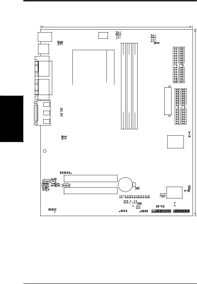
3.1Motherboard Layout
24.5cm (9.64in)
PS/2
T: Mouse
B: Keyboard
USB1 |
USB2 |
COM1 |
PARALLEL PORT |
COM2 |
AUDIO |
Line |
|
|
Out |
|
_ |
Line |
|
In |
||
GAME |
||
In |
||
|
Mic |
|
|
|
|
|
VID4 |
|
|
|
DSW |
VID3 |
|
PALO_FREQ |
|
VID2 |
|
||
KBWK |
|
|
|
|
CPU_RATIO |
VID1 |
|
|
|
|
|
|
||
|
|
|
|
|
USB01_PWR |
|
|
|
THEMCPU |
|
|
|
|
|
|
|
01 |
01 |
01 |
|
|
|
|
|
|
462 Socket |
bit, 184-pin module) |
|
bit, 184-pin module) |
bit, 184-pin module) |
|||
|
|
|
|
|
|
|
|||||||
|
|
|
|
|
|
|
|||||||
|
|
|
|
|
|
|
|
|
|||||
|
|
|
|
|
|
|
|
DIMM1 (64/72 |
|
DIMM2 (64/72 |
DIMM3 (64/72 |
||
|
|
|
|
|
|
|
|
|
|||||
|
|
|
|
VIA |
|
|
|
||||||
|
|
|
|
|
|
DDR |
|
DDR |
DDR |
||||
|
CPU_FAN |
KT266A |
|
|
|
||||||||
|
|
|
|
|
|
|
|
|
|||||
|
PWR_FAN |
Chipset |
|
|
0 |
1 |
2 |
3 |
4 |
5 |
|||
|
|
|
|||||||||||
|
|
|
|||||||||||
|
|
|
|
|
|
|
|
||||||
|
|
|
|
|
|
|
|
||||||
|
|
JP1 |
|
|
|
|
|
|
|
|
|
|
|
|
|
|
||
|
|
JP2 |
|
|
|
|
|
|
|
Accelerated Graphics Port (AGP Pro) |
|
|
||||||
|
|
|
|
|
|
|
|
|
|
|
|
|
||||||
|
|
|
|
|
|
|
|
|
|
|
|
|
|
|
|
|
|
|
|
|
|
|
|
|
|
|
|
|
|
|
|
|
|
|
|
||
|
|
|
|
|
|
|
|
|
|
|
|
|
|
|
DSW |
|
||
LED |
|
Super |
|
|
|
|
|
|
|
|
PCI 1 |
|
SYSCLK |
|||||
|
|
|
|
|
|
|
|
|
|
|
|
|
|
|
|
|
||
|
|
|
|
|
|
|
|
|
|
|
|
|
||||||
|
|
I/O |
|
|
|
|
|
|
|
|
|
|
|
|
|
|
VIA |
|
|
|
|
|
|
|
|
|
|
|
|
|
|
|
|
|
|
|
|
|
|
|
|
|
|
|
|
|
|
|
|
PCI 2 |
|
|
|
|
|
VT8233 |
|
|
2Mb |
|
|
|
|
|
|
|
|
|
|
|
|
|
|
Chipset |
|
|
|
|
|
|
|
|
A7V266-E |
|||||||||||
|
BIOS |
|
|
|
|
|
|
|
|
|
SMARTCARD |
|
||||||
|
|
|
|
|
|
|
|
|
|
|
|
|
|
|
|
|
|
|
AUX |
HPHOME |
|
PCI 3 |
|
|
MIC2 |
|
CR2032 3V |
|
|
|
|
||
|
|
|
|
|
|
|
CD |
|
Lithium Cell |
|
|
|
CMOS Power |
|
|
AAPANEL |
|
|
|
|
|
PCI 4 |
CLR_RTC |
|
BCS MODEM |
|
FLOPPY |
||
|
|
|||
|
|
Media-C CMI87386CH ControllerAudio |
|
|
PCI 5 |
ACRUSB |
|
|
|
|
USB45_ |
PWR |
|
|
|
|
|
|
|
|
|
||||||||||||||
|
|
|
|
|
CHA_FAN |
||||||||||||||||||||||||||||||
|
|
|
|
|
|
|
|
|
|
|
|
|
|
|
|
|
|
|
CHASSIS |
||||||||||||||||
|
|
|
|
|
|
|
|
|
|
|
|
|
|
|
|
|
|
|
IR_CON |
||||||||||||||||
SPDIF OUT |
|
|
|
|
|
|
|
|
|
|
|
|
|
|
|
|
|
|
|
|
CHA |
||||||||||||||
|
|
|
|
|
|
|
|
|
|
|
|
|
|
|
|
|
|
|
|
USB23_PWR |
|
|
|
|
|
|
|
|
|
||||||
|
|
|
|
|
|
|
|
|
|
SMB_CON |
|
|
|
|
|
|
|
|
|
|
|
|
|
||||||||||||
|
|
|
|
|
|
|
|
|
|
|
|
|
|
|
|
|
|
|
|
|
|
|
|
||||||||||||
|
|
|
|
|
ACR |
|
|
|
|
|
|
|
|
|
|
|
|
|
|
|
|
|
|
|
|
|
|
|
|
|
|
|
|
|
|
|
|
|
|
|
|
|
|
|
|
|
|
|
|
|
|
|
|
|
|
|
|
|
|
|
|
|
|
|
|
|
|
|
|
|
|
CDSPDIF IN |
|
|
|
|
USB2_3 |
|
|
USB4_5 |
|
AFPANEL |
|||||||||||||||||||||||||
|
|
|
|
|
|
|
|
||||||||||||||||||||||||||||
|
PR0MISE IDE2 |
|
PR0MISE IDE1 |
ATX Power Connector |
IDE |
|
SecondaryIDE |
|
Primary |
RAID / IDE |
|
|
|
||
|
PROMISE |
|
|
|
IDE |
|
|
|
Controller |
|
|
JTPWR
ASUS
ASIC JEN
with Hardware Monitor


 IDELED
PANEL
30.5cm (12.0in)
14 |
ASUS A7V266-E User’s Manual |

3.HARDWARE SETUP
3.2Layout Contents
Motherboard Settings |
|
|
|
1) |
JEN |
p. 18 |
JumperFree Mode Setting (Disable / Enable) |
2) |
DIP_SW |
p. 19 CPU External Frequency Selection (Switches 1–4) |
|
3) |
DSW |
p. 20 |
Manual CPU Ratio Settings (Switches 1-5) |
4) |
PALO_FREQ |
p. 20 |
FID setting (FID0-3) |
5) |
JP1, JP2 |
p. 20 |
I/O Voltage Settings (2.5V/2.65V/2.75V/2.8V) |
6) |
VID1, 2, 3, 4 |
p. 21 |
Voltage Regulator Output Volt. Setting (1.675V-1.85 V) |
7) |
CENTER/BASS, |
p. 21 |
Bass Center Setting (Type 1 or Type 2) |
|
BASS/CENTER |
|
|
8) |
KBWK |
p. 22 |
Keyboard Power Up (Enable / Disable) |
9) |
ACRUSB1, ACRUSB2 |
p. 22 |
ACR/USB Selection (USB to Conn. / USB on ACR) |
10) |
USB01, 23, 45_PWR |
p. 23 |
Three USB Device Wake-ups (+5V / +5VSB) |
11) |
JP2601 |
p. 23 |
IDE Channel Setting (ATA100 or RAID 1/0) |
12) |
CLR_RTC |
p. 24 |
Clear RTC RAM (2 pin contact) |
13) |
THEMCPU |
p. 24 |
Thermal Sensor CPU Setting (Athlon-Duron / Reserved) |
Expansion Slots/Sockets |
|
|
|
1) |
DIMM 1/2/3 |
p. 25 |
System Memory Support |
2) |
Socket 462 |
p. 27 CPU Support |
|
3) |
PCI 1/2/3/4/5 |
p. 28 |
32-bit PCI Bus Expansion Slots |
4) |
AGP Pro |
p. 30 Accelerated Graphics Port Slot |
|
5) |
ACR Slot |
p. 30 |
Advanced Communication Riser Slot |
Connectors |
|
|
|
1) |
PS2KBMS |
p. 31 PS/2 Mouse Port (6 pin female) |
|
2) |
PS2KBMS |
p. 31 PS/2 Keyboard Port (6 pin female) |
|
3) |
USB |
p. 32 |
Universal Serial Bus Ports 1 & 2 (Two 4 pin female) |
4) |
PRINTER |
p. 32 Parallel Port (25 pin female) |
|
5) |
COM1/COM2 |
p. 32 Serial Ports (9 pin /10-1 pin male) |
|
6) |
GAME_AUDIO |
p. 33 |
Game/MIDI Port (15-pin female) (optional) |
7) |
AUDIO |
p. 33 |
Audio Connectors (Three 1/8” AUDIO) (optional) |
8) |
IDELED |
p. 34 |
IDE Activity LED (2 pin) |
9) |
FLOPPY |
p. 34 Floppy Disk Drive Connector (34 pin) |
|
10) |
PRIMARY / SEC. IDE |
p. 35 IDE Connectors (Two 40-1 pin) |
|
11) |
CPU/PWR/CHA_FAN |
p. 36 |
CPU, Power, and Chassis Fan Connectors (Three 3 pin) |
12) |
USB2_3 / USB4_5 |
p. 36 |
USB Headers (10-1 pin) |
13) |
IR_CON |
p. 37 |
Standard Infrared Module Connector (10-1 pin) |
14) |
AFPANEL |
p. 37 |
ASUS iPanel Connector (12-1 pin) |
15) |
ATXPWR |
p. 38 |
ATX Power Supply Connector (20 pin) |
Layout Contents
3. H/W SETUP
ASUS A7V266-E User’s Manual |
15 |

SETUP H/W .3
Contents Layout
3. HARDWARE SETUP
16) |
SMB |
p. 38 SMBus Connector (5-1 pin) |
|
17) |
CD/AUX/MODEM |
p. 39 Internal Audio Connectors (Three 4-1 pin) (optional) |
|
18) |
MIC2 |
p. 39 Internal Microphone Connector (3 pin) (optional) |
|
19) |
HPHONE |
p. 40 Headphone Line Out connector (3 pin) (optional) |
|
20) |
JTPWR |
p. 40 Power Supply Thermal Sensor (2 pin) |
|
21) |
SPDIFOUT / CDSPDIFIN |
p. 41 Digital audio Interfaces (2 pin) (optional) |
|
22) |
CHASSIS |
p. 41 Chassis Intrusion Lead (2 pin) |
|
23) |
AAPANEL |
p. 42 ASUS iPanel Audio Connector (10-1 pin) |
|
24) |
SMARTCON |
p. 42 ASUS SmartCard Connector (14-1 pin) |
|
25) |
PWR.LED (PANEL) |
p. 43 System Power LED Lead (3 pin) |
|
26) |
KEYLOCK (PANEL) |
p. 43 System Keyboard Lock Switch Lead (2 pin) |
|
27) |
SPEAKER (PANEL) |
p. 43 |
System Warning Speaker Lead (4 pin) |
28) |
MSG.LED (PANEL) |
p. 43 |
System Message LED Lead (2 pin) |
29) |
SMI (PANEL) |
p. 43 |
System Management Interrupt Lead (2 pin) |
30) |
PWR.SW (PANEL) |
p. 43 ATX / Soft-Off Switch Lead (2 pin) |
|
31) |
RESET (PANEL) |
p. 43 |
Reset Switch Lead (2 pin) |
16 |
ASUS A7V266-E User’s Manual |
3.HARDWARE SETUP
3.3Hardware Setup Procedure
Complete the following steps before using your computer:
1.Check motherboard settings
2.Install memory modules
3.Install the Central Processing Unit (CPU)
4.Install Expansion Cards
5.Connect ribbon cables, panel wires, and power supply cables
6.Configure the BIOS parameter settings
3.4Motherboard Settings
This section tells you how to change motherboard function settings through the switches and/or jumpers.
WARNING! Computer motherboards and expansion cards contain very delicate Integrated Circuit (IC) chips. To avoid damaging them due to static electricity, follow these precautions whenever you work on your computer.
1.Unplug the computer when working on the internal components.
2.Use a grounded wrist strap or touch a safely grounded object or to a metal object, such as the power supply case, before handling computer components.
3.Hold components by the edges and try not to touch the IC chips on them.
4.Whenever you uninstall any component, place the components on a grounded antistatic pad or in the bag that came with the components.
5.Before you install or remove any component, ensure that the ATX power supply is switched off or the power cord is detached from the power supply. Failure to do so may cause severe damage to the motherboard, peripherals, and/or components.
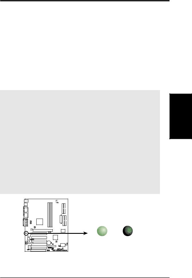
(TIP: When lit, the onboard LED indicates that the system is in suspend or soft-off mode, not powered OFF. See illustration below.)
|
|
|
|
|
|
|
|
|
|
|
|
|
|
|
|
|
|
|
|
|
|
|
01 |
01 |
1 |
0 |
|
|
|
|
|
|
|
||||||||
|
|
|
|
|
|
|
|
|
|
|
|
|
|
|
|
|
|
|
|
|
|
|
|
|
|
|
|
|
|
|
|
|
|
|
|
|
|
|
|
|
|
|
|
|
|
|
|
|
|
|
|
|
|
|
|
|
|
|
|
|
|
|
|
|
|
|
|
|
|
LED
A7V266-E |
ON |
OFF |
|
Standby |
Powered |
|
Power |
Off |
A7V266-E Onboard LED
Motherboard Settings
3. H/W SETUP
ASUS A7V266-E User’s Manual |
17 |
SETUP H/W .3
Settings Motherboard
3. HARDWARE SETUP
Motherboard Frequency Settings (DIP Switches)
The motherboard frequency is adjusted through the DIP switches. The white block represents the switch’s position. The illustration below shows all the switches in the OFF position.
CPU_RATIO
01 |
1 |
0 |
1 |
0 |
|
|
|
|
|
|
|
|
|
|
|
|
|
ON
ON


 OFF
OFF
1 2 3 4 5
SYSCLK |
|
|||
ON |
2 |
3 |
4 |
|
1 |
ON |
|||
A7V266-E |
|
|
|
|
|
|
|
|
OFF |
A7V266-E DIP Switch
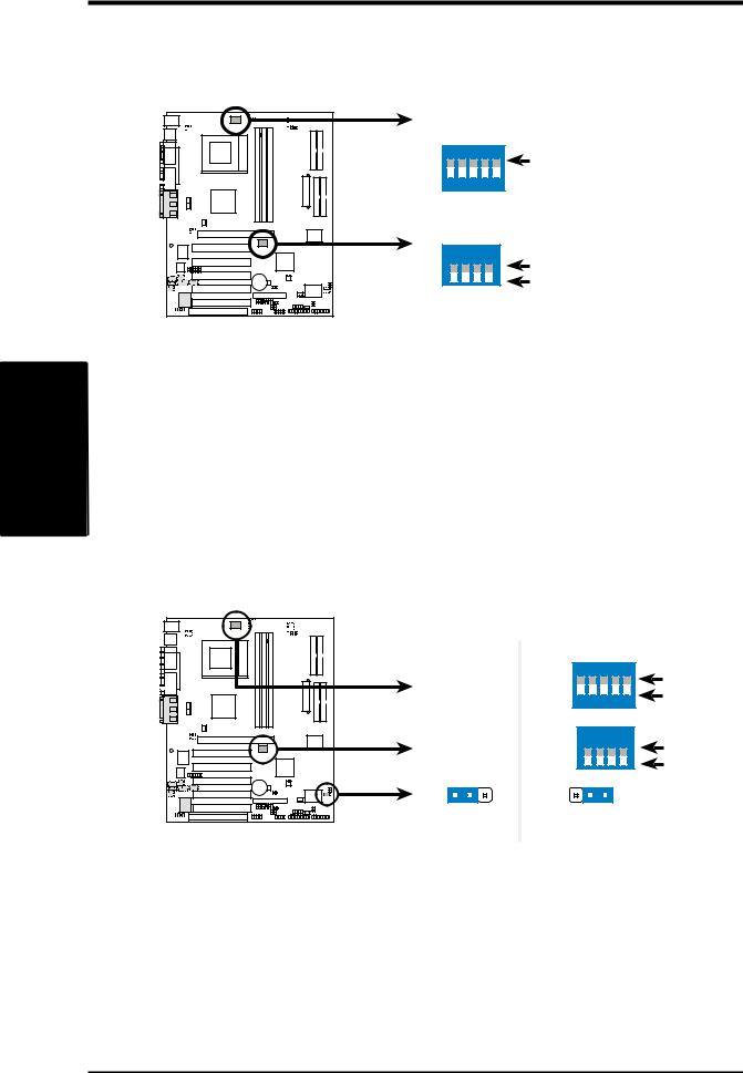
1) JumperFree™ Mode (JEN)
This jumper allows you to enable or disable the JumperFree™ mode. The
JumperFree™ |
|
|
mode allows processor settings to be made through the BIOS |
||||||||
setup (see 4.4 Advanced Menu). |
|
|
|
|
|
|
|
||||
Setting |
|
|
|
JEN |
|
|
|
|
|
|
|
Enable (JumperFree) |
[2-3] (default) |
|
|
|
|
|
|
||||
Disable (Jumper Mode) |
[1-2] |
|
|
|
|
|
|
|
|||
|
|
|
|
|
JEN |
|
|
|
|
|
|
01 |
1 |
0 |
01 |
|
|
|
|
|
|
|
|
|
|
|
|
|
|
CPU_RATIO |
|
|
|
||
|
|
|
|
|
|
ON |
|
|
|
ON |
|
|
|
|
|
|
|
|
|
|
|
|
|
|
|
|
|
|
|
1 |
2 |
3 |
4 |
5 |
OFF |
|
|
|
|
|
|
|
|||||
|
|
|
|
|
|
SYSCLK |
|
|
|
|
|
|
|
|
|
|
|
ON |
2 |
3 |
4 |
|
|
|
|
|
|
|
|
|
1 |
ON |
|||
|
|
|
|
|
|
|
|
|
|
|
|
A7V266-E |
|
|
|
|
|
|
|
|
OFF |
||
|
1 |
2 |
|
2 |
3 |
|
|
|
|||
|
|
|
|
|
|
|
|
||||
|
|
|
|
Jumper Mode |
Jumper Free |
|
|||||
A7V266-E Jumper Mode Setting |
|
(Default) |
|
|
|||||||
NOTE: In JumperFree™ mode, set all DIP switches (DIP_SW) to OFF.
18 |
ASUS A7V266-E User’s Manual |
3.HARDWARE SETUP
2)CPU External Frequency Selection (DIP_SW Switches 1–4)
This option tells the clock generator what frequency to send to the CPU, DRAM, and the PCI bus. This allows the selection of the CPU’s External frequency (or BUS Clock). The BUS Clock multiplied by the Frequency Multiple equals the CPU’s Internal frequency (the advertised CPU speed).
|
|
|
|
|
|
|
|
|
|
|
|
|
|
|
|
|
|
|
|
|
|
|
|
|
|
|
|
|
|
|
|
|
|
|
|
|
01 |
01 |
1 |
0 |
|||||||
|
|
|
|
|
|
|
|
|
|
|
|
|
|
|
|
|
|
|
|
|
|
|
|
|
|
|
|
|
|
|
|
|
|
|
|
|
|
|
|
|
|
|
|
|
|
|
|
|
|
|
|
|
|
|
SYSCLK |
|
|
|
|
|
|
|
|
|
|
|
|
|
|
|
|
|
|
|
|
|
|||||||
|
|
|
|
|
|
|
|
|
|
|
|
|
|
|
|
|
|
|
|
|
|
|
|
|
|
|
|
|
|
|
|
|
|
|
|
|
|
|
|||||||||
|
|
|
|
|
|
|
|
|
|
|
|
|
|
|
|
|
|
|
|
|
|
|
|
|
|
|
|
|
|
|
|
|
|
|
|
|
|
|
|
|
|
|
|
|
|
|
|
|
|
|
|
|
|
|
|
|
|
|
|
|
|
|
|
|
|
|
|
|
|
|
|
|
|
|
|
|
|
|
|
|
|
|
|
|
|
|
|
|
|
|
|
|
|
|
|
|
|
|
|
|
|
|
|
|
|
|
|
|
|
|
|
|
|
|
|
ON |
|
|
|
|
|
ON |
|
|
|
|
|
ON |
|
|
|
|
|
ON |
|
|
|
|
|
||||
|
|
|
|
|
|
|
|
|
|
|
|
|
|
|
|
|
|
|
|
1 |
2 |
3 |
4 |
|
|
1 |
2 |
3 |
4 |
|
|
1 |
2 |
3 |
4 |
|
|
1 |
2 |
3 |
4 |
|
|
||||
|
|
|
|
|
|
|
|
|
|
|
|
|
|
|
|
|
|
|
|
|
|
|
|
|
|
|
|
||||||||||||||||||||
|
|
|
|
|
|
|
|
|
|
|
|
|
|
|
|
|
|
|
|
|
|
|
|
|
|
|
|
|
|
|
|
|
|
|
|
|
|
|
|
|
|
|
|
|
|
|
|
|
|
|
|
|
|
|
|
|
|
|
|
|
|
|
|
|
|
|
|
|
|
|
|
|
|
|
|
|
|
|
|
|
|
|
|
|
|
|
|
|
|
|
|
|
|
|
|
|
|
|
|
|
|
|
|
|
|
|
|
|
|
|
|
|
|
|
CPU |
|
100MHz |
133.33MHz 140MHz |
|
|
|
|
|
|
|
|
|||||||||||||||||
|
|
|
|
|
|
|
|
|
|
|
|
|
|
|
|
|
|
|
|
|
|
|
|
|
|
|
|
||||||||||||||||||||
|
|
|
|
|
|
|
|
|
|
|
|
|
|
|
|
|
|
|
|
|
|
|
|
|
|
|
|
||||||||||||||||||||
|
|
|
|
|
|
|
|
|
|
|
|
|
|
|
|
|
|
|
|
|
|
|
|
|
|||||||||||||||||||||||
|
|
|
|
|
|
|
|
|
|
|
|
|
|
|
|
|
|
|
AGP 60.67MHz |
66.67MHz |
70MHz |
(JumperFree Mode) |
|||||||||||||||||||||||||
|
|
|
|
|
|
|
|
|
|
|
|
|
|
|
|
|
|||||||||||||||||||||||||||||||
|
|
|
|
|
|
|
A7V266-E |
|
|
|
|
|
|
|
|
|
|
|
|
|
|
|
|
|
|
|
|
|
|
|
|
|
|
|
|
||||||||||||
|
|
|
|
|
|
|
|
|
|
|
|
|
|
|
|
|
|
|
PCI |
33.33MHz |
33.33MHz |
35MHz |
|
|
|
|
|
|
|
|
|||||||||||||||||
|
|
|
|
|
|
|
|
|
|
|
|
|
|
|
|
|
|
|
|
|
|
|
|
|
|
|
|
|
|
|
|
|
|
|
|
|
|
|
|
|
|
|
|
|
|
|
|
|
|
|
|
|
|
|
|
|
|
|
|
|
|
|
|
|
|
|
|
|
|
|
|
|
|
|
|
|
|
|
|
|
|
|
|
|
|
|
|
|
|
|
|
|
|
|
|
|
|
|
|
|
|
|
|
|
|
|
|
|
|
|
|
|
|
|
|
|
|
|
|
|
|
|
|
|
|
|
|
|
|
|
|
|
|
|
|
|
|
|
|
|
|
|
|
|
|
|
|
|
|
|
|
|
|
|
|
|
|
|
|
|
|
|
|
|
|
|
|
|
|
|
|
|
|
|
|
|
|
|
|
|
|
|
|
|
|
|
|
|
|
|
|
A7V266-E CPU External
Frequency Selection
WARNING! Set the CPU frequency only to the recommended settings. Frequencies other than the recommended CPU bus frequencies are not guaranteed to be stable. Overclocking the processor is not recommended. It may result in a slower speed.
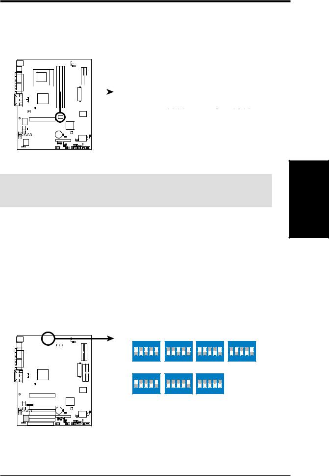
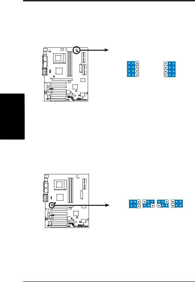
3)Manual CPU Ratio Settings (DSW Switches 5-10)
Set DSW switches (5-10) to use the clock multiplier to coordinate the ratio of bus speeds with CPU settings. Set the DSW switches according to the internal speed of your processor and the bus frequency (133/100MHz).
IMPORTANT: |
|
1. To use this feature, JEN must |
be set to Jumper Mode, [1-2]. |
(See 1, JumperFree™ Mode (JEN) |
in 3, HARDWARE SETUP.) |
2.When JumperFree mode is enabled, use BIOS setup in place of these switches. (Set Operating Frequency Setting to User Define under 4.4 Advanced Menu in BIOS Setup so you can set the CPU Frequency.)
CPU_RATIO
|
|
|
|
|
|
|
|
|
|
|
|
|
|
|
|
|
|
|
|
|
|
|
|
|
|
|
|
|
|
|
|
|
|
|
|
|
|
|
|
|
|
|
|
|
|
|
|
|
|
01 |
|
01 |
0 |
|
|
|
|
|
|
|
|
|
|
|
|
|
|
|
|
|
|
|
|
|
|
|
|
|
|
|
|
|
|
|
|
|
|
|
|
|
|
|
|
|
|
|
|
|
|
|
|
|
|
|
|
|
|
|
|
|
|
|
|
|
|
|
|
|
|
|
|
|
|
|
|
|
|
|
|
|
|
|
|
|
|
|
|
|
|
|
|
|
|
|
|
|
|
|
|
|
|
|
|
|
|
|
|
|
|
|
|
|
|
|
|
|
|
|
|
|
|
|
|
|
|
|
|
|
|
|
|
|
|
|
|
|
|
|
|
|
|
|
|
|
|
|
|
|
|
|
|
|
|
|
|
|
|
|
|
|
|
|
|
|
|
|
|
|
|
|
|
|
|
|
|
|
|
|
|
|
|
|
|
|
|
|
|
|
|
|
|
|
|
|
|
|
|
|
|
|
|
|
|
|
|
|
|
|
|
|
|
|
|
|
|
|
|
|
|
A7V266-E
ON
1 2 3 4 5
CPU_RATIO 8X
ON |
|
|
|
|
1 |
2 |
3 |
4 |
5 |
CPU_RATIO 10X
ON |
ON |
ON |
1 2 3 4 5 |
1 2 3 4 5 |
1 2 3 4 5 |
8.5X |
9X |
9.5X |
ON |
|
|
|
ON |
|
|
|
||
1 |
2 |
3 |
4 |
5 |
1 |
2 |
3 |
4 |
5 |
10.5X (JumperFree Mode)
A7V266-E CPU External
Clock (BUS) Frequency
Selection
Motherboard Settings
3. H/W SETUP
ASUS A7V266-E User’s Manual |
19 |
SETUP H/W .3
Settings Motherboard
3.HARDWARE SETUP
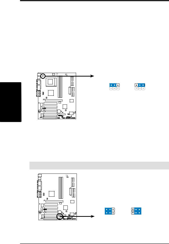
4)CPU Type Frequency Setting (PALO_FREQ)
This jumper setting accomodates the difference between the internal frequency between standard and new AMD CPUs. If changing from one type of CPU to another, the jumper caps must be adjusted. The factory default setting, [2-3], is for standard Athlon/Duron CPUs. The Palomino processor will only function on this motherboard after the jumpers are adjusted to [1-2].
|
|
|
|
PALO_FREQ |
|
|
|
||
01 |
1 |
0 |
1 |
0 |
|
|
|
|
|
|
|
|
|
1 |
2 |
3 |
1 |
2 |
3 |
|
|
|
|
FID0 |
|
|
FID0 |
|
|
|
|
|
|
FID1 |
|
|
FID1 |
|
|
|
|
|
|
FID2 |
|
|
FID2 |
|
|
|
|
|
|
FID3 |
|
|
FID3 |
|
|
|
|
|
|
PALOMINO |
ATHLON/DURON |
||||
|
|
|
|
|
|
|
(Default) |
|
|
A7V266-E
A7V266-E PALO_FREQ Setting
5)I/O Voltage Settings (JP1, JP2)
These jumpers allow you to select the voltage supplied to the DRAM, chipset, AGP, and PCI. The default setting for the jumpers is: JP1 [2-3] and JP2 [1-2], 2.65 volts. Use the default setting for better system reliability.
|
|
|
|
|
|
|
|
|
|
|
|
|
|
|
|
|
|
|
|
|
|
|
|
|
|
|
|
|
|
|
|
|
|
1 |
0 |
01 |
01 |
||||||
|
|
|
|
|
|
|
|
|
|
|
|
|
|
|
|
|
|
|
|
|
|
|
|
|
|
|
|
|
|
|
|
|
JP1/JP2
|
|
|
|
|
|
|
3 |
1 2 3 |
1 2 3 |
1 2 3 |
|
|
|
|
|
|
|
||||
|
|
|
|
|
|
|
||||
|
|
|
|
|
|
1 2 |
||||
|
|
|
|
|
||||||
|
|
|
|
|
|
|
|
|
|
|
JP1 |
JP2 |
2.5V |
2.65V |
2.75V |
2.8V |
A7V266-E
(Default)
A7V266-E Voltage Setting
20 |
ASUS A7V266-E User’s Manual |
3.HARDWARE SETUP
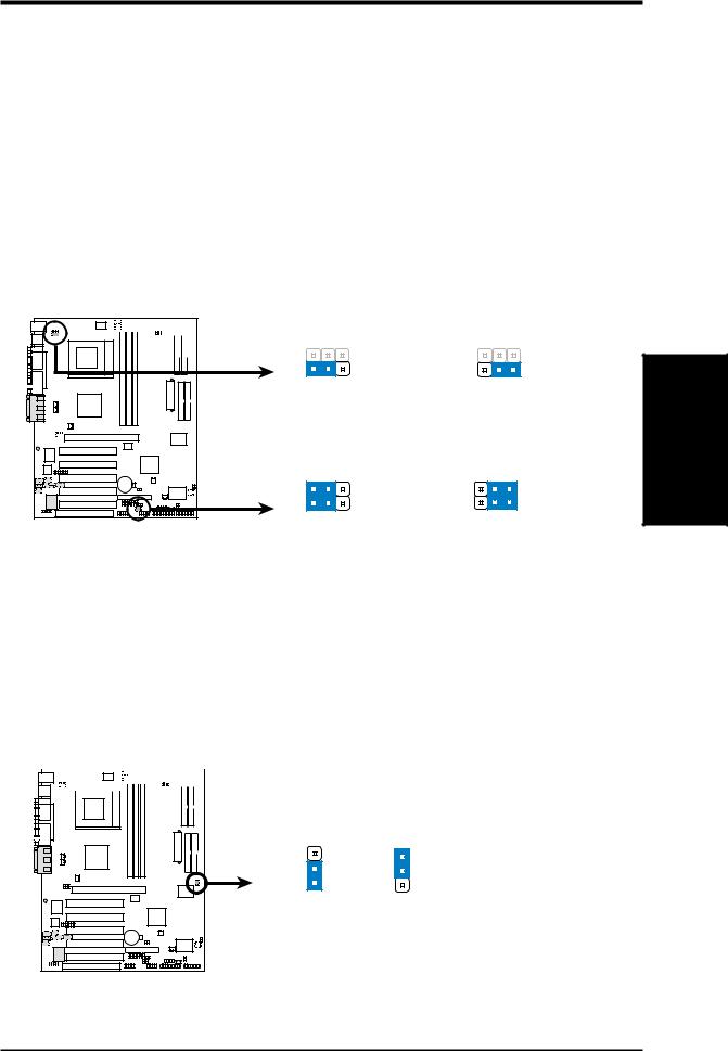
6)Voltage Regulator Output Setting (VID1, VID2, VID3, VID4)
This jumpers allow you to manually adjust the CPU core voltage. It is recommended to use CPU Default as the CPU core voltage. CPU Default, all jumpers [2-3], means the Vcore is generated according to the CPU VID configuration. For each jumper setting, there are two voltage options, depending on the CPU used.
|
|
|
|
|
|
1 |
2 |
3 |
1 |
2 |
3 |
|
|
|
|
|
|
VID4 |
|
|
|
|
|
1 |
0 |
01 |
01 |
|
|
VID3 |
|
|
|
|
|
|
|
|
|
|
|
|
|
|
|
|
|
|
|
|
1 |
2 |
3 |
VID2 |
|
|
|
|
|
|
|
|
|
|
|
|
|
|
|||
|
|
|
VID4 |
|
|
VID1 |
|
|
|
|
|
|
|
|
VID3 |
|
|
1.85/1.825Volts |
1.8/1.775Volts |
||||
|
|
|
VID2 |
|
|
1 |
2 |
3 |
1 |
2 |
3 |
|
|
|
VID1 |
|
|
||||||
|
|
|
CPU Default |
VID4 |
|
|
|
|
|
||
|
|
|
VID3 |
|
|
|
|
|
|||
|
|
|
|
|
|
|
|
|
|
|
|
|
|
|
|
|
|
VID2 |
|
|
|
|
|
A7V266-E |
|
|
|
VID1 |
|
|
|
|
|
||
|
|
|
|
|
|
|
|
|
|
|
|
|
|
|
|
|
|
1.75/1.725Volts |
1.7/1.675Volts |
||||
A7V266-E CPU Core Voltage
Selection
7)Bass Center Setting (CENTER/BASS, BASS/CENTER)
Use these jumpers in conjunction with the C-Media PCI Audio Driver and to adjust output for 4 or 6 speaker audio. No audio standard exists for the three pick-up surfaces on male audio jacks, therefore it may be necessary to switch jumpers from the default position, type 1, to type 2, in order to help reroute signals among the internal leads in the Line-In, Line-Out, Mic female sockets. Make sure a test is made using the C-Media Audio Driver software setup available on the Support CD.
|
|
|
|
|
|
|
|
|
|
|
|
|
|
|
|
|
|
|
|
|
|
|
01 |
01 |
1 |
0 |
|
|
|
|
|
|
|
||||||||
|
|
|
|
|
|
|
|
|
|
|
|
|
|
|
|
|
|
|
|
|
|
|
|
|
|
|
|
|
|
|
|
|
|
|
|
|
|
|
|
|
|
|
BCS |
|
|
1 |
2 |
2 |
3 |
A7V266-E |
|
type 2 Bass |
|
type 1 Bass |
|||
(CENTER/BASS) |
(BASS/CENTER) |
||
(Default) |
|
|
|
A7V266-E Bass Center
Setting
Motherboard Settings
3. H/W SETUP
ASUS A7V266-E User’s Manual |
21 |
SETUP H/W .3
Settings Motherboard
3.HARDWARE SETUP
8)Keyboard Wake Up (KBWK)
This allows you to disable or enable the keyboard power up function. Set this jumper to Enable if you wish to use your keyboard (by pressing <Spacebar>) to power up your computer. This feature requires an ATX power supply that can supply at least 300mA on the +5VSB lead. The default is set to Enable. (The computer will not power ON if you set this to Enable but do not have the correct ATX power supply. NOTE: This jumper must be set in conjunction with Wake On PS2 KB/PS2 Mouse/CIR in 4.5.1 Power Up Control.
Setting |
|
|
KBWK |
|
|
Enable |
|
|
[1-2] (default) |
|
|
Disable |
|
|
[2-3] |
|
|
|
|
|
|
|
KBWK |
01 |
1 |
0 |
01 |
|
|
|
|
|
1 |
2 |
2 3 |
|
|
|
Enable |
Disable |
|
|
|
|
(Default) |
|
|
A7V266-E |
|
|
|
||
A7V266-E Keyboard Wake Up
9)ACR/USB Selection (ACRUSB1, ACRUSB2) (audio models only)
When set to pins 1-2, these jumpers allow you to activate USB port 3. Setting the jumpers to pins 2-3 activates the Advanced Communication Riser (ACR) slot. The default setting for both jumpers is 1-2. (NOTE: The USB port 2 is always active regardless of the setting of these jumpers.)
IMPORTANT! Always set both jumpers accordingly when selecting a device.
|
|
|
|
|
|
|
|
|
|
|
|
|
|
|
|
|
|
|
|
|
|
|
1 |
0 |
1 |
0 |
01 |
|
|
|
|
|
|
||||||||
|
|
|
|
|
|
|
|
|
|
|
|
|
|
|
|
|
|
|
|
|
|
|
|
|
|
|
|
|
|
|
|
|
|
|
|
|
|
|
|
|
|
|
|
|
|
|
|
|
|
|
|
|
|
|
|
|
|
|
|
|
|
|
|
|
|
|
|
|
|
|
ACRUSB |
|
|
1 |
2 |
2 |
3 |
A7V266-E |
|
|
|
USB to Conn. |
USB on ACR |
||
A7V266-E USB/ACR Selection
22 |
ASUS A7V266-E User’s Manual |
3.HARDWARE SETUP
10)USB Device Wake-up (USB01_PWR/USB23_PWR/USB45_PWR)
Set these jumpers to +5V to allow wake up from the S1 sleep state (CPU stopped; RAM refreshed; system running in low power mode) using the connected USB devices. Set to +5VSB to allow wake up from S3 sleep state (no power to CPU; RAM in slow refresh; power supply in reduced power mode). The default setting for the three jumpers is 1-2 to select +5V (because not all computers have the appropriate power supply).
NOTES:
1.This feature requires an ATX power supply that can supply at least 2A on the +5VSB lead when these jumpers are set to +5VSB. Otherwise, the system does not power up.
2.The total current consumed must NOT exceed the power supply capability (+5VSB) whether under normal working conditions or in sleep mode.
|
|
|
|
|
|
|
|
|
|
|
|
|
1 |
2 |
2 |
3 |
|
|
|
|
|
|
|
|
|
|
|
|
|
||||
|
|
|
01 |
1 |
0 |
01 |
|
|
|
|
||||||
|
|
|
|
|
|
|
|
|||||||||
|
|
|
|
|
|
|
|
|
|
|
|
|
|
|
|
|
|
|
|
|
|
|
|
|
|
|
|
|
|
|
|
|
|
|
|
|
|
|
|
|
|
|
|
|
|
|
|
|
|
|
|
|
|
|
|
|
|
|
|
|
|
|
|
|
|
|
|
|
USB01_PWR |
+5V |
+5VSB |
A7V266-E |
1 |
2 |
2 |
3 |
|
USB23_PWR |
USB45_PWR |
+5V |
+5VSB |
A7V266-E USB Device Wake Up
11)IDE Channel Setting for ATA100 or RAID 0/1 (JP2601)
These jumpers enable the ATA100 IDE Controller, or the IDE RAID
controller function. The default setting enables ATA100.
Setting |
|
|
|
|
|
|
|
JP2601 |
|||||||
Enable ATA100 |
|
|
|
[1-2] (default) |
|||||||||||
Enable RAID 0/1 |
[2-3] |
||||||||||||||
|
|
|
|
|
|
|
|
|
|
|
|
|
|
|
|
|
|
|
|
|
|
|
|
|
|
|
|
|
|
||
|
|
|
|
|
|
|
|
|
|
|
|
|
|
|
|
|
|
|
|
01 |
1 |
0 |
01 |
|
|
|
|
|
|
||
|
|
|
|
|
|
|
|
|
|
||||||
|
JP2601 |
|
3 |
2 |
2 |
1 |
|
ATA100 RAID0/1
A7V266-E |
(Default) |
A7V266-E ATA100/RAIDO Selection
Motherboard Settings
3. H/W SETUP
ASUS A7V266-E User’s Manual |
23 |
SETUP H/W .3
Settings Motherboard
3.HARDWARE SETUP
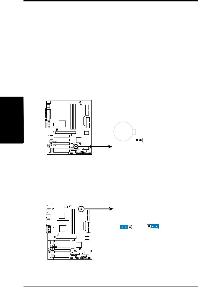
12)Clear RTC RAM (2-pin CLR_RTC)
This jumper allows you to clear the Real Time Clock (RTC) RAM in CMOS. You can clear the CMOS memory of date, time, and system setup parameters by erasing the CMOS RTC RAM data. The RAM data in CMOS, that include system setup information such as system passwords, is powered by the onboard button cell battery.
To erase the RTC RAM:
1.Turn OFF the computer and unplug the power cord.
2.Remove the battery.
3.Short the jumper by removing and replacing the jumper cap.
4.Re-install the battery.
5.Plug the power cord and turn ON the computer.
6.Hold down the <Del> key during the boot process and enter BIOS setup to re-enter data.
|
|
|
|
|
|
|
|
|
|
|
|
|
|
|
|
|
|
|
|
|
|
|
|
|
01 |
01 |
1 |
0 |
|
|
|
|
|
|
|
|
|
|
||||||
|
|
|
|
|
|
|
|
|
|
|
|
|
|
|
|
|
|
|
|
|
|
|
|
|
|
|
|
|
|
|
|
|
|
|
|
|
|
|
|
|
|
|
|
|
|
|
|
|
|
|
|
|
|
|
|
|
|
|
|
|
|
|
|
|
|
|
|
|
|
|
|
|
|
|
|
|
|
|
|
|
|
|
|
|
|
|
|
|
|
CR2032 3V
Lithium Cell
CMOS Power
CLRTC
A7V266-E
Remove and then replace the jumper cap.
A7V266-E Clear RTC RAM
13)Thermal Sensor CPU Setting (2-pin THEMCPU)
This jumper selects the type of CPU and coordinates its thermal sensory capability. The default setting, [1-2], is for Athlon/Duron and, [2-3], is for Reserve type processors.
01 |
1 |
0 |
01 |
THEMCPU |
|
|
|
|
|
1 |
2 |
2 |
3 |
|
|
|
ATHLON/DURON |
RESERVED |
||
|
|
|
(Default) |
|
|
|
A7V266-E
A7V266-E THEMCPU Setting
24 |
ASUS A7V266-E User’s Manual |

3.HARDWARE SETUP
3.5System Memory
This motherboard features three Double Data Rate (DDR) Dual Inline Memory Module sockets.
3.5.1 DDR DIMM Support
The three DDR DIMM sockets support 2.5Volt (power level) unbuffered/registered Double Data Rate Synchronous Dynamic Random Access Memory (DDR SDRAM) of 64MB, 128MB, 256MB, 512MB, and 1GB to form a memory size between 64MB to 3GB. One side (with memory chips) of the DIMM takes up one row on the motherboard. DDR DIMMs support non-ECC memory (used on desktops/laptops).
Install memory in any combination as follows:
DIMM Location |
184-pin DDR DIMM |
Total Memory |
Socket 1 (Rows 0&1) |
64MB, 128MB, 256MB, 512MB, 1GB |
x1 |
|
|
|
Socket 2 (Rows 2&3) |
64MB, 128MB, 256MB, 512MB, 1GB |
x1 |
|
|
|
Socket 3 (Rows 4&5) |
64MB, 128MB, 256MB, 512MB, 1GB |
x1 |
|
|
|
|
Total System Memory (Max 3GB) |
= |
|
|
|
System Memory
3. H/W SETUP
ASUS A7V266-E User’s Manual |
25 |
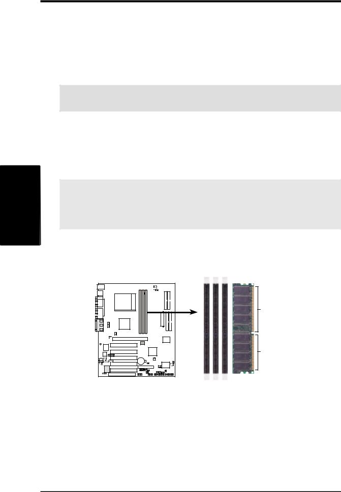
3.HARDWARE SETUP
3.5.2General DIMM Notes
•DIMMs that have more than 18 chips are not supported on this motherboard.
•ASUS motherboards support SPD (Serial Presence Detect) DIMMs. This is the memory of choice for best performance vs. stability.
•BIOS shows SDRAM memory on bootup screen.
•Single-sided DDR DIMMs come in 64, 128, and 256MB; double-sided come in 128, 256, and 512MB.
WARNING! Be sure that the DIMMs you use can handle the specified DDR RAM MHz or else bootup will not be possible.
System |
3.H/W |
Memory |
SETUP |
3.5.3 Memory Installation
WARNING! Make sure that you unplug your power supply when adding or removing memory modules or other system components. Failure to do so may cause severe damage to both your motherboard and expansion cards (see 3.3 Hardware Setup Procedure for more information).
Insert the module(s) as shown. Because the number of pins are different on either side of the breaks, the module will only fit in the orientation shown. A 184-pin DDR DRAM DIMM has a single notch slightly to the right of center.
|
|
|
|
|
|
|
|
|
|
|
|
|
|
|
|
|
|
|
|
|
|
|
|
|
|
|
|
|
|
|
|
|
|
|
|
|
1 |
0 |
01 |
01 |
|||||||
|
|
|
|
|
|
|
|
|
|
|
|
|
|
|
|
|
|
|
|
|
|
|
|
|
|
|
|
|
|
|
|
|
|
|
|
104 Pins
80 Pins
A7V266-E
A7V266-E 184-Pin DDR
DIMM Sockets
26 |
ASUS A7V266-E User’s Manual |
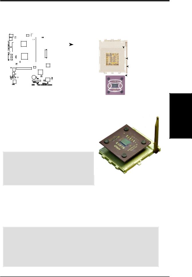
3.HARDWARE SETUP
3.6Central Processing Unit (CPU)
The motherboard provides a Socket 462 or Socket A for CPU installation. A fan and heatsink should be attached to the CPU to prevent overheating. Purchase and install a fan and heatsink before turning on the system.
|
|
|
|
|
|
|
|
|
|
|
|
|
|
|
|
|
|
|
|
|
|
|
|
|
|
|
|
|
|
|
|
|
|
|
|
|
|
|
|
|
|
1 |
0 |
01 |
01 |
|
|
|
|
|
|
|
|
CPU NOTCH |
|
|
|
|
|
|
|
||
|
|
|
|
|
|
|
|
|
|
|
|
|
|
|
|
|
|
|
|
|
|
|
|
|
|
|
|
|
|
|
|
|
|
|
|
|
|
|
|
|
|
|
|
|
|
|
|
|
|
|
|
|
|
|
|
|
|
|
|||||
|
|
|
|
|
|
|
|
|
|
|
|
|
|
|
|
|
|
|
|
|
|
|
|
TO INNER |
|
|
|
|
|
|
|
|
|
|
|
|
|
|
|
|
|
|
|
|
|
|
|
|
|
|
|
|
|
|
|
CORNER |
|
|
|
|
|
LOCK |
|
|
|
|
|
|
|
|
|
|
|
|
|
|
|
|
|
|
|
|
|
|
|
|
|
|
|
|
|
||||
|
|
|
|
|
|
|
|
|
|
|
|
|
|
|
|
|
|
|
|
|
|
|
|
|
|
|
|
|
|
|
|
|
|
|
|
|
|
|
|
|
|
|
|
|
|
|
|
|
|
|
|
|
|
|
|
|
|
|
|
|
|
|
|
|
|
|
|
|
|
|
|
|
|
|
|
|
|
|
|
|
|
|
|
|
|
|
|
|
|
|
|
|
|
|
|
|
|
|
|
|
|
|
|
|
|
|
|
|
|
|
|
|
|
|
|
|
|
|
|
|
|
|
|
|
|
|
|
|
|
|
|
|
|
|
|
|
|
|
|
|
|
|
|
|
|
|
|
|
|
|
|
|
|
|
|
|
|
|
|
|
|
|
|
|
|
|
|
|
|
|
|
|
|
|
|
|
|
|
|
|
|
|
|
|
|
|
|
|
|
|
LEVER |
|
|
|
|
|
|
|
|
|
|
|
|
|
|
|
|
|
|
|
|
|
|
|
|
|
|
|
|
|
|
|
|
|
|
|
|
|
|
|
|
|
|
|
|
|
|
|
|
|
|
|
|
|
|
|
|
|
|
|
|
|
|
|
|
|
|
|
|
|
|
|
|
|
|
|
|
|
|
|
|
|
|
|
|
|
|
|
|
|
|
|
|
||||
|
|
|
|
|
|
|
|
|
|
|
|
|
|
|
|
|
|
|
|
|
|
|
|
|
|
|
|
|
|
|
|
|
|
|
|
|
|
|
|
|
|
|
|
|
|
|
|
|
|
|
|
|
|
|
|
|
|
|
|
|
|
|
|
|
|
|
|
|
|
|
A7V266-E |
|
AMD™ CPU |
|
|
|
CPU NOTCH |
||||||||||||||||||
|
|
|
|
|
|
|
|
|
|
|
|
|
|
|
|
|
|
|
|
|
|
|
|
|
|
|
|||||
|
|
|
|
|
|
|
|
|
|
|
|
|
|
|
|
|
|
|
|
|
|
|
|
|
|
|
|
||||
|
|
|
|
|
|
|
|
|
|
|
|
|
|
|
|
|
|
|
|
|
|
|
|
|
|
|
|||||
|
|
|
|
|
|
|
|
|
|
|
|
|
|
|
|
|
|
|
|
|
|
|
|
|
|
|
|
|
|
|
|
|
|
|
|
|
|
|
|
|
|
|
|
|
|
|
|
|
|
|
|
|
|
|
|
|
|
|
|
|
|
|
|
A7V266-E Socket A
1.Locate the Socket 462 and open it by pulling the lever gently sideways away from the socket. Then lift the lever upwards. The socket lever must be fully opened (90 to 100 degrees).
2.Insert the CPU with the correct orientation. The notched corner of the CPU must be oriented toward the inner corner of the socket base nearest to the lever hinge.
CAUTION! The CPU fits in one orientation and should drop easily into place. Do not force the CPU into the socket to avoid bending the pins. If the CPU does not fit, check its alignment and look for bent pins.
3.Once completely inserted, press the CPU firmly
and close the socket lever until it snaps into its locked position.
4.Place the CPU fan and heatsink on the CPU. The heatsink should entirely cover the CPU. Carefully attach the heatsink locking brace to the plastic clips on the socket base. With the added weight of the CPU fan and heatsink locking brace, no extra force is required to keep the CPU in place.
CAUTION! Take care not to scrape the motherboard surface when mounting a clamp-style processor fan, or else damage may occur. When mounting a heatsink onto your CPU, make sure that exposed CPU capacitors do not touch the heatsink, or else damage may occur! Refer to heatsink/CPU documentation. NOTE! Do not forget to set the correct Bus Frequency and Multiple (available only on unlocked processors) to avoid start-up problems.
System Memory
3. H/W SETUP
ASUS A7V266-E User’s Manual |
27 |
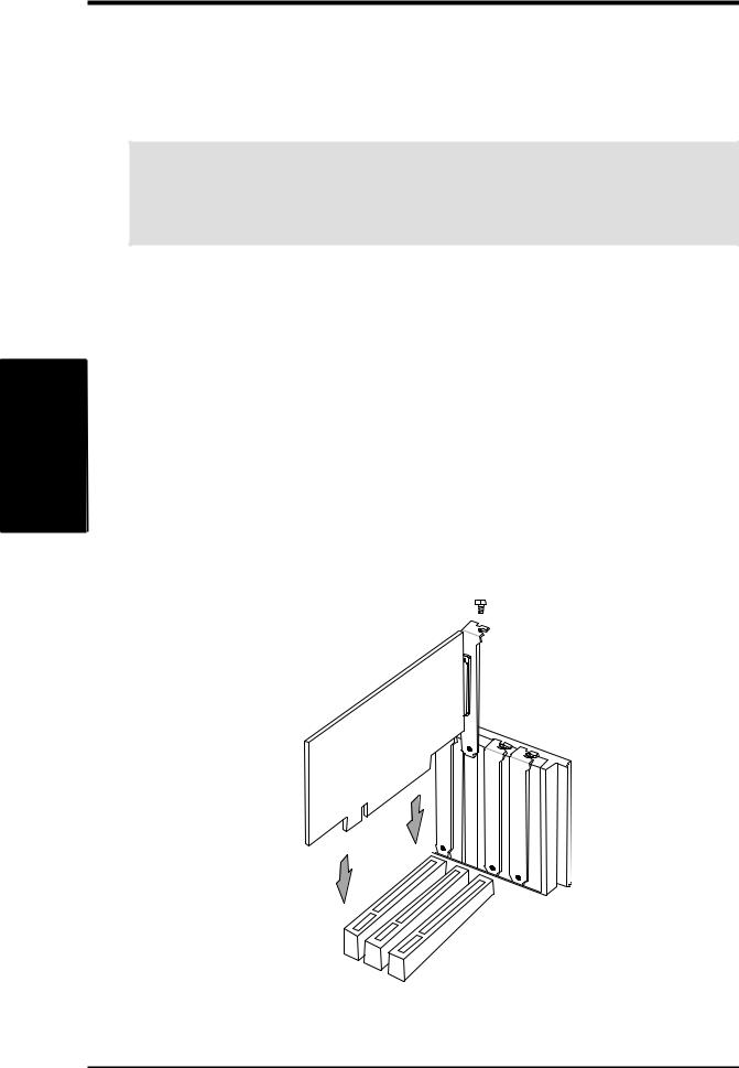
3CPU H/W . SETUPInstallation
3.HARDWARE SETUP
3.7Expansion Cards
In the future, you may need to install expansion cards. The motherboard has five PCI expansion slots to support these cards. Follow the steps in the next section when installing expansion cards.
WARNING! Unplug the system power cord when adding or removing expansion cards or other system components. Failure to do so may cause severe damage to both the motherboard and expansion cards.
3.7.1 Installing an Expansion Card
1.Read the documentation that comes with the expansion card and make any necessary hardware settings for the card before installing it.
2.Remove the system unit cover and the bracket plate on the slot you intend to use. Keep the screw for later use.
3.Align the card connectors with the slot and press firmly until the card fits in place.
4.Secure the card to the slot with the screw you removed earlier.
5.Replace the system cover.
6.Change the necessary BIOS settings, if any.
(see section 4.4.3 PCI Configuration to change the settings.)
7.Install the necessary software drivers for the expansion card.
28 |
ASUS A7V266-E User’s Manual |

3.HARDWARE SETUP
3.7.2Assigning IRQs for Expansion Cards
Some expansion cards need an IRQ to operate. Generally, an IRQ must be exclusively assigned to one use. In a standard design, there are 16 IRQs available but most of them are already in use, leaving 6 IRQs free for expansion cards. If your motherboard has PCI audio onboard, an additional IRQ will be used. If your motherboard also has MIDI enabled, another IRQ will be used, leaving 4 IRQs free.
IMPORTANT: If using PCI cards on shared slots, make sure that the drivers support “Share IRQ” or that the cards do not need IRQ assignments. Conflicts arise between the two PCI groups that will make the system unstable or cards inoperable.
The following table lists the default IRQ assignments for standard PC devices. Use this table when configuring your system and for resolving IRQ conflicts.
Standard Interrupt Assignments
IRQ |
Priority |
Standard Function |
0 |
1 |
System Timer |
1 |
2 |
Keyboard Controller |
2 |
N/A |
Programmable Interrupt |
3* |
11 |
Communications Port (COM2) |
4* |
12 |
Communications Port (COM1) |
5* |
13 |
Sound Card (sometimes LPT2) |
6 |
14 |
Floppy Disk Controller |
7* |
15 |
Printer Port (LPT1) |
8 |
3 |
System CMOS/Real Time Clock |
9* |
4 |
ACPI Mode when used |
10* |
5 |
IRQ Holder for PCI Steering |
11* |
6 |
IRQ Holder for PCI Steering |
12* |
7 |
PS/2 Compatible Mouse Port |
13 |
8 |
Numeric Data Processor |
14* |
9 |
Primary IDE Channel |
15* |
10 |
Secondary IDE Channel |
*These IRQs are usually available for ISA or PCI devices.
Interrupt Request Table for this Motherboard
|
INT-A |
INT-B |
INT-C |
INT-D |
PCI slot 1 |
— |
— |
— |
shared |
PCI slot 2 |
shared |
— |
— |
— |
PCI slot 3 |
— |
shared |
— |
— |
PCI slot 4 |
— |
— |
used |
— |
PCI slot 5 |
— |
— |
— |
shared |
AGPPro slot |
shared |
shared |
— |
— |
ACR slot |
shared |
— |
— |
— |
Onboard audio controller |
— |
shared |
— |
— |
Onboard USB controller |
— |
— |
— |
shared |
Onboard IDE controller |
— |
— |
— |
shared |
Expansion Cards
3. H/W SETUP
ASUS A7V266-E User’s Manual |
29 |
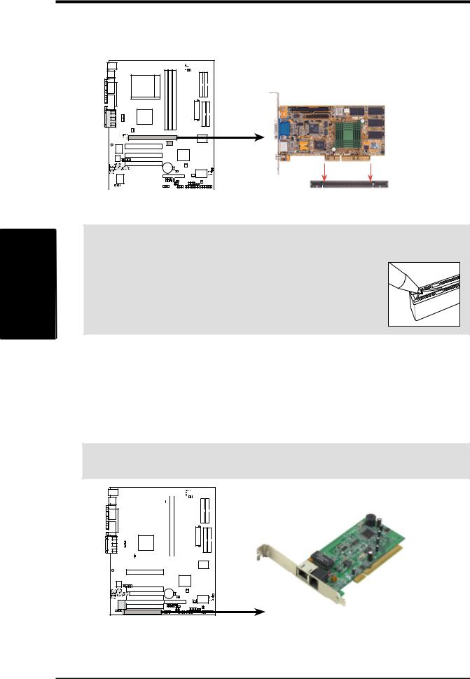
3Expansion
H/W .
SETUPCards
3.HARDWARE SETUP
3.7.3Accelerated Graphics Port (AGP) Pro Slot
This motherboard has an Accelerated Graphics Port (AGP) Pro slot to support the new generation graphics cards with ultra-high memory bandwidth.
|
|
|
|
|
|
|
|
|
|
|
|
|
|
|
|
|
|
|
|
|
|
|
|
|
|
|
|
|
|
|
|
|
|
|
|
|
1 |
0 |
01 |
01 |
|||||||
|
|
|
|
|
|
|
|
|
|
|
|
|
|
|
|
|
|
|
|
|
|
|
|
|
|
|
|
|
|
|
|
|
|
|
|
AGP Card without Retention Notch
A7V266-E
|
|
|
|
|
|
|
|
|
|
|
|
|
|
|
|
|
|
|
|
|
|
|
|
|
TOP VIEW |
|
|
|
|
|
|
|
|
|
|
|
|
|
|
|
|
|
|
|
|
|
|
|
|
|
|
|
|
|
|
|
|
|
|
|
|
|
|
|
|
|
|
|
|
|
|
|
|
|
|
|
|
|
|
|
|
|
|
|
|
|
|
|
|
|
|
|
|
|
|
|
|
|
|
|
|
|
|
A7V266-E Accelerated |
20-pin bay |
|
|
|
|
|
|
|
|
28-pin bay |
|||||||||||||||
Rib (inside slot) |
Rib |
||||||||||||||||||||||||
Graphics Port (AGP PRO) |
|
|
|
|
|
|
|
|
|
|
|||||||||||||||
CAUTION! The AGP Pro slot is shipped with a warning label over the 20-pin bay. DO NOT remove this label and the safety tab underneath it if you are using an AGP card without a retention notch. Removing may cause the
card to shift and may cause damage to the card, slot, and motherboard. Remove the label and tab ONLY if you are using an AGP Pro card. Use a rigid tip, such as a pen tip, to dislodge
Removing the tab
3.7.4 Advanced Communication Riser (ACR) Slot
This motherboard has an Advanced Communication Riser (ACR) slot for communications and audio subsystems. The slot supports modem, audio, LAN, and Home Phoneline Networking Alliance (HPNA) or Home Networking cards. The ACR slot is backward compatible with the Audio Modem Riser (AMR) cards.
IMPORTANT! The ACR slot on the motherboard shares the same expansion slot with PCI Slot 5.
|
|
|
|
|
|
|
|
|
|
|
|
|
|
|
|
|
|
|
|
|
|
|
|
|
|
|
|
|
|
|
|
|
|
|
|
|
|
|
|
|
|
|
|
|
|
|
|
|
|
|
|
|
|
|
|
|
|
|
|
|
|
|
|
|
|
|
|
01 |
1 |
0 |
0 |
|
|
|
|
|
|
|
|
|
|
|
|
|
|
|
|
|
|
|
|
|
|
|
|
|
|
|
|
|
|
|
|
|
|
|
|
|
|
|
|
|
|
|
|
|
|
|
|
|
|
|
|
|
|
|
|
|
|
|
|
|
|
|
|
|
|
|
|
|
|
|
|
|
|
|
|
|
|
|
|
|
|
|
|
|
|
|
|
|
|
|
|
|
|
|
|
|
|
|
|
|
|
|
|
|
|
|
|
|
|
|
|
|
|
|
|
|
|
|
|
|
|
|
|
|
|
|
|
|
|
|
|
|
|
|
|
|
|
|
|
|
|
|
|
|
|
|
|
|
|
|
|
|
|
|
|
|
|
|
|
|
|
|
|
|
|
|
|
|
|
|
|
|
|
|
|
|
|
|
|
|
|
|
|
|
|
|
|
|
|
|
|
|
|
|
|
|
|
|
|
|
|
|
|
|
|
|
|
|
|
|
|
|
|
|
|
|
|
|
|
|
|
|
|
|
|
|
|
|
|
|
|
|
|
A7V266-E
A7V266-E Advanced
Communication Riser (ACR)
30 |
ASUS A7V266-E User’s Manual |
 Loading...