


 AP2400R-E2
Dual Intel® Xeon™ 2U Rackmount Server 800 MHz Front Side Bus
Service Guide

E1800
First edition V1
June 2005
Copyright © 2005 ASUSTeK COMPUTER INC. All Rights Reserved.
No part of this manual, including the products and software described in it, may be reproduced, transmitted, transcribed, stored in a retrieval system, or translated into any language in any form or by any means, except documentation kept by the purchaser for backup purposes, without the express written permission of ASUSTeK COMPUTER INC. (“ASUS”).
ASUS provides this manual “as is” without warranty of any kind, either express or implied, including but not limited to the implied warranties or conditions of merchantability or fitness for a particular purpose. In no event shall ASUS, its directors, officers, employees, or agents be liable for any indirect, special, incidental, or consequential damages (including damages for loss of profits, loss of business, loss of use or data, interruption of business and the like), even if ASUS has been advised of the possibility of such damages arising from any defect or error in this manual or product.
Specifications and information contained in this manual ae furnished for informational use only, and are subject to change at any time without notice, and should not be construed as a commitment by ASUS. ASUS assumes no responsibility or liability for any errors or inaccuracies that may appear in this manual, including the products and software described in it.
Product warranty or service will not be extended if: (1) the product is repaired, modified or altered, unless such repair, modification of alteration is authorized in writing by ASUS; or (2) the serial number of the product is defaced or missing.
Products and corporate names appearing in this manual may or may not be registered trademarks or copyrights of their respective companies, and are used only for identification or explanation and to the owners’ benefit, without intent to infringe.
i i

Contents
Notices ................................................................................................ |
vi |
Safety information ............................................................................. |
vii |
About this guide ............................................................................... |
viii |
Chapter 1: Product introduction
1.1 |
System package contents .................................................... |
1-2 |
|
1.2 |
System specifications .......................................................... |
1-3 |
|
1.2 |
System specifications .......................................................... |
1-4 |
|
1.3 |
Front panel features ............................................................. |
1-5 |
|
1.4 |
Rear panel features .............................................................. |
1-5 |
|
1.5 |
Internal features ................................................................... |
1-6 |
|
1.6 |
LED information .................................................................... |
1-7 |
|
|
1.6.1 |
Front panel LEDs .................................................... |
1-7 |
|
1.6.2 |
Rear fan LEDs ......................................................... |
1-8 |
|
1.6.3 |
System fan LED ...................................................... |
1-8 |
|
1.6.4 |
Power supply LED ................................................... |
1-9 |
|
1.6.5 |
LAN port LEDs ........................................................ |
1-9 |
Chapter 2: Hardware setup
2.1 |
Chassis cover ....................................................................... |
2-2 |
|
|
2.1.1 Removing the front bezel ....................................... |
2-2 |
|
|
2.1.2 Removing the top cover ......................................... |
2-3 |
|
|
2.1.3 Installing the top cover .......................................... |
2-5 |
|
|
2.1.4 Removing the air duct ............................................ |
2-6 |
|
|
2.1.5 Installing the air duct .............................................. |
2-6 |
|
2.2 |
Central Processing Unit (CPU) .............................................. |
2-8 |
|
|
2.2.1 Removing the CPU heatsink .................................... |
2-8 |
|
|
2.2.2 |
Installing a CPU ....................................................... |
2-9 |
|
2.2.3 Installing the CPU heatsink ................................... |
2-12 |
|
2.3 |
System memory ................................................................. |
2-13 |
|
|
2.3.1 |
Memory configurations ......................................... |
2-13 |
|
2.3.2 |
Installing a DIMM ................................................... |
2-14 |
|
2.3.3 |
Removing a DIMM ................................................. |
2-14 |
2.4 |
Hard disk drives .................................................................. |
2-15 |
|
2.5 |
Expansion cards .................................................................. |
2-17 |
|
|
2.5.1 Installing a low-profile expansion card .................. |
2-17 |
|
|
2.5.2 Installing a full-length expansion card .................. |
2-18 |
|
|
2.5.3 |
ZCR socket ........................................................... |
2-21 |
|
2.5.4 Configuring an expansion card.............................. |
2-22 |
|
i i i

Contents
2.6 |
Cable connections .............................................................. |
2-23 |
|
|
2.6.1 |
Motherboard ......................................................... |
2-24 |
|
2.6.2 |
SCSI backplanes .................................................... |
2-25 |
|
2.6.3 |
SCSI HDD configurations....................................... |
2-26 |
|
2.6.4 |
SCSI ID assignments ............................................. |
2-29 |
|
2.6.5 |
SCSI jumper settings ............................................ |
2-29 |
|
2.6.6 SMBus and backplane power cabling .................... |
2-30 |
|
|
2.6.7 |
Fan boards ............................................................ |
2-31 |
2.7 |
Removable components ..................................................... |
2-33 |
|
|
2.7.1 |
Hot-swap mid-fans (80mm) ................................. |
2-33 |
|
2.7.2 |
Rear fans (60mm) ................................................ |
2-34 |
|
2.7.3 |
Power supply modules .......................................... |
2-34 |
|
2.7.4 Slim optical and floppy drives ............................... |
2-35 |
|
|
2.7.5 Front panel LED and switch board ........................ |
2-36 |
|
|
2.7.6 |
SCSI backplanes .................................................... |
2-36 |
Chapter 3: Installation options |
|
|
3.1 |
Rackmount rail kit items ....................................................... |
3-2 |
3.2 |
Attaching the rails to the server .......................................... |
3-3 |
3.3 |
Attaching the rack rails ........................................................ |
3-4 |
3.4 |
Rackmounting the server ..................................................... |
3-6 |
Chapter 4: Motherboard info |
|
|
4.1 |
Motherboard layout .............................................................. |
4-2 |
4.2 |
Jumpers ................................................................................ |
4-4 |
4.3 |
Connectors ........................................................................... |
4-9 |
Chapter 5: |
BIOS information |
|
5.1 Managing and updating your BIOS ........................................ |
5-2 |
|
5.1.1 Creating a bootable floppy disk .............................. |
5-2 |
|
5.1.2 |
AFUDOS utility ........................................................ |
5-3 |
5.1.3 ASUS CrashFree BIOS 2 utility ................................ |
5-6 |
|
5.1.4 |
ASUS Update utility ................................................ |
5-8 |
5.2 BIOS setup program ........................................................... |
5-11 |
|
5.2.1 |
BIOS menu screen................................................. |
5-12 |
5.2.2 |
Menu bar ............................................................... |
5-12 |
5.2.3 |
Navigation keys .................................................... |
5-12 |
5.2.4 |
Menu items ........................................................... |
5-13 |
5.2.5 |
Sub-menu items ................................................... |
5-13 |
i v

Contents
|
5.2.6 |
Configuration fields .............................................. |
5-13 |
|
5.2.7 |
Pop-up window ..................................................... |
5-13 |
|
5.2.8 |
Scroll bar .............................................................. |
5-13 |
|
5.2.9 |
General help .......................................................... |
5-13 |
5.3 |
Main menu .......................................................................... |
5-14 |
|
|
5.3.1 |
System Time......................................................... |
5-14 |
|
5.3.2 |
System Date ......................................................... |
5-14 |
|
5.3.3 |
Legacy Diskette A ................................................ |
5-14 |
|
5.3.4 |
Primary/Secondary IDE Master/Slave, |
|
|
|
Third and Fourth IDE/SATA .................................. |
5-15 |
|
5.3.5 |
IDE Configuration .................................................. |
5-17 |
|
5.3.6 |
System Information .............................................. |
5-18 |
5.4 |
Advanced menu .................................................................. |
5-19 |
|
|
5.4.1 |
USB Configuration................................................. |
5-19 |
|
5.4.2 |
MPS Configuration ................................................ |
5-21 |
|
5.4.3 |
Remote Access Configuration .............................. |
5-22 |
|
5.4.4 |
CPU Configuration................................................. |
5-24 |
|
5.4.5 |
Chipset ................................................................. |
5-25 |
|
5.4.6 |
Onboard Devices Configuration ............................ |
5-27 |
|
5.4.7 |
PCI PnP ................................................................. |
5-28 |
5.5 |
Power menu ........................................................................ |
5-30 |
|
|
5.5.1 |
ACPI APIC Support ................................................ |
5-30 |
|
5.5.2 |
APM Configuration ................................................ |
5-30 |
|
5.5.3 |
Hardware Monitor ................................................. |
5-33 |
5.6 |
Boot menu .......................................................................... |
5-35 |
|
|
5.6.1 |
Boot Device Priority .............................................. |
5-35 |
|
5.6.2 |
Boot Settings Configuration ................................. |
5-36 |
|
5.6.3 |
Security ................................................................ |
5-37 |
5.7 |
Exit menu ........................................................................... |
5-40 |
|
Appendix: |
References |
|
|
A.1 |
Power supply ........................................................................ |
A-2 |
|
|
A.1.1 |
General description ................................................. |
A-2 |
|
A.1.2 |
Specifications ......................................................... |
A-3 |
A.2 |
Qualified Vendors List (QVL) ............................................... |
A-4 |
|
A.3 |
Troubleshooting ................................................................... |
A-6 |
|
A.4 |
NCL-DS1R2 block diagram.................................................... |
A-8 |
|
v

Notices
Federal Communications Commission Statement
This device complies with Part 15 of the FCC Rules. Operation is subject to the following two conditions:
•This device may not cause harmful interference, and
•This device must accept any interference received including interference that may cause undesired operation.
This equipment has been tested and found to comply with the limits for a Class B digital device, pursuant to Part 15 of the FCC Rules. These limits are designed to provide reasonable protection against harmful interference in a residential installation. This equipment generates, uses and can radiate radio frequency energy and, if not installed and used in accordance with manufacturer’s instructions, may cause harmful interference to radio communications. However, there is no guarantee that interference will not occur in a particular installation. If this equipment does cause harmful interference to radio or television reception, which can be determined by turning the equipment off and on, the user is encouraged to try to correct the interference by one or more of the following measures:
•Reorient or relocate the receiving antenna.
•Increase the separation between the equipment and receiver.
•Connect the equipment to an outlet on a circuit different from that to which the receiver is connected.
•Consult the dealer or an experienced radio/TV technician for help.
WARNING! The use of shielded cables for connection of the monitor to the graphics card is required to assure compliance with FCC regulations. Changes or modifications to this unit not expressly approved by the party responsible for compliance could void the user’s authority to operate this equipment.
Canadian Department of Communications Statement
This digital apparatus does not exceed the Class B limits for radio noise emissions from digital apparatus set out in the Radio Interference Regulations of the Canadian Department of Communications.
This class B digital apparatus complies with Canadian ICES-003.
v i

Safety information
Electrical safety
•Before installing or removing signal cables, ensure that the power cables for the system unit and all attached devices are unplugged.
•To prevent electrical shock hazard, disconnect the power cable from the electrical outlet before relocating the system.
•When adding or removing any additional devices to or from the system, ensure that the power cables for the devices are unplugged before the signal cables are connected. If possible, disconnect all power cables from the existing system before you add a device.
•If the power supply is broken, do not try to fix it by yourself. Contact a qualified service technician or your dealer.
Operation safety
•Any mechanical operation on this server must be conducted by certified or experienced engineers.
•Before operating the server, carefully read all the manuals included with the server package.
•Before using the server, make sure all cables are correctly connected and the power cables are not damaged. If any damage is detected, contact your dealer as soon as possible.
•To avoid short circuits, keep paper clips, screws, and staples away from connectors, slots, sockets and circuitry.
•Avoid dust, humidity, and temperature extremes. Place the server on a stable surface.
This product is equipped with a three-wire power cable and plug for the user’s safety. Use the power cable with a properly grounded electrical outlet to avoid electrical shock.
Lithium-Ion Battery Warning  CAUTION! Danger of explosion if battery is incorrectly replaced. Replace only with the same or equivalent type recommended by the manufacturer. Dispose of used batteries according to the manufacturer’s instructions.
 CD-ROM Drive Safety Warning
CLASS 1 LASER PRODUCT
Heavy System
CAUTION! This server system is heavy. Ask for assistance when moving or carrying the system.
v i i

About this guide
Audience
This user guide is intended for system integrators and experienced users with at least basic knowledge of configuring a server.
Contents
This guide contains the following parts:
1 . Chapter 1: Product Introduction
This chapter describes the general features of the barebone server, including sections on the front panel and rear panel specifications.
2 . Chapter 2: Hardware setup
This chapter lists the hardware setup procedures that you have to perform when installing or removing system components.
3 . Chapter 3: Installation options
This chapter describes how to prepare the barebone server for rack mounting.
4 . Chapter 4: Motherboard information
This chapter gives information about the motherboard that comes with the server. This chapter includes the motherboard layout, jumper settings, and connector locations.
5 . Chapter 5: BIOS information
This chapter tells how to change the system settings through the BIOS Setup menus. Detailed descriptions of the BIOS parameters are also provided.
7 . Appendix: References
This appendix includes additional information that you may refer to when configuring your barebone server.
viii
Conventions
To make sure that you perform certain tasks properly, take note of the following symbols used throughout this manual.
WARNING: Information to prevent injury to yourself when trying to complete a task.
CAUTION: Information to prevent damage to the components when trying to complete a task.
IMPORTANT: Instructions that you MUST follow to complete a task.
NOTE: Tips and information to aid in completing a task.
Reference
Visit the ASUS websites worldwide that provide updated information for all ASUS hardware and software products. Refer to the ASUS contact information for details.
i x

x
Chapter 1
This chapter describes the general features of the barebone server, including sections on the front panel and rear panel specifications.
ASUS AP2400R-E2
Product introduction
1-1
1.1System package contents
Check your system package for the following items.
Chassis |
ASUS AR21 2U rackmount chassis |
|
|
Motherboard |
ASUS NCL-DS1R2 motherboard |
|
|
Components |
700W redundant power supply, 115V~230V |
|
Slim optical drive| |
|
Slim floppy disk drive |
|
Chassis fan |
|
HDD fan |
|
Hot-swap SCSI HDD trays |
|
SCSI backplanes |
|
Front bezel |
|
CPU heatsink (2 pcs.) |
|
|
Cables |
RJ-45 extension connector |
|
AC power cable |
|
System cables |
|
|
Accessories |
Rackmount rail kit |
|
AP2400R-E2 user guide |
|
AP2400R-E2 support CD (includes ASWM*) |
|
CA eTrust Anti-virus CD |
|
AR21 chassis ears (left, right) |
|
Thermal grease strip |
|
Bag of screws |
|
|
*ASUS System Web-based Management
If any of the above items is damaged or missing, contact your retailer.
1 - 2 |
Chapter 1: Product introduction |
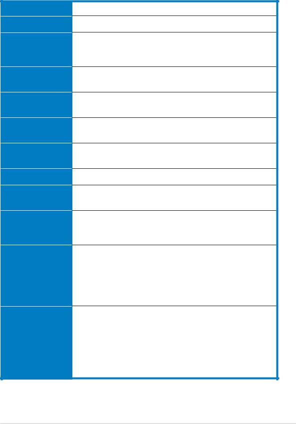
1.2System specifications
The ASUS AP2400R-E2 is a 2U barebone server system featuring the ASUS NCL-DS1R2 motherboard. The server supports dual Intel® Xeon™ processors with EM64T technology, plus other latest technologies through the chipsets onboard.
Chassis
Motherboard
Chipset
C P U
Memory
L A N
V G A
SCSI
Expansion slots
Storage
Front panel
Rear panel
Rackmount 2U (AR21)
ASUS NCL-DS1R2
North Bridge: Intel® E7520 MCH
South Bridge: Intel® 82801ER
I/O Bridge: Intel® 6700PXH Bridge
Supports dual Intel® Xeon™ 3.6 GHz processors with L2 1 MB and 2 MB caches via two 604-pin sockets
8 x 184-pin DDR sockets for up to 16 GB system memory Supports PC2700 registered ECC DDR DIMMs
2 x Broadcom® BCM5721 PCI Express Gigabit LAN controllers
ATI RAGE-XL PCI-based VGA controller
Supports 8MB display memory
Adaptec® AIC-7902W Ultra320 Dual-channel SCSI controller
3 x full-length 64-bit/66MHz 3V PCI-X slots (on a riser card) 1 x low-profile 64-bit/133MHz 3V PCI-X slot
8 x 3.5-inch hot-swappable HDD bays 1 x slim optical drive
1 x slim 1.44MB floppy drive
2 x USB 2.0 ports Power switch Reset switch Location switch
Power, HDD access, location, message, LAN HDD LEDs: Status, activity
1 x PS/2 keyboard port
1 x PS/2 mouse port
1 x Serial port
1 x VGA port
2 x USB 2.0 ports
2 x RJ-45 ports (with LEDs)
1 x external SCSI port (alternative)
(continued on the next page)
ASUS AP2400R-E2 |
1 - 3 |

1.2System specifications
|
Management |
|
ASUS Server Web-based Management (ASWM) |
|
Hardware |
|
|
|
|
Voltage, temperature, and fan speed monitoring |
|
|
monitors |
|
Automatic System Restart (ASR) feature |
|
Power supply |
|
|
|
|
700W redundant power supply, 115V~230V, 50Hz~60Hz |
|
|
Dimensions |
|
|
|
|
732.5mm (l) x 448mm (w) x 87.7mm (h) |
|
|
|
|
|
Refer to “Chapter 4 Motherboard information” for details on the internal connectors.
1 - 4 |
Chapter 1: Product introduction |
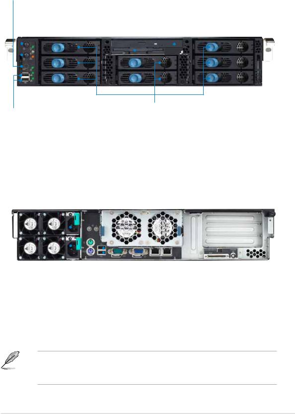
1.3Front panel features
The barebone server displays a simple yet stylish front panel with easily accessible features. The power and reset buttons, LED indicators, location switch, slim optical and floppy drives, and two USB ports are located on the front panel.
Rese t button
Location switch
Powe r button |
Slim floppy drive |
Slim optical drive |
||||||
|
|
|
|
|||||
|
|
|
|
|
|
|
|
|
|
|
|
|
|
|
|
|
|
|
|
|
|
|
|
|
|
|
|
|
|
|
|
|
|
|
|
|
|
|
|
|
|
|
|
|
|
|
|
|
|
|
|
|
|
|
|
|
|
|
|
|
|
|
Front panel LEDs
Hot-swappable HDD bays
USB 2.0 ports
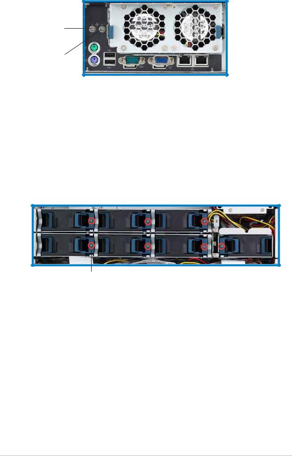
1.4Rear panel features
The rear panel includes the expansion slots, LAN, VGA, and I/O ports, fans, and the system power sockets.
Redundant power |
|
Rea r fans |
|
|
|
|
|
|
|
|
|
||||||||||
supply modules |
|
statu s LEDs |
Rea r fans |
|
Expansion slots |
||||||||||||||||
|
|
|
|
|
|
|
|
|
|
|
|
|
|
|
|
|
|
|
|
|
|
|
|
|
|
|
|
|
|
|
|
|
|
|
|
|
|
|
|
|
|
|
|
|
|
|
|
|
|
|
|
|
|
|
|
|
|
|
|
|
|
|
|
|
|
|
|
|
|
|
|
|
|
|
|
|
|
|
|
|
|
|
|
|
|
|
|
|
|
|
|
|
|
|
|
|
|
|
|
|
|
|
|
|
|
|
|
|
|
|
|
|
|
|
|
|
|
|
|
|
|
|
|
|
|
|
|
|
|
|
|
|
|
|
|
|
|
|
|
|
|
|
|
|
|
|
|
|
|
|
|
|
|
|
|
|
|
|
|
|
|
|
|
|
|
|
|
|
|
|
|
|
|
|
|
|
|
|
|
|
|
|
|
|
|
|
|
|
|
|
|
|
|
|
|
|
|
|
|
|
|
|
|
|
|
|
|
|
|
|
|
|
|
|
|
|
|
|
|
|
|
|
|
|
|
|
|
|
|
|
|
|
|
|
|
|
|
|
|
|
|
s t e k c o s r e w o p C A
S PS P 2 /2 /
e ko m b yu oe s r ap do
pt r r o
t
s t r o p 0 . 2 B S U
Ser ia l |
VGA p |
Gig ab i |
Gig ab i |
p |
o |
t |
t |
ort |
rt |
LA N |
LA N |
|
|
1 |
2 |
|
|
po rt |
po rt |
lanretxE tla( trop |
noitacoL |
noitacoL |
ISCS itanre |
ctiws |
DEL |
v |
h |
|
)e |
|
|
When disconnecting LAN cables, you need to remove the rear fan cage. Refer to section “2.7 Removable components” for instructions on removing the fan cage.
ASUS AP2400R-E2 |
1 - 5 |
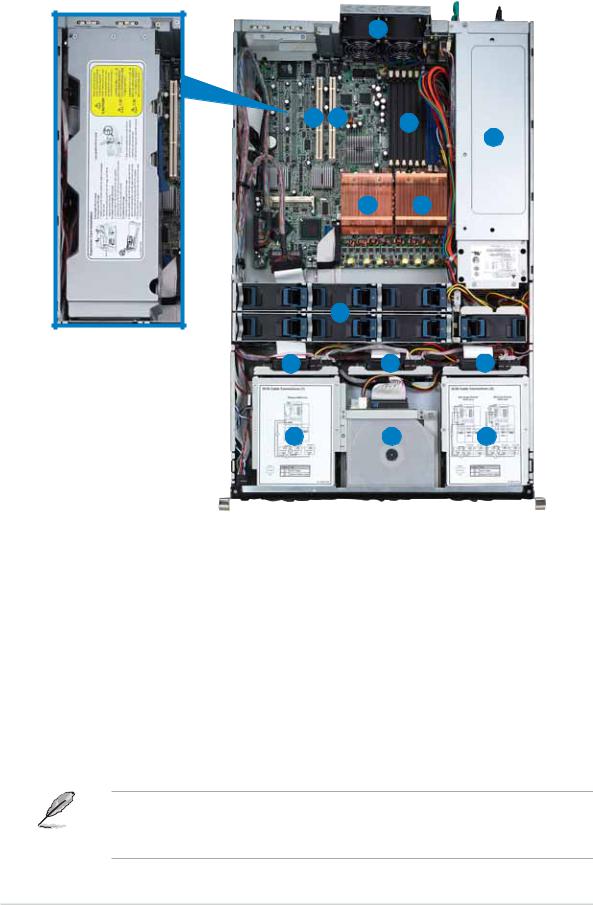
1.5Internal features
The barebone system includes the basic components as shown.
1
2 |
3 |
4 |
|
|
5
6 7
8
PCI-X card cage
9 |
10 |
11 |
12 |
13 |
14 |
1.2 x rear fans
2.64-bit PCI-X slots
(underneath the PCI-X card cage)
3.Low profile PCI-X slot
4.8 x DDR DIMM sockets
5.Power supply cage
6.CPU2 socket with heatsink
7.CPU1 socket with heatsink
8.7 x system fans
9.SCSI backplane 1
10.SCSI backplane 2
11.SCSI backplane 3
12.3 x HDD bays
13.Top: Slim optical drive Mid: Slim floppy drive Bottom: 2 x HDD bays
14.3 x HDD bays
The air duct lies on top of the motherboard components. Remove the air duct to access the components. Refer to section “2.1.4 Removing and installing the air duct” for instructions.
1 - 6 |
Chapter 1: Product introduction |
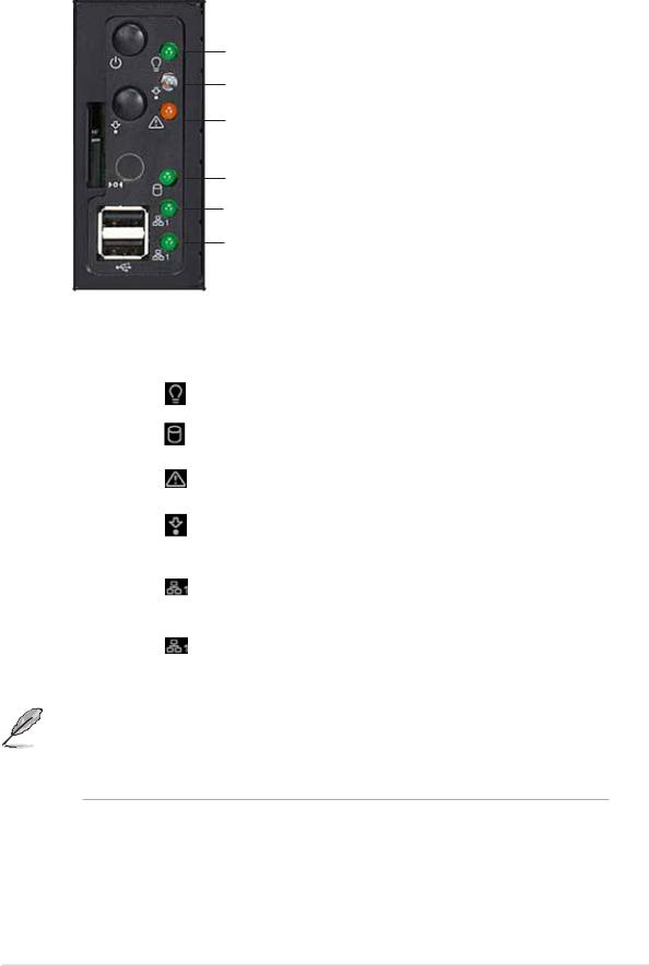
1.6LED information
1.6.1Front panel LEDs
Powe r LED
Locatio n LED
Messag e LED
Storage Access LED
LAN 1 LED
LAN 2 LED
L E D |
I c o n |
Display status |
Description |
|
|
|
|
|
|
|
|
Power LED |
|
ON |
System power ON |
|
|
|
|
|
|
|
|
Storage Access LED |
|
OFF |
No activity |
|
|
|
|
|
Blinking |
Read/write data into the HDD |
|
|
|
|
|
|
|
Message LED |
|
OFF |
System is normal; no incoming event |
|
|
|
|
|
Blinking |
ASWM indicates a HW monitor event |
|
|
|
|
|
|
|
Location LED |
|
OFF |
Normal status |
|
|
|
|
|
ON |
Location switch is pressed |
|
|
|
|
|
(Press the location switch again to turn off) |
|
|
|
|
|
|
|
LAN1 LED |
|
OFF |
No 64-bit Gbit LAN connection |
|
|
|
|
|
Blinking |
LAN is transmitting or receiving data |
|
|
|
|
ON |
LAN connection is present |
|
|
|
|
|
|
|
LAN2 LED |
|
OFF |
No 64-bit Gbit LAN connection |
|
|
|
|
|
Blinking |
LAN is transmitting or receiving data |
|
|
|
|
ON |
LAN connection is present |
|
|
|
|
|
|
|
|
|
|
|
|
|
The location switch and LED are for service purposes. When the system fails or is shut down, the server administrator can press either the front or the rear location switch to identify the location of the specific 2U system in a rack cabinet.
ASUS AP2400R-E2 |
1 - 7 |
1.6.2Rear fan LEDs
LED 1 for
Rea r Fa n 1
LED 2 for
Rea r Fa n 2
|
L E D |
Color |
Description |
|
|
|
|
|
LED1 |
Green |
Rear Fan 1 is in normal operation |
|
|
Orange |
Rear Fan 1 is faulty |
|
|
|
|
|
LED2 |
Green |
Rear Fan 2 is in normal operation |
|
|
Orange |
Rear Fan 2 is faulty |
|
|
|
|
1.6.3System fan LED
Each system fan has an LED to indicate the fan status.
L E D
L E D |
C o l o r |
Description |
|
|
|
LED |
Green |
Fan is in normal operation |
|
Orange |
Fan is faulty |
|
|
|
1 - 8 |
Chapter 1: Product introduction |

1.6.4Power supply LED
Each system fan has an LED to indicate the fan status.
L E D
L E D |
C o l o r |
Display status |
Description |
|
|
|
|
LED |
Green |
Blinking |
Power off and in standby mode |
|
|
|
|
|
Green |
On |
The power supply module is in normal operation |
|
|
|
|
|
Orange |
On |
One of the two power modules is disconnected |
|
|
|
from the power outlet or is defective |
|
|
|
|
|
Off |
Off |
Both power supply modules are disconnected |
|
|
|
from the power outlet or are defective |
|
|
|
|
1.6.5LAN port LEDs
|
|
|
|
|
|
|
|
|
SPEE D LED |
|
|
|
|
|
|
|
|
|
|
||
|
|
|
|
|
|
|
|
|
ACT/LIN K LED |
|
|
|
|
|
|
|
|
|
|
||
|
|
|
|
|
|
|
|
|
|
|
|
|
|
|
|
|
|||||
ACT/LIN K LED |
|
|
|
SPEE D LED |
|
|||||
|
|
|
|
|
|
|
||||
Status |
Description |
Status |
|
|
Description |
|
||||
OFF |
No link |
OFF |
|
10 Mbps connection |
|
|||||
|
|
|
|
|
|
|||||
GREEN |
Linked |
ORANGE |
|
100 Mbps connection |
|
|||||
|
|
|
|
|
|
|||||
BLINKING |
Data activity |
GREEN |
|
1 Gbps connection |
|
|||||
|
|
|
|
|
|
|
|
|
|
|
ASUS AP2400R-E2 |
1 - 9 |

1 - 10 |
Chapter 1: Product introduction |
Chapter 2
This chapter lists the hardware setup procedures that you have to perform when installing or removing system components.
ASUS AP2400R-E2
Hardware setup
1-1
2.1Chassis cover
The chassis features a “screwless design” that allows convenient assembly and disassembly.
•Remove the front bezel to access the hot-swap HDDs, optical drive, and floppy drive.
•Remove the chassis cover to access the internal components or if you want to install system devices.
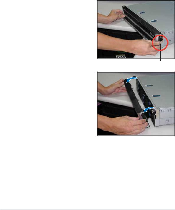
2.1.1Removing the front bezel
To remove the front bezel:
1.Hold the sides of the front bezel, then slightly press the middle part to disengage it from the front panel.
Press here to release
2.Pull the bezel from the front
panel.
2 - 2 |
Chapter 2: Hardware setup |
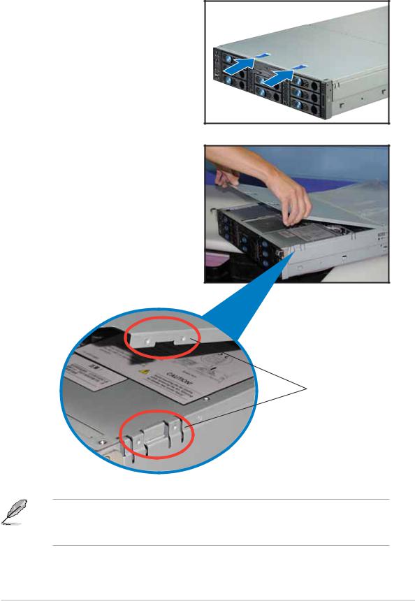
2.1.2Removing the top cover
Front half
To remove the front half of the top cover:
1.Push the two sliding locks on the top cover to release.
2.With both hands, flip up the front corners of the top cover, then lift.
The front corners of the cover have dents that match those on the chassis. These dents provide a holding mechanism and keeps the cover in place even when the sliding locks are released.
Matching d e n t s
If you wish to access the hot-swappable system fans, backplanes, optical drive, and floppy drive, you only need to remove the front half of the top cover.
ASUS AP2400R-E2 |
2 - 3 |
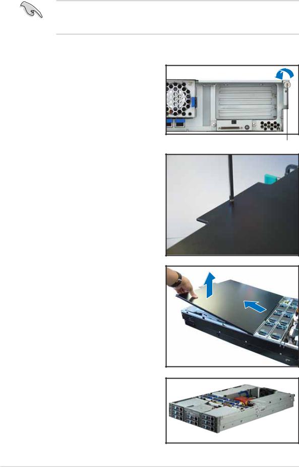
Rear half
You need to remove the front half of the top cover before you can remove the rear half of the top cover. Refer to section “2.1.1 Removing the top cover (front half)” for instructions.
To remove the rear half of the top cover:
1.Loosen the thumbscrew that secures the top cover on the rear part of the chassis.
Thumbscrew
2.Remove the screw on the rear half of the cover.
3.Firmly hold the rear half of the top cover, then remove it from the chassis.
The barebone server without the top cover is shown on the right.
2 - 4 |
Chapter 2: Hardware setup |

2.1.3Installing the top cover
To install the top cover:
1.Place the rear half of the top cover over the chassis as shown, and align the mid-hooks with the notches on the sides.
2.Slide the cover toward the front panel until the mid-hooks are locked into the notches.
3.Flip down the front half part of the top cover.
4.Push the sliding locks toward the front edge to secure the front half of the top cover in place.
5.Tighten the thumbscrew on the rear corner of the cover to completely secure the top cover.
Thumbscrew
6.Replace the screw on the rear half of the cover.
ASUS AP2400R-E2 |
2 - 5 |
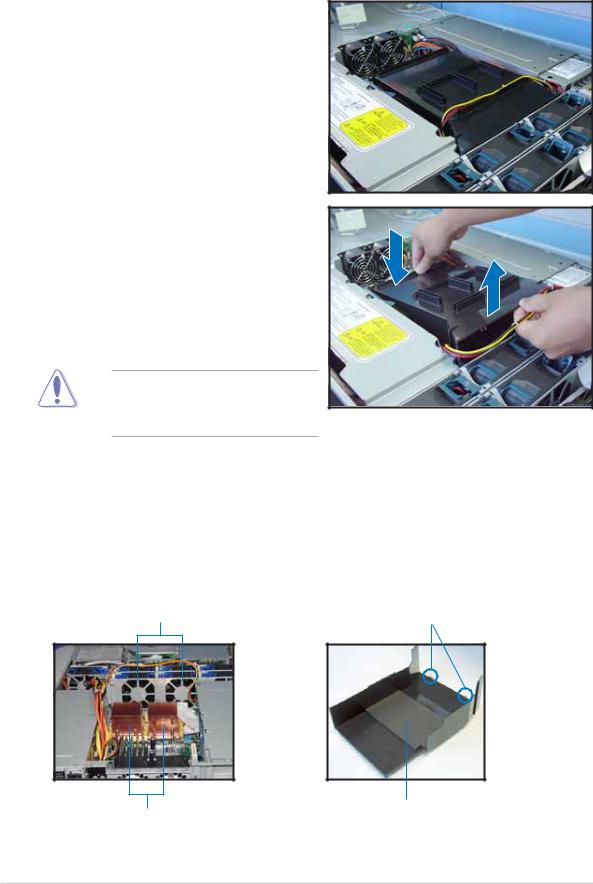
2.1.4Removing the air duct
To remove the air duct:
1.Carefully route the cables that may interfere when removing the air duct.
2.Hold the rear part of the air duct and press it for about a fraction of an inch, just enough to tilt the front end.
3.When tilted, carefully pull the air duct upward to release it from the chassis.
Be careful not to pull off or break any cables while removing the air duct.
2.1.5Installing the air duct
To install the air duct:
1.Take note of the parts of the air duct that should match specific locations inside the chassis.
Metal strips to fit the plastic clips on the air duct
Plastic clips to grip the metal strips on the fan cage
CPU heatsinks |
Flat rubber pad should match |
|
the top of the two heatsinks |
2 - 6 |
Chapter 2: Hardware setup |
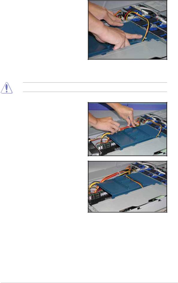
2.Position the air duct inside the chassis with the plastic clips matching the two vertical metal strips on the fan cage.
3.Check the rubber pads underneath the air duct and ensure that they are in place; otherwise, the air duct will not fit properly.
4.Fit the other end of the air duct making sure that no power cable is strayed under it.
Be careful not to pull off or break any cables while installing the air duct.
5.When the air duct is in place, arrange the power cable cluster to fit the space beside the air duct.
6.Flatten the power cable that runs across the air duct. When properly installed, the air duct should appear as shown.
ASUS AP2400R-E2 |
2 - 7 |
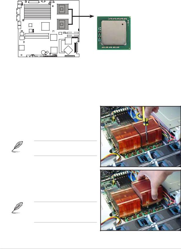
2.2Central Processing Unit (CPU)
The motherboard comes with two surface mount 604-pin Zero Insertion Force (ZIF) socket and designed for the Intel® Xeon™ processors.
Note in the illustration that the CPU has a gold triangular mark on one corner. This mark indicates the processor Pin 1 that should match a specific corner of the CPU socket.
Intel Xeon
NCL-DS1R2 |
 Gold Arrow
Pin A1
NCL-DS1R2 CPU Socket 604
2.2.1Removing the CPU heatsink
You must remove the CPU heatsink(s) before installing the CPU(s).
To remove the CPU heatsink:
1.Use a Phillips (cross) screwdriver to loosen the four screws that secure the heatsink until it is released.
You don’t need to detach the screws from the heatsink.
2.Carefully lift the heatsink from the motherboard.
3.Remove the rubber pad(s) on top of the CPU socket(s).
Remove the rubber pad(s) only when you are ready to install the CPU(s).
2 - 8 |
Chapter 2: Hardware setup |

4.Remove the rubber pad(s) on top of the CPU socket(s).
Remove the rubber pad(s) only when you are ready to install the CPU(s).
2.2.2Installing a CPU
• The motherboard supports either one or two CPUs. If you are installing only one CPU, you MUST install it in CPU socket 1.
•If you are installing two CPUs, install in the CPU socket 2 first.
CP U Socke t 1 (outer socket)
CP U Socke t 2 (inner socket with rubber pad)
Incorrect installation of the CPU into the socket may bend the pins and severely damage the CPU!
To install the CPUs:
1.Locate the CPU1 socket on the motherboard. Flip up the socket lever and push it all the way to the other side.
Make sure that the socket lever is pushed back all the way. Otherwise the CPU does not fit in completely.
ASUS AP2400R-E2 |
2 - 9 |
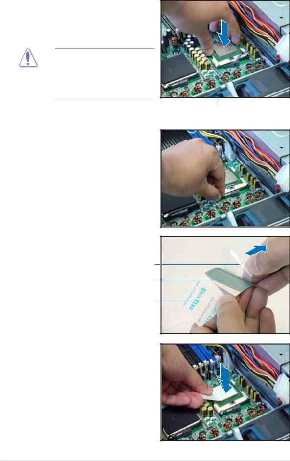
2.Position the CPU above the socket as shown.
3.Carefully insert the CPU into the socket until it fits in place.
The CPU fits only in one correct orientation. DO NOT force the CPU into the socket to prevent bending the pins and damaging the CPU!
4.Carefully push down the socket lever to secure the CPU. The lever clicks on the side tab to indicate that it is locked.
5.Peel off the plastic film of the thermal grease strip.
Plasti c film
Thermal grease
Thermal grease strip
6.Place the thermal grease strip on top of the installed CPU. Make sure that the thermal grease covers the entire surface of the CPU.
Marked corner
2 - 10 |
Chapter 2: Hardware setup |
 Loading...