


 Loading...
A8NE-FM
Motherboard

E1834
First Edition V1
November 2004
Copyright © 2004 ASUSTeK COMPUTER INC. All Rights Reserved.
No part of this manual, including the products and software described in it, may be reproduced, transmitted, transcribed, stored in a retrieval system, or translated into any language in any form or by any means, except documentation kept by the purchaser for backup purposes, without the express written permission of ASUSTeK COMPUTER INC. (“ASUS”).
Product warranty or service will not be extended if: (1) the product is repaired, modified or altered, unless such repair, modification of alteration is authorized in writing by ASUS; or (2) the serial number of the product is defaced or missing.
ASUS PROVIDES THIS MANUAL “AS IS” WITHOUT WARRANTY OF ANY KIND, EITHER EXPRESS OR IMPLIED, INCLUDING BUT NOT LIMITED TO THE IMPLIED WARRANTIES OR CONDITIONS OF MERCHANTABILITY OR FITNESS FOR A PARTICULAR PURPOSE. IN NO EVENT SHALL ASUS, ITS DIRECTORS, OFFICERS, EMPLOYEES OR AGENTS BE LIABLE FOR ANY INDIRECT, SPECIAL, INCIDENTAL, OR CONSEQUENTIAL DAMAGES (INCLUDING DAMAGES FOR LOSS OF PROFITS, LOSS OF BUSINESS, LOSS OF USE OR DATA, INTERRUPTION OF BUSINESS AND THE LIKE), EVEN IF ASUS HAS BEEN ADVISED OF THE POSSIBILITY OF SUCH DAMAGES ARISING FROM ANY DEFECT OR ERROR IN THIS MANUAL OR PRODUCT.
SPECIFICATIONS AND INFORMATION CONTAINED IN THIS MANUAL ARE FURNISHED FOR INFORMATIONAL USE ONLY, AND ARE SUBJECT TO CHANGE AT ANY TIME WITHOUT NOTICE, AND SHOULD NOT BE CONSTRUED AS A COMMITMENT BY ASUS. ASUS ASSUMES NO RESPONSIBILITY OR LIABILITY FOR ANY ERRORS OR INACCURACIES THAT MAY APPEAR IN THIS MANUAL, INCLUDING THE PRODUCTS AND SOFTWARE DESCRIBED IN IT.
Products and corporate names appearing in this manual may or may not be registered trademarks or copyrights of their respective companies, and are used only for identification or explanation and to the owners’ benefit, without intent to infringe.
i i

Contents
Notices ................................................................................................. |
v |
Safety information .............................................................................. |
vi |
A8NE-FM specifications summary ...................................................... |
vii |
Chapter 1: |
Hardware information |
|
|
1.1 |
Before you proceed .............................................................. |
1-2 |
|
1.2 |
Motherboard overview .......................................................... |
1-3 |
|
|
1.2.1 |
Placement direction ................................................ |
1-3 |
|
1.2.2 |
Screw holes ............................................................ |
1-3 |
|
1.2.3 |
Motherboard layout ................................................ |
1-4 |
|
1.2.4 |
Layout contents ..................................................... |
1-5 |
1.3 |
Central Processing Unit (CPU) .............................................. |
1-7 |
|
|
1.3.1 |
Installing the CPU.................................................... |
1-7 |
|
1.3.2 Installing the heatsink and fan ................................ |
1-9 |
|
1.4 |
System memory ................................................................. |
1-12 |
|
|
1.4.1 |
Overview ............................................................... |
1-12 |
|
1.4.2 |
Memory configurations ......................................... |
1-12 |
|
1.4.3 |
Installing a DIMM ................................................... |
1-13 |
|
1.4.4 |
Removing a DIMM ................................................. |
1-13 |
1.5 |
Expansion slots ................................................................... |
1-14 |
|
|
1.5.1 Installing an expansion card .................................. |
1-14 |
|
|
1.5.2 Configuring an expansion card.............................. |
1-14 |
|
|
1.5.4 PCI Express x16 slot ............................................. |
1-16 |
|
|
1.5.3 |
PCI slots ................................................................ |
1-16 |
1.6 |
Jumpers |
.............................................................................. |
1-17 |
1.7 |
Connectors ......................................................................... |
1-20 |
|
|
1.7.1 |
Rear panel connectors .......................................... |
1-20 |
|
1.7.2 |
Internal connectors............................................... |
1-22 |
i i i

Contents
Chapter 2: |
BIOS setup |
|
|
2.1 |
Managing and updating your BIOS ........................................ |
2-2 |
|
|
2.1.1 Creating a bootable floppy disk .............................. |
2-2 |
|
|
2.1.2 |
AwardBIOS Flash Utility .......................................... |
2-3 |
|
2.1.3 ASUS CrashFree BIOS 2 utility ................................ |
2-7 |
|
2.2 |
BIOS Setup program ............................................................. |
2-8 |
|
|
2.2.1 |
BIOS menu bar ........................................................ |
2-9 |
|
2.2.2 |
Legend bar ............................................................. |
2-9 |
2.3 |
Main Menu........................................................................... |
2-11 |
|
|
2.3.1 |
System Time......................................................... |
2-11 |
|
2.3.2 |
System Date ......................................................... |
2-11 |
|
2.3.3 |
Legacy Diskette A ................................................ |
2-11 |
|
2.3.4 |
Installed Memory .................................................. |
2-11 |
|
2.3.5 Primary and Secondary IDE Master/Slave ............. |
2-12 |
|
|
2.3.6 First, Second, Third, and Fourth SATA Master ..... |
2-14 |
|
2.4 |
Advanced Menu .................................................................. |
2-15 |
|
|
2.4.1 |
CPU configuration ................................................. |
2-16 |
|
2.4.2 |
Chipset configuration ........................................... |
2-17 |
|
2.4.3 |
PCIPnP ................................................................... |
2-19 |
|
2.4.4 |
Onboard device configuration ............................. |
2-20 |
2.5 |
Power Menu ........................................................................ |
2-25 |
|
|
2.5.1 |
APM configuration ................................................ |
2-26 |
|
2.5.2 |
Hardware monitor ................................................. |
2-28 |
2.6 |
Boot Menu .......................................................................... |
2-30 |
|
|
2.6.1 |
Boot Device Priority .............................................. |
2-30 |
|
2.6.2 |
Removable drives ................................................. |
2-31 |
|
2.6.3 |
Hard Disk Drives ................................................... |
2-31 |
|
2.6.4 |
CD-ROM drives ...................................................... |
2-32 |
|
2.6.5 |
Boot settings configuration .................................. |
2-32 |
|
2.6.6 |
Security ................................................................ |
2-34 |
2.7 |
Exit menu ........................................................................... |
2-35 |
|
i v

Notices
Federal Communications Commission Statement
This device complies with Part 15 of the FCC Rules. Operation is subject to the following two conditions:
•This device may not cause harmful interference, and
•This device must accept any interference received including interference that may cause undesired operation.
This equipment has been tested and found to comply with the limits for a Class B digital device, pursuant to Part 15 of the FCC Rules. These limits are designed to provide reasonable protection against harmful interference in a residential installation. This equipment generates, uses and can radiate radio frequency energy and, if not installed and used in accordance with manufacturer’s instructions, may cause harmful interference to radio communications. However, there is no guarantee that interference will not occur in a particular installation. If this equipment does cause harmful interference to radio or television reception, which can be determined by turning the equipment off and on, the user is encouraged to try to correct the interference by one or more of the following measures:
•Reorient or relocate the receiving antenna.
•Increase the separation between the equipment and receiver.
•Connect the equipment to an outlet on a circuit different from that to which the receiver is connected.
•Consult the dealer or an experienced radio/TV technician for help.
The use of shielded cables for connection of the monitor to the graphics card is required to assure compliance with FCC regulations. Changes or modifications to this unit not expressly approved by the party responsible for compliance could void the user’s authority to operate this equipment.
Canadian Department of Communications Statement
This digital apparatus does not exceed the Class B limits for radio noise emissions from digital apparatus set out in the Radio Interference Regulations of the Canadian Department of Communications.
This class B digital apparatus complies with Canadian ICES-003.
v

Safety information
Electrical safety
•To prevent electrical shock hazard, disconnect the power cable from the electrical outlet before relocating the system.
•When adding or removing devices to or from the system, ensure that the power cables for the devices are unplugged before the signal cables are connected. If possible, disconnect all power cables from the existing system before you add a device.
•Before connecting or removing signal cables from the motherboard, ensure that all power cables are unplugged.
•Seek professional assistance before using an adapter or extension cord. These devices could interrupt the grounding circuit.
•Make sure that your power supply is set to the correct voltage in your area. If you are not sure about the voltage of the electrical outlet you are using, contact your local power company.
•If the power supply is broken, do not try to fix it by yourself. Contact a qualified service technician or your retailer.
Operation safety
•Before installing the motherboard and adding devices on it, carefully read all the manuals that came with the package.
•Before using the product, make sure all cables are correctly connected and the power cables are not damaged. If you detect any damage, contact your dealer immediately.
•To avoid short circuits, keep paper clips, screws, and staples away from connectors, slots, sockets and circuitry.
•Avoid dust, humidity, and temperature extremes. Do not place the product in any area where it may become wet.
•Place the product on a stable surface.
•If you encounter technical problems with the product, contact a qualified service technician or your retailer.
v i

A8NE-FM specifications summary
CPU
Chipset
Front Side Bus
Memory
Expansion slots
Storage
Audio
L A N
IEEE 1394
USB
BIOS features
Special features
Rear panel
Socket 939 for AMD Athlon™ 64FX/AMD Athlon™ 64 processor
Supports AMD 64 architecture that enables simultaneous 32-bit and 64-bit architecture
NVIDIA® nForce4 (CK8-04 Standard - A02)
800 MHz
Dual-channel memory architecture
2 or optional 4 x 184-pin DIMM sockets support non-ECC unbufferred 400/333 MHz DDR memory modules Supports
up to 4 GB system memory
1 x PCI Express x16 slot for discrete graphics card 3 x PCI slots
NVIDIA® nForce4® chipset supports:
-4 x Ultra DMA 133/100/66/33 hard disk drives
-4 x Serial ATA drives with RAID 0, RAID 1, RAID 1+0, and JBOD configurations
Realtek® ALC655 6-channel CODEC
1 x Coaxial S/PDIF out port
Realtek® 8201 CL 10/100 Mbps PHY LAN controller
T1 1394a controller supports: - 2 x IEEE 1394a ports
Supports up to 8 USB 2.0 ports
4 Mb Flash ROM, Award BIOS, LPC
ASUS My Logo™
ASUS EZ Flash
ASUS Crash Free BIOS 2
ASUS CPU Overheating Protection (C.O.P.)
1 x PS/2 mouse port
1 x Parallel port
1 x IEEE 1394a port
1 x LAN (RJ-45) port
4 x USB 2.0 ports
1 x Coaxial S/PDIF Out port
1 x Serial (COM1) port
1 x PS/2 keyboard port
6-Channel audio ports
(continued on the next page)
v i i

A8NE-FM specifications summary
Internal |
1 x Floppy disk drive connector |
connectors |
2 x IDE connectors |
|
4 x Serial ATA connectors |
|
1 x CPU fan connector |
|
1 x System fan connector |
|
1 x Chip fan connector |
|
2 x USB connectors |
|
1 x IEEE 1394a connector |
|
1 x 24-pin ATX power connector |
|
1 x 4-pin ATX 12V power connector |
|
1 x Internal audio connector |
|
1x Front panel audio connector |
|
1 x System panel connector |
Form factor |
|
uATX form factor: 9.6 in x 9.6 in (24.4 cm x 24.4 cm) |
|
|
|
*Specifications are subject to change without notice.
viii
This chapter lists the hardware setup procedures that you have to perform when installing system components. It includes description of the jumpers and connectors on the motherboard.
Hardware1 information

1.1Before you proceed
Take note of the following precautions before you install motherboard components or change any motherboard settings.
•Unplug the power cord from the wall socket before touching any
component.
•Use a grounded wrist strap or touch a safely grounded object or a metal object, such as the power supply case, before handling components to avoid damaging them due to static electricity
•Hold components by the edges to avoid touching the ICs on them.
•Whenever you uninstall any component, place it on a grounded antistatic pad or in the bag that came with the component.
•Before you install or remove any component, ensure that the ATX power supply is switched off or the power cord is detached from the power supply. Failure to do so may cause severe damage to the motherboard, peripherals, and/or components.
1 - 2 |
Chapter 1: Hardware information |
1.2Motherboard overview
Before you install the motherboard, study the configuration of your chassis to ensure that the motherboard fits into it. Refer to the chassis documentation before installing the motherboard.
Make sure to unplug the power cord before installing or removing the motherboard. Failure to do so can cause you physical injury and damage motherboard components.
1.2.1Placement direction
When installing the motherboard, make sure that you place it into the chassis in the correct orientation. The edge with external ports goes to the rear part of the chassis as indicated in the image below.
1.2.2Screw holes
Place 10 screws into the holes indicated by circles to secure the motherboard to the chassis.
Do not overtighten the screws! Doing so can damage the motherboard.
Place this side towards the rear of the chassis
A8NE-FM |
® |
|
|
|
|
|
|
|
|
|
|
|
|
|
|
|
|
|
|
|
|
|
|
|
|
|
|
|
|
|
|
|
|
|
|
|
|
|
|
|
|
|
|
|
|
|
|
|
|
|
|
|
|
|
|
|
|
ASUS A8NE-FM |
1 - 3 |
||||||||||||
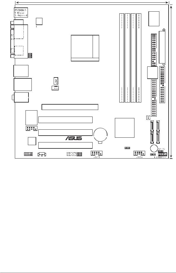
1 . 2 . 3 Motherboard layout
24.5cm (9.6in)
COM1
A
T
|
|
|
|
L |
|
939 |
|
|
|
|
|
|
|
|
Socket |
|
|
|
|
P |
|
USBPW12 USBPW34 |
|
|
|
|
|
|
|||
|
|
SPDIF_O |
|
|
|
||
|
|
|
|
|
|
|
|
|
|
|
|
|
|
|
|
F_USB12
USBLANCON SYS_FAN 
 CPU_FAN
T
Center:Line Out
Bottom:Mic In
VIA VT6307 |
PCIESLOT1 |
|
A8NE-FM |
|
|
|
|
|
|
PCI_SLOT1 |
|
IE1394_2 |
PCI_SLOT2 |
CR2032 3V |
|
|
Lithium Cell |
|
® |
CMOS Power |
ACL655 |
|
|
|
PCI_SLOT3 |
|
FAUDIO |
|
|
|
AUX |
|
* optional
|
|
|
|
ASUS |
|
|
|
|
|
|
A8000 |
|
|
bit,184-pin module) |
bit,184-pin module) |
bit,184-pin module) |
bit,184-pin module) |
FLOPPY1 |
|
|
|
|
|||||
|
A |
|
||||
(64 |
(64 |
(64 |
(64 |
|
|
|
DIMMA1 |
DIMMB1 |
DIMMA2 |
DIMMB2 |
4Mb |
|
|
|
|
|
|
BIOS |
|
|
DDR |
DDR |
DDR |
DDR |
IDE2 |
|
|
|
|
* |
* |
|
|
IDE1 |
|
|
|
|
|
||
|
|
|
CHIP_FAN |
SATA3 |
||
nVIDIA |
|
|
SATA4 |
|||
CK804 |
|
|
|
|
|
|
|
|
|
|
SATA1 |
SATA2 |
|
BIOS_R |
|
|
|
BUZZER1 |
|
|
|
|
|
|
CLPSW |
|
|
24.5cm (9.6in)
1 - 4 |
Chapter 1: Hardware information |

1.2.4Layout contents
S l o t s |
P a g e |
||
1. |
DDR DIMM slots |
1-12 |
|
|
|
|
|
2. |
PCI slots |
1-16 |
|
|
|
|
|
3. |
PCI Express slot |
1-16 |
|
Jumpers |
P a g e |
|
1. |
Clear RTC RAM (3-pin CLRTC1) |
1-17 |
2. |
Clear password (3-pin CLPSW) |
1-18 |
3. |
USB device wake-up (3-pin USBPW12, USBPW34, USBPW56, USBPW78) |
1-18 |
|
|
|
4. BIOS Recovery (3-pin BIOS_R) |
1-19 |
|
|
|
|
Rear panel connectors |
P a g e |
||
1. |
PS/2 mouse port |
1-20 |
|
2. |
Parallel port |
1-20 |
|
3. |
IEEE 1394a port |
1-20 |
|
4. |
LAN (RJ-45) port |
1-20 |
|
|
|
|
|
5. |
Line In port |
1-20 |
|
|
|
|
|
6. |
Line Out port |
1-20 |
|
|
|
|
|
7. |
Microphone port |
1-20 |
|
|
|
|
|
8. |
USB 2.0 ports 3 and 4 |
1-21 |
|
9. |
USB 2.0 ports 1 and 2 |
1-21 |
|
10. |
Coaxial S/PDIF Out port |
1-21 |
|
|
|
|
|
11. |
Serial port |
1-21 |
|
|
|
|
|
12. |
PS/2 keyboard port |
1-21 |
|
|
|
|
|
ASUS A8NE-FM |
1 - 5 |

Internal connectors |
P a g e |
|||
1. |
Floppy disk drive connector (34-1 pin FLOPPY1) |
1-22 |
||
2. |
IDE connectors (40-1 pin IDE1, IDE2) |
1-23 |
||
3. |
Serial ATA connectors (7-pin SATA1, SATA2, SATA3, SATA4) |
1-24 |
||
4. |
CPU fan connector (3-pin CPU_FAN) |
1-25 |
||
|
|
|
||
5. |
System fan connector (3-pin SYS_FAN) |
1-25 |
||
|
|
|
||
6. |
Chip fan connector (2-pin CHIP_FAN) |
1-25 |
||
|
|
|
||
7. |
USB connectors (10-1 pin USB78, USB56) |
1-26 |
||
|
|
|
||
8. |
IEEE 1394a connector (10-1 pin IE1394_2) |
1-26 |
||
9. ATX power connectors (24-pin ATXPWRCON1, 4-pin ATX12V1) |
1-27 |
|||
10. |
Internal audio connector (4-pin AUX) |
1-28 |
||
|
|
|
||
11. |
Front panel audio connector (10-1 pin FPAUDIO) |
1-28 |
||
|
|
|
||
12. |
System panel connector (10-1 pin F_PANEL1) |
1-29 |
||
|
|
|
|
|
1 - 6 |
Chapter 1: Hardware information |
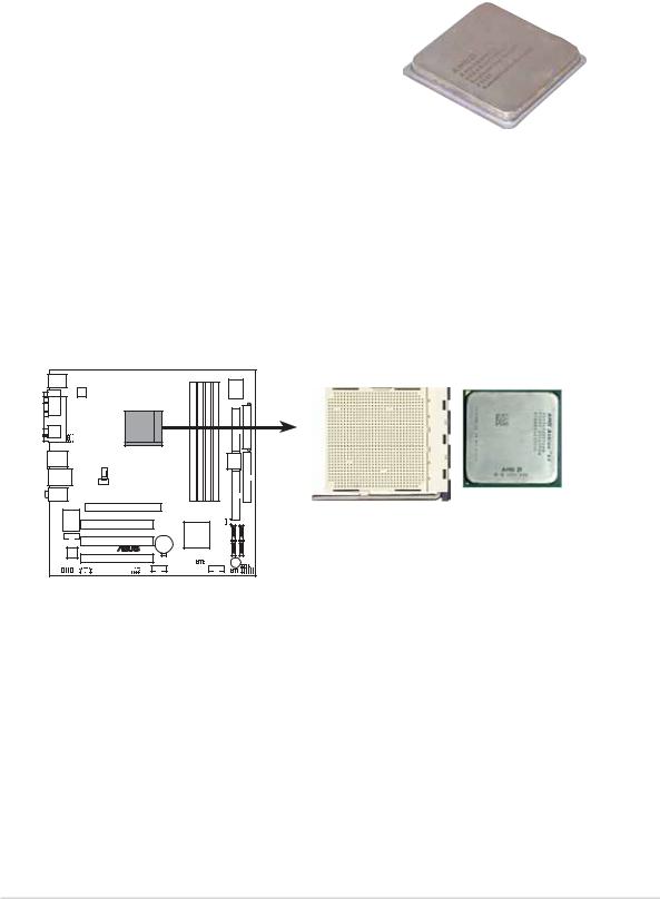
1.3Central Processing Unit (CPU)
The motherboard comes with a surface mount 939-pin Zero Insertion Force (ZIF) socket designed for the AMD Athlon™ 64FX or AMD Athlon 64™ processor.
The 128-bit-wide data paths of these processors can run applications faster than processors with only 32-bit or 64-bit wide data paths.
Take note of the marked corner (with gold triangle) on the CPU. This mark should match a specific corner on the socket to ensure correct installation.
Gold triangle 
1.3.1Installing the CPU
To install a CPU:
1.Locate the CPU socket on the motherboard.
A8NE-FM |
A8NE-FM CPU Socket 939
ASUS A8NE-FM |
1 - 7 |
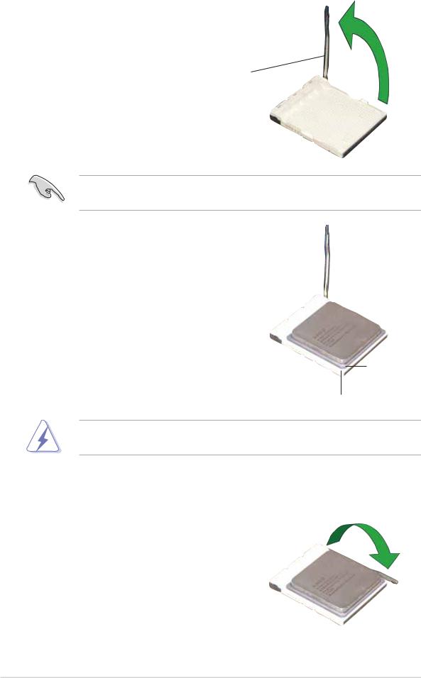
2.Unlock the socket by pressing the lever sideways, then lift it up to a 90°-100° angle.
Socket lever
Make sure that the socket lever is lifted up to 90°-100° angle; otherwise the CPU does not fit in completely.
3.Position the CPU above the socket such that the CPU corner with the gold triangle matches the socket corner with a small triangle.
4.Carefully insert the CPU into the socket until it fits in place.
G o l d triangle
Small triangle
The CPU fits only in one correct orientation. DO NOT force the CPU into the socket to prevent bending the pins and damaging the CPU!
5.When the CPU is in place, push down the socket lever to secure the CPU. The lever clicks on the side tab to indicate that it is locked.
1 - 8 |
Chapter 1: Hardware information |
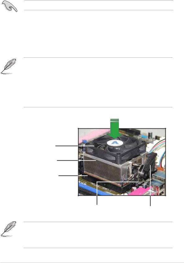
1.3.2Installing the heatsink and fan
The AMD Athlon™ 64FX or AMD Athlon 64™ processor requires a specially designed heatsink and fan assembly to ensure optimum thermal condition and performance.
Make sure that you use only qualified heatsink and fan assembly.
To install the CPU heatsink and fan:
1.Place the heatsink on top of the installed CPU, making sure that the heatsink fits properly on the retention module base.
• The retention module base is already installed on the motherboard upon purchase.
•You do not have to remove the retention module base when installing the CPU or installing other motherboard components.
•If you purchased a separate CPU heatsink and fan assembly, make sure that a Thermal Interface Material is properly applied to the CPU heatsink or CPU before you install the heatsink and fan assembly.
CP U fan
CPU heatsink
Retention module base
Retention bracket |
Retention bracket lock |
Your boxed CPU heatsink and fan assembly should come with installation instructions for the CPU, heatsink, and the retention mechanism. If the instructions in this section do not match the CPU documentation, follow the latter.
ASUS A8NE-FM |
1 - 9 |

2.Attach one end of the retention bracket to the retention module base.
3.Align the other end of the retention bracket (near the retention bracket lock) to the retention module base. A clicking sound denotes that the retention bracket is in place.
Make sure that the fan and heatsink assembly perfectly fits the retention mechanism module base, otherwise you cannot snap the retention bracket in place.
4.Push down the retention bracket lock on the retention mechanism to secure the heatsink and fan to the module base.
1 - 10 |
Chapter 1: Hardware information |
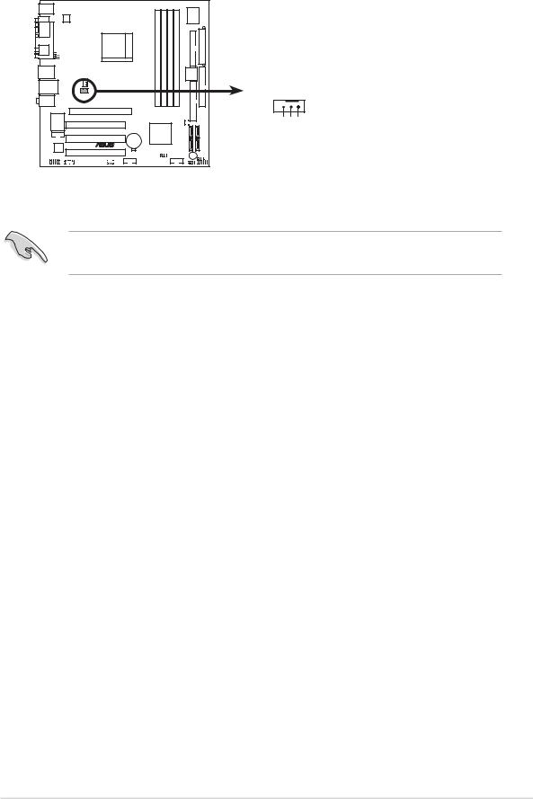
5.When the fan and heatsink assembly is in place, connect the CPU fan cable to the connector on the motherboard labeled CPU_FAN.
A8NE-FM |
CPU_FAN
GND
FANPWR
FAN_TACF1
A8NE-FM CPU fan connector
Do not forget to connect the CPU fan connector! Hardware monitoring errors can occur if you fail to plug this connector.
ASUS A8NE-FM |
1 - 11 |

1.4System memory
1.4.1Overview
The motherboard comes with four 184-pin Double Data Rate (DDR) Dual Inline Memory Modules (DIMM) sockets.
The following figure illustrates the location of the sockets:
A8NE-FM |
A8NE-FM 184-pin DDR DIMM sockets
DIMM A1 |
DIMM B1 |
DIMM A2 |
DIMM B2 |
Channel |
Sockets |
|
|
Channel A |
DIMM_A1 and DIMM_B1 |
|
|
Channel B |
DIMM_A2 and DIMM_B2 |
|
|
1.4.2Memory configurations
You may install 256 MB, 512 MB and 1 GB unbuffered non-ECC DDR DIMMs into the DIMM sockets using the memory configurations in this section.
•For dual-channel configuration, the total size of memory module(s) installed per channel must be the same for better performance (DIMM_A1+DIMM_B1=DIMM_A2+DIMM_B2).
•Always install DIMMs with the same CAS latency. For optimum compatibility, we recommend that you obtain memory modules from the same vendor. Refer to the DDR400 Qualified Vendors List on the next page for details.
•Due to chipset resource allocation, the system may detect less than 4 GB of system memory when you installed four 1 GB DDR memory modules.
•Due to chipset limitation, this motherboard does not support DIMM modules with 128 Mb memory chips or double-sided x16 memory chips.
•With the 4 DIMM slot, the DIMM slots DIMM_A2 and DIMM_B2 are always to be populated in pairs.
1 - 12 |
Chapter 1: Hardware information |
1.4.3Installing a DIMM
Make sure to unplug the power supply before adding or removing DIMMs or other system components. Failure to do so may cause severe damage to both the motherboard and the components.
1.Unlock a DIMM socket by pressing the retaining clips outward.
2.Align a DIMM on the socket such that the notch on the DIMM matches the break on the
socket. 1
2
DDR DIMM notch
1
Unlocked retaining clip
A DDR DIMM is keyed with a notch so that it fits in only one direction. DO NOT force a DIMM into a socket to avoid damaging the DIMM.
3.Firmly insert the DIMM into the socket until the retaining clips snap back in place and the DIMM is properly seated.
Locked retaining clip
1.4.4Removing a DIMM
To remove a DIMM:
1.Simultaneously press the retaining clips outward to unlock the DIMM.
2
1
1 |
DDR DIMM notch |
|
Support the DIMM lightly with your fingers when pressing the retaining clips. The DIMM might get damaged when it flips out with extra force.
2.Remove the DIMM from the socket.
ASUS A8NE-FM |
1 - 13 |

1.5Expansion slots
In the future, you may need to install expansion cards. The following sub-sections describe the slots and the expansion cards that they support.
Make sure to unplug the power cord before adding or removing expansion cards. Failure to do so may cause you physical injury and damage motherboard components.
1.5.1Installing an expansion card
To install an expansion card:
1.Before installing the expansion card, read the documentation that came with it and make the necessary hardware settings for the card.
2.Remove the system unit cover (if your motherboard is already installed in a chassis).
3.Remove the bracket opposite the slot that you intend to use. Keep the screw for later use.
4.Align the card connector with the slot and press firmly until the card is completely seated on the slot.
5.Secure the card to the chassis with the screw you removed earlier.
6.Replace the system cover.
1.5.2Configuring an expansion card
After installing the expansion card, configure it by adjusting the software settings.
1.Turn on the system and change the necessary BIOS settings, if any. See Chapter 2 for information on BIOS setup.
2.Assign an IRQ to the card. Refer to the tables on the next page.
3.Install the software drivers for the expansion card.
1 - 14 |
Chapter 1: Hardware information |

Standard interrupt assignments
I R Q |
Priority |
Standard Function |
0 |
1 |
System Timer |
|
|
|
1 |
2 |
Keyboard Controller |
|
|
|
2 |
- |
Re-direct to IRQ#9 |
|
|
|
3 |
11 |
Communications Port (COM2)* |
|
|
|
4 |
12 |
Communications Port (COM1)* |
|
|
|
5 |
13 |
IRQ holder for PCI steering* |
|
|
|
6 |
14 |
Floppy Disk Controller |
|
|
|
7 |
15 |
Printer Port (LPT1)* |
|
|
|
8 |
3 |
System CMOS/Real Time Clock |
|
|
|
9 |
4 |
IRQ holder for PCI steering* |
|
|
|
10 |
5 |
IRQ holder for PCI steering* |
11 |
6 |
IRQ holder for PCI steering* |
12 |
7 |
PS/2 Compatible Mouse Port* |
|
|
|
13 |
8 |
Numeric Data Processor |
|
|
|
14 |
9 |
Primary IDE Channel |
15 |
10 |
Secondary IDE Channel |
|
|
|
* These IRQs are usually available for ISA or PCI devices.
IRQ assignments for this motherboard
|
|
A |
B |
C |
D |
E |
F |
G |
H |
|
|
|
|
|
|
|
|
|
|
|
PCI slot 1 |
used |
— |
— |
— |
— |
— |
— |
— |
|
PCI slot 2 |
— |
used |
— |
— |
— |
— |
— |
— |
|
PCI slot 3 |
— |
— |
used |
— — — — — |
||||
|
Onboard IEEE 1394a controller |
— |
— |
— |
used |
— |
— |
— |
— |
When using PCI cards on shared slots, ensure that the drivers support “Share IRQ” or that the cards do not need IRQ assignments; otherwise, conflicts will arise between the two PCI groups, making the system unstable and the card inoperable.
ASUS A8NE-FM |
1 - 15 |
Loading...