


A7V600-F
Table of contents
 Loading...
Motherboard
A7V600-F
User Guide

ii
Checklist
Copyright © 2003 ASUSTeK COMPUTER INC. All Rights Reserved.
No part of this manual, including the products and software described in it, may be
reproduced, transmitted, transcribed, stored in a retrieval system, or translated into any
language in any form or by any means, except documentation kept by the purchaser for
backup purposes, without the express written permission of ASUSTeK COMPUTER INC.
(“ASUS”).
Product warranty or service will not be extended if: (1) the product is repaired, modified or
altered, unless such repair, modification of alteration is authorized in writing by ASUS; or (2)
the serial number of the product is defaced or missing.
ASUS PROVIDES THIS MANUAL “AS IS” WITHOUT WARRANTY OF ANY KIND, EITHER
EXPRESS OR IMPLIED, INCLUDING BUT NOT LIMITED TO THE IMPLIED WARRANTIES
OR CONDITIONS OF MERCHANTABILITY OR FITNESS FOR A PARTICULAR PURPOSE.
IN NO EVENT SHALL ASUS, ITS DIRECTORS, OFFICERS, EMPLOYEES OR AGENTS BE
LIABLE FOR ANY INDIRECT, SPECIAL, INCIDENTAL, OR CONSEQUENTIAL DAMAGES
(INCLUDING DAMAGES FOR LOSS OF PROFITS, LOSS OF BUSINESS, LOSS OF USE
OR DATA, INTERRUPTION OF BUSINESS AND THE LIKE), EVEN IF ASUS HAS BEEN
ADVISED OF THE POSSIBILITY OF SUCH DAMAGES ARISING FROM ANY DEFECT OR
ERROR IN THIS MANUAL OR PRODUCT.
SPECIFICATIONS AND INFORMATION CONTAINED IN THIS MANUAL ARE FURNISHED
FOR INFORMATIONAL USE ONLY, AND ARE SUBJECT TO CHANGE AT ANY TIME
WITHOUT NOTICE, AND SHOULD NOT BE CONSTRUED AS A COMMITMENT BY ASUS.
ASUS ASSUMES NO RESPONSIBILITY OR LIABILITY FOR ANY ERRORS OR
INACCURACIES THAT MAY APPEAR IN THIS MANUAL, INCLUDING THE PRODUCTS
AND SOFTWARE DESCRIBED IN IT.
Products and corporate names appearing in this manual may or may not be registered
trademarks or copyrights of their respective companies, and are used only for identification or
explanation and to the owners’ benefit, without intent to infringe.
E1341
First Edition
August 2003

iii
Features
Contents
Notices ............................................................................................ v
Safety information .......................................................................... vi
About this guide ............................................................................. vii
ASUS contact information .............................................................. ix
A7V600-F specifications summary .................................................. x
Chapter 1: Product introduction
1.1 Welcome! ........................................................................... 1-1
1.2 Special features .................................................................. 1-1
1.2.1 Product highlights .................................................. 1-1
1.2.2 Value-added solutions ............................................ 1-3
1.3 Motherboard overview ........................................................ 1-4
1.3.1 Major components ................................................. 1-4
1.3.2 Core specifications ................................................ 1-6
Chapter 2: Hardware information
2.1 Motherboard installation ..................................................... 2-1
2.1.1 Placement direction ............................................... 2-1
2.1.2 Screw holes ........................................................... 2-1
2.2 Motherboard layout ............................................................ 2-2
2.3 Before you proceed ............................................................ 2-3
2.4 Central Processing Unit (CPU) ........................................... 2-4
2.4.1 Overview ................................................................ 2-4
2.4.2 Installing the CPU .................................................. 2-5
2.5 System memory ................................................................. 2-6
2.5.1 Overview ................................................................ 2-6
2.5.2 DDR400 Qualified Vendor List ............................... 2-7
2.5.3 Installing a DIMM ................................................... 2-8
2.5.4 Removing a DIMM ................................................. 2-9
2.6 Expansion slots ................................................................ 2-10
2.6.1 Installing an expansion card ................................ 2-10
2.6.2 Configuring an expansion card ............................ 2-10
2.6.3 PCI slots .............................................................. 2-12
2.6.4 AGP slot ............................................................... 2-12
2.6.5 CNR slot .............................................................. 2-13
2.7 Jumpers ............................................................................ 2-14
2.8 Connectors ....................................................................... 2-17

iv
Safeguards
Contents
Chapter 3: Powering up
3.1 Starting up for the first time ................................................ 3-1
3.2 Powering off the computer ................................................. 3-2
Chapter 4: BIOS setup
4.1 Managing and updating your BIOS .................................... 4-1
4.1.1 Using ASUS EZ Flash to update the BIOS ............ 4-1
4.1.2 Using AFLASH to update the BIOS ....................... 4-3
4.1.3 Recovering the BIOS with CrashFree BIOS 2 ....... 4-7
4.2 BIOS Setup program .......................................................... 4-9
4.2.1 BIOS menu bar .................................................... 4-10
4.2.2 Legend bar ........................................................... 4-10
4.3 Main Menu ........................................................................ 4-12
4.3.1 Primary and Secondary Master/Slave ................. 4-14
4.3.2 Keyboard Features .............................................. 4-18
4.4 Advanced Menu ............................................................... 4-19
4.4.1 Chip Configuration ............................................... 4-22
4.4.2 I/O Device Configuration ...................................... 4-25
4.4.3 PCI Configuration ................................................ 4-28
4.5 Power Menu ..................................................................... 4-30
4.5.1 Power Up Control ................................................ 4-32
4.5.2 Hardware Monitor ................................................ 4-34
4.6 Boot Menu ........................................................................ 4-35
4.7 Exit Menu ......................................................................... 4-37
v
Notices
Federal Communications Commission Statement
This device complies with FCC Rules Part 15. Operation is subject to the
following two conditions:
• This device may not cause harmful interference, and
• This device must accept any interference received including interference
that may cause undesired operation.
This equipment has been tested and found to comply with the limits for a
Class B digital device, pursuant to Part 15 of the FCC Rules. These limits
are designed to provide reasonable protection against harmful interference
in a residential installation. This equipment generates, uses and can radiate
radio frequency energy and, if not installed and used in accordance with
manufacturer’s instructions, may cause harmful interference to radio
communications. However, there is no guarantee that interference will not
occur in a particular installation. If this equipment does cause harmful
interference to radio or television reception, which can be determined by
turning the equipment off and on, the user is encouraged to try to correct the
interference by one or more of the following measures:
• Reorient or relocate the receiving antenna.
• Increase the separation between the equipment and receiver.
• Connect the equipment to an outlet on a circuit different from that to
which the receiver is connected.
• Consult the dealer or an experienced radio/TV technician for help.
Canadian Department of Communications Statement
This digital apparatus does not exceed the Class B limits for radio noise
emissions from digital apparatus set out in the Radio Interference
Regulations of the Canadian Department of Communications.
This class B digital apparatus complies with Canadian ICES-003.
The use of shielded cables for connection of the monitor to the
graphics card is required to assure compliance with FCC regulations.
Changes or modifications to this unit not expressly approved by the
party responsible for compliance could void the user’s authority to
operate this equipment.

vi
Safety information
Electrical safety
• To prevent electrical shock hazard, disconnect the power cable from
the electrical outlet before relocating the system.
• When adding or removing devices to or from the system, ensure that
the power cables for the devices are unplugged before the signal
cables are connected. If possible, disconnect all power cables from the
existing system before you add a device.
• Before connecting or removing signal cables from the motherboard,
ensure that all power cables are unplugged.
• Seek professional assistance before using an adpater or extension
cord. These devices could interrupt the grounding circuit.
• Make sure that your power supply is set to the correct voltage in your
area. If you are not sure about the voltage of the electrical outlet you
are using, contact your local power company.
• If the power supply is broken, do not try to fix it by yourself. Contact a
qualified service technician or your retailer.
Operation safety
• Before installing the motherboard and adding devices on it, carefully
read all the manuals that came with the package.
• Before using the product, make sure all cables are correctly connected
and the power cables are not damaged. If you detect any damage,
contact your dealer immediately.
• To avoid short circuits, keep paper clips, screws, and staples away from
connectors, slots, sockets and circuitry.
• Avoid dust, humidity, and temperature extremes. Do not place the
product in any area where it may become wet.
• Place the product on a stable surface.
• If you encounter technical problems with the product, contact a
qualified service technician or your retailer.

vii
About this guide
This user guide contains the information you need when installing the
ASUS A7V600-F motherboard.
How this guide is organized
This manual contains the following parts:
• Chapter 1: Product introduction
This chapter describes the features of the A7V600-F motherboard. It
includes brief descriptions of the special attributes of the motherboard
and the new technology it supports.
• Chapter 2: Hardware information
This chapter lists the hardware setup procedures that you have to
perform when installing system components. It includes description of
the switches, jumpers, and connectors on the motherboard.
• Chapter 3: Powering up
This chapter describes the power up sequence and gives information
on the BIOS beep codes.
• Chapter 4: BIOS setup
This chapter tells how to change system settings through the BIOS
Setup menus. Detailed descriptions of the BIOS parameters are also
provided.
viii
Conventions used in this guide
To make sure that you perform certain tasks properly, take note of the
following symbols used throughout this manual.
Where to find more information
Refer to the following sources for additional information and for product
and software updates.
1. ASUS Websites
The ASUS websites worldwide provide updated information on ASUS
hardware and software products. The ASUS websites are listed in the
ASUS Contact Information on page ix.
2. Optional Documentation
Your product package may include optional documentation, such as
warranty flyers, that may have been added by your dealer. These
documents are not part of the standard package.
DANGER/WARNING: Information to prevent injury to yourself
when trying to complete a task.
CAUTION: Information to prevent damage to the components
when trying to complete a task.
IMPORTANT: Information that you MUST follow to complete a
task.
NOTE: Tips and additional information to aid in completing a task.

ix
ASUS contact information
ASUSTeK COMPUTER INC. (Asia-Pacific)
Address: 150 Li-Te Road, Peitou, Taipei, Taiwan 112
General Tel: +886-2-2894-3447
General Fax: +886-2-2894-3449
Web Site: www.asus.com.tw
Technical Support
MB/Others (Tel): +886-2-2890-7121 (English)
Notebook (Tel): +886-2-2890-7122 (English)
Desktop/Server (Tel): +886-2-2890-7123 (English)
Support Fax: +886-2-2890-7698
ASUS COMPUTER INTERNATIONAL (America)
Address: 44370 Nobel Drive, Fremont, CA 94538, USA
General Fax: +1-502-933-8713
General Email: tmd1@asus.com
Web Site: usa.asus.com
Technical Support
Support Fax: +1-502-933-8713
General Support: +1-502-995-0883
Notebook Support: +1-510-739-3777 x5110
Support Email: tsd@asus.com
ASUS COMPUTER GmbH (Germany and Austria)
Address: Harkortstr. 25, 40880 Ratingen, BRD, Germany
General Email: sales@asuscom.de (for marketing requests only)
General Fax: +49-2102-9599-31
Web Site: www.asuscom.de
Technical Support
Components: +49-2102-9599-0
Notebook PC: +49-2102-9599-10
Support Fax: +49-2102-9599-11
Support Email: www.asuscom.de/support (for online support)
ASUSTeK COMPUTER (Middle East and North Africa)
Address: P.O. Box 64133, Dubai, U.A.E.
General Tel: +9714-283-1774
General Fax: +9714-283-1775
Web Site: www.ASUSarabia.com
x
A7V600-F specifications summary
CPU
Chipset
Front Side Bus (FSB)
Memory
Expansion slots
Storage
Audio
LAN
Special Features
Back Panel I/O
Internal I/O
Connectors
(continued on the next page)
Socket A for AMD Athlon XP/Athlon with Thoroughbred/
Barton Core support
Northbridge: VIA KT600
Southbridge: VIA VT8237
400/333/266 Mhz
3 x 184-pin DDR DIMM Sockets support a maximum of 3GB
unbuffered non-ECC PC2700/2100 DDR SDRAM memory.
(Note: PC3200 maximum to 2 DIMMs only.)
Visit the ASUS website for the latest qualified DDR400 module list
1 x AGP 8X
5 x PCI
1 x ASUS proprietary CNR connector
2 x UltraATA133/100/66/33
2 x Serial ATA connectors
Realtek ALC655 6-channel CODEC
S/PDIF in/out interface
Realtek
®
8201BL LAN PHY
ASUS MyLogo
ASUS EZ Flash
Power Loss Restart
ASUS C.O.P. (CPU Overheating Protection)
ASUS Instant Music Lite
1 x Parallel
1 x Serial
1 x PS/2 Keyboard
1 x PS/2 Mouse
1 x Audio I/O
4 x USB 2.0
1 x RJ-45 Port
1 x S/PDIF out port
1 x 1394 port
CPU/power/chassis fan connectors
2 x Serial ATA connectors
20 pin ATX power connector
CD/AUX audio connectors
Front panel audio connector
2 x USB 2.0 connector supports additional 4 USB 2.0 ports
S/PDIF-In connector
xi
BIOS features
Industry standard
Manageability
Form Factor
Support CD contents
A7V600-F specifications summary
* Specifications are subject to change without notice.
2Mb Flash ROM, ASUS Jumperfree, Award BIOS, TCAV,
PnP, DMI2.0, WfM2.0, SM BIOS2.3, ASUS EZ Flash, ASUS
MyLogo
PCI 2.2, USB 2.0
WfM 2.0. DMI 2.0, WOR, WOL
ATX form factor: 12 in x 9.6 in (30.5 cm x 24.5 cm)
Device drivers
ASUS PC Probe
Trend Micro™ PC-cillin 2002 anti-virus software
(OEM version)
ASUS LiveUpdate Utility
xii

Chapter 1
This chapter describes the features of the
ASUS A7V600-F motherboard. It includes
brief explanations of the special attributes of
the motherboard and the new technology it
supports.
Product introduction

ASUS A7V600-F motherboard
Chapter summary
1.1 Welcome! ........................................................ 1-1
1.2 Special features ............................................. 1-1
1.3 Motherboard overview ................................... 1-4

ASUS A7V600-F motherboard user guide
1-1
1.2 Special features
1.2.1 Product highlights
400 FSB K7 Platform
The ASUS A7V600-F motherboard is loaded with the most advanced
technologies to deliver the maximum performance for socket A processors.
Based on the advanced VIA KT600 chipset with FSB 400 and DDR 400
support, the ASUS A7V600-F features AGP8X, USB 2.0 as well as a 6-
channel audio CODEC. Unique ASUS features such as ASUS C.O.P.,
ASUS MyLogo and more are included to ensure the best user experience
and value in a motherboard.
400MHz FSB Athlon XP CPU support
AMD’s Athlon XP 3200+ and all follow-up CPUs now support 400MHz
Front Side Bus (FSB) for increased office productivity and enhanced digital
media experience.
Serial ATA technology
The motherboard supports the new Serial ATA technology through the
SATA interfaces. The SATA specification allows for thinner, more flexible
cables with lower pin count, reduced voltage requirement, and up to
150MB/s data transfer rate.
1.1 Welcome!
Thank you for buying the ASUS
®
A7V600-F motherboard!
The ASUS A7V600-F motherboard is loaded with the most advanced
technologies to deliver the maximum performance for socket A processors.
Based on the advanced VIA KT600 chipset with FSB 400 and DDR 400
support, the ASUS A7V600-F also features Serial ATA support, AGP 8X,
USB 2.0 as well as 6-channel audio, 10/100 LAN PHY and S/PDIF
interfaces. Trademark ASUS features such as ASUS C.O.P., ASUS Instant
Music Lite and more are included to ensure the best user experience and
value in a motherboard.
Before you start installing the motherboard, and hardware devices on it,
check the items in your package with the list below.
1-2
Chapter 1: Product introduction
DDR400 (PC3200) support
DDR400 (PC3200), the latest and fastest DDR memory standard, supports
bandwidth up to 3.2 GB/s to provide enhanced system performance.
(Note: PC3200 maximum to 2 DIMMs only. Visit the ASUS website for the
latest qualified DDR400 module list.)
AGP 8X support
AGP 8X (AGP 3.0) is the next generation VGA interface specification that
enables enhanced graphics performance with high bandwidth speeds up
8 x USB 2.0 ports support
USB 2.0 is the latest connectivity standard for next generation components
and peripherals. USB 2.0 delivers fast transfer speeds up to 40 times
faster at 480 MB/s, for easy connectivity and ultra-fast data transfers. The
higher bandwidth of USB 2.0 allows connection of devices such as high
resolution video conferencing cameras, next generation scanners, printers,
and fast storage units. USB 2.0 is backward compatible with USB 1.1.
Digital audio support
The A7V600-F provides convenient connectivity to external home theater
audio systems via an S/PDIF out interface in the rear panel and an
onboard S/PDIF In connector. Experience 5.1-channel surround sound
and enhanced 3D audio while playing your favorite DVDs or games.
C.O.P. (CPU Overheating Protection)
With AMD
®
Athlon XP™ installed, the motherboard offers automatic CPU
Overheating Protection to prolong the life of the entire system. If the CPU
temperature exceeds the set criteria, the PC shuts down automatically.
ASUS MyLogo™
This new feature present in the A7V600-F motherboard allows you to
personalize and add style to your system with customizable boot logos.
ASUS EZ Flash BIOS
With the ASUS EZ Flash, you can easily update the system BIOS even
before loading the operating system. No need to use a DOS-based utility
or boot from a floppy disk.

ASUS A7V600-F motherboard user guide
1-3
1.2.2 Value-added solutions
Temperature, fan, and voltage monitoring
The CPU temperature is monitored by the ASUS ASIC to prevent
overheating and damage. The system fan rotations per minute (RPM) is
monitored for timely failure detection. The system voltage levels are
monitored to ensure stable supply of current for critical components.
ASUS update
This utility allows you to update the motherboard BIOS through a user-
friendly interface. Connect to the Internet then to the ASUS FTP site
nearest you to obtain the latest BIOS version for your motherboard.

1-4
Chapter 1: Product introduction
1.3 Motherboard overview
Before you install the A7V600-F motherboard, familiarize yourself with its
physical configuration and available features to facilitate the motherboard
installation and future upgrades. A sufficient knowledge of the motherboard
specifications will also help you avoid mistakes that may damage the
board and its components.
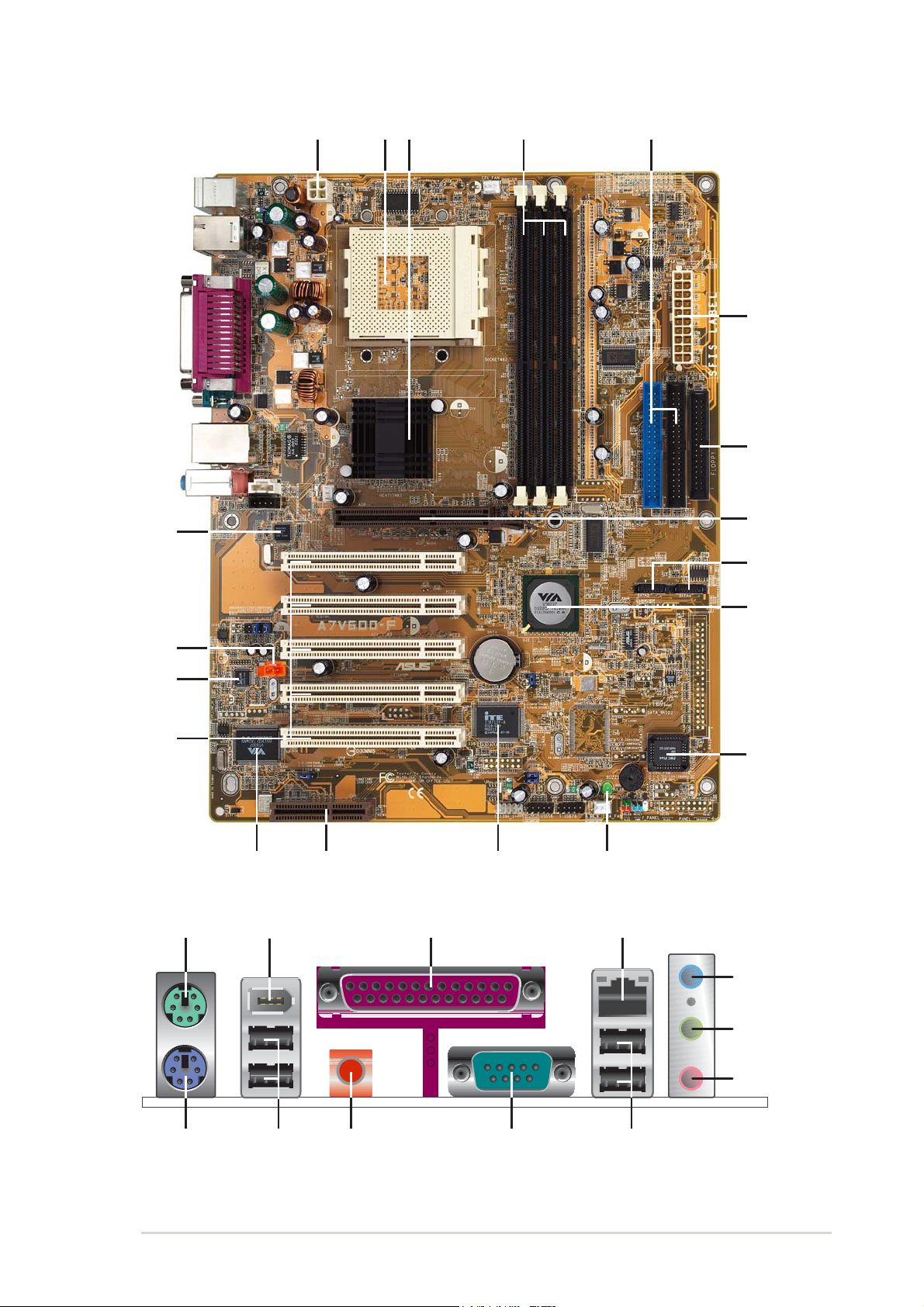
1.3.1 Major components
The following are the major components of the A7V600-F motherboard as
pointed out in the picture on page 1-7.
1. 4-pin ATX power connector
2. CPU socket
3. North Bridge controller
4. DDR DIMM sockets
5. IDE connectors
6. ATX power connector
7. Floppy disk connector
8. AGP slot
9. Serial ATA connectors
10. South Bridge controller
11. Flash ROM
12. Stand-by LED
13. Super I/O controller
14. CNR slot
15. IEEE 1394 controller
16. PCI slots
See page 1-7 for the specifications of each major component. Refer to
Chapter 2 for detailed information on the components.
17. Audio CODEC
18. S/PDIF in
19. LAN controller
20. Mouse port
21. IEEE 1394 port
22. Parallel port
23. RJ-45 port
24. Line In jack
25. Line Out jack
26. Microphone jack
27. USB 2.0 ports 1 and 2
28. Serial port (COM1)
29. S/PDIF out port
30. USB 2.0 ports 3 and 4
31. Keyboard port
ASUS A7V600-F motherboard user guide
1-5
43
8
2
1
0
16
12
6
5
7
1
1
13
17
19
1
14
9
15
18
20
31
2
4
2
5
2
6
27
22 23
2829
21
30
1-6
Chapter 1: Product introduction
ATX 12V connector. This power connector connects the 4-pin 12V
plug from the ATX 12V power supply.
CPU socket. Socket 462 (Socket A) surface mount, Zero Insertion
Force (ZIF) socket for the AMD Athlon XP/Athlon Processors.
North bridge controller. The VIA
®
KT600 supports AGP 8X mode,
400/333/266MHz Front Side Bus, and the latest 400/333/266MHz
64-bit memory bus.
DDR DIMM sockets. These three 184-pin DIMM sockets support
up to 3GB system memory using unbuffered non-ECC PC2700/
2100 DDR DIMMs.
(Note: PC3200 maximum to 2 DIMMs support only.
Visit the ASUS website (www.asus.com) for the latest qualified DDR400
module list.)
IDE connectors. These dual-channel bus master IDE connectors
support up to four Ultra DMA133/100/66, PIO Modes 3 & 4 IDE
devices. Both the primary (blue) and secondary (black) connectors
are slotted to prevent incorrect insertion of the IDE ribbon cable.
ATX power connector. This 20-pin connector connects to an ATX
+12V power supply. The power supply must have at least 1A on the
+5V standby lead (+5VSB).
Floppy disk connector. This connector accommodates the
provided ribbon cable for the floppy disk drive. One side of the
connector is slotted to prevent incorrect insertion of the floppy disk
cable.
AGP slot. This Accelerated Graphics Port (AGP) slot supports 1.5V
AGP8X mode graphics cards for 3D graphical applications.
SATA connectors. These connectors support Serial ATA HDDs
and allows up to 150MB/s data transfer rate, faster than the
standard Parallel ATA with 133MB/s.
South bridge controller. The VIA
®
VT8237 integrated peripheral
controller supports various I/O functions including 2-channel ATA/
133 bus master IDE controller, up to eight USB 2.0 ports, LPC
Super I/O interface, AC’97 interface and PCI 2.2 interface.
Flash ROM. This 2Mb firmware contains the programmable BIOS
program.
10
9
8
7
6
5
4
3
2
1
1.3.2 Core specifications
11
ASUS A7V600-F motherboard user guide
1-7
24
23
Standby power LED. This LED lights up if there is a standby
power on the motherboard. This LED acts as a reminder to turn off
the system power before plugging or unplugging devices.
Super I/O controller. This Low Pin Count (LPC) interface provides
the commonly used Super I/O functionality. The chipset supports a
high-performance floppy disk controller for a 360K/720K/1.44M/
2.88M floppy disk drive, a multi-mode parallel port, two standard
compatible UARTs, and a Flash ROM interface.
CNR slot. This slot is specifically designed for the Communications
and Networking Riser (CNR) card. The CNR supports V.90 analog
modem.
IEEE 1394 controller. The VIA
®
VT6307 controller chipset supports
two low power IEEE 1394 connectors to allow 100Mbps, 200Mbps,
and 400Mbps data transfers between the 1394 devices.
PCI slots. These five 32-bit PCI 2.2 expansion slots support bus
master PCI cards like SCSI or LAN cards with 133MB/s maximum
throughput.
Audio CODEC . The ALC 655 is an AC’97 compliant audio CODEC
for PC multimedia systems.
S/PDIF In connector. This connector is for an additional S/PDIF
audio module that allows digital instead of analog sound input.
LAN PHY. The Realtek
®
8201BL LAN PHY with the 10/100 MAC
built in the VT8237 chipset provides your local area networking
needs. Ideal for handling large amounts of data such as video,
audio and voice.
PS/2 mouse port. This green 6-pin connector is for a PS/2 mouse.
IEEE 1394 port. This port connects IEEE 1394-compliant devices
like camcorders, VCRs, printers, or digital cameras.
Parallel port. This 25-pin port connects a parallel printer, a
scanner, or other devices.
RJ-45 port. This port allows connection to a Local Area Network
(LAN) through a network hub.
Line In jack. This Line In (light blue) jack connects a tape player or
other audio sources. In 6-channel mode, the function of this jack
becomes Rear Speaker Out.
12
13
14
15
16
17
18
22
21
20
19
1-8
Chapter 1: Product introduction
USB 2.0 ports 3 and 4. These two 4-pin Universal Serial Bus
(USB) ports are available for connecting USB 2.0 devices.
Serial port (COM1). This 9-pin serial port is for an additional serial
device.
S/PDIF out jack. This jack connects to external audio output
devices.
USB 2.0 ports 1 and 2. These two 4-pin Universal Serial Bus
(USB) ports are available for connecting USB 2.0 devices.
PS/2 keyboard port. This purple 6-pin connector is for a PS/2
keyboard.
27
28
29
30
Line Out jack. This Line Out (lime) jack connects a headphone or
a speaker. In 6-channel mode, the function of this jack becomes
Front Speaker Out.
Microphone jack. This Mic (pink) jack connects a microphone. In
6-channel mode, the function of this jack becomes Center Speaker/
Subwoofer.
Headphone/
Connector 2-Speaker 4-Speaker 6-Speaker
Light Blue Line In Line In Rear Speaker Out
Lime Line Out Front Speaker Out Front Speaker Out
Pink Mic In Rear Speaker Out Center Spkr/Subwoofer
25
31
26
Chapter 2
Hardware information
This chapter describes the hardware setup
procedures that you have to perform when
installing system components. It includes
details on the switches, jumpers, and
connectors on the motherboard.

ASUS A7V600-F motherboard
Chapter summary
2.1 Motherboard installation ............................... 2-1
2.2 Motherboard layout ....................................... 2-2
2.3 Before you proceed ....................................... 2-3
2.4 Central Processing Unit (CPU) ..................... 2-4
2.5 System memory ............................................. 2-6
2.6 Expansion slots ........................................... 2-10
2.7 Jumpers ........................................................ 2-14
2.8 Connectors ................................................... 2-17
ASUS A7V600-F motherboard user guide
2-1
2.1 Motherboard installation
Before you install the motherboard, study the configuration of your chassis
to ensure that the motherboard fits into it. The A7V600-F uses the ATX
form factor that measures 12 inches x 9.6 inches (30.5 x 24.5 cm).
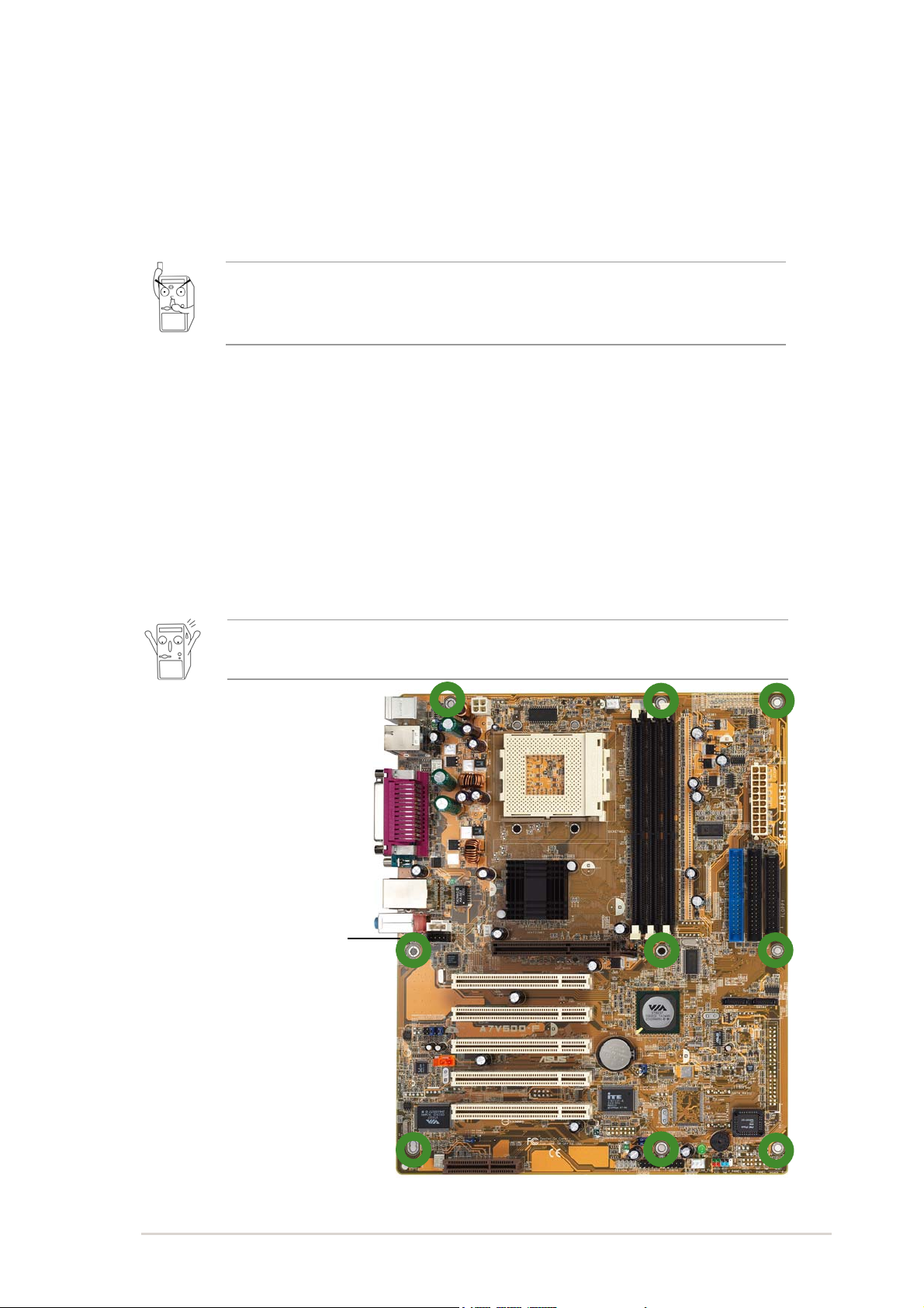
2.1.1 Placement direction
When installing the motherboard, make sure that you place it into the
chassis in the correct orientation. The edge with external ports goes to the
rear part of the chassis as indicated in the image below.
2.1.2 Screw holes
Place nine (9) screws into the holes indicated by circles to secure the
motherboard to the chassis.
Place this side towards
the rear of the chassis
Do not overtighten the screws! Doing so may damage the
motherboard.
Make sure to unplug the power cord before installing or removing the
motherboard. Failure to do so may cause you physical injury and
damage motherboard components.
2-2
Chapter 2: Hardware information
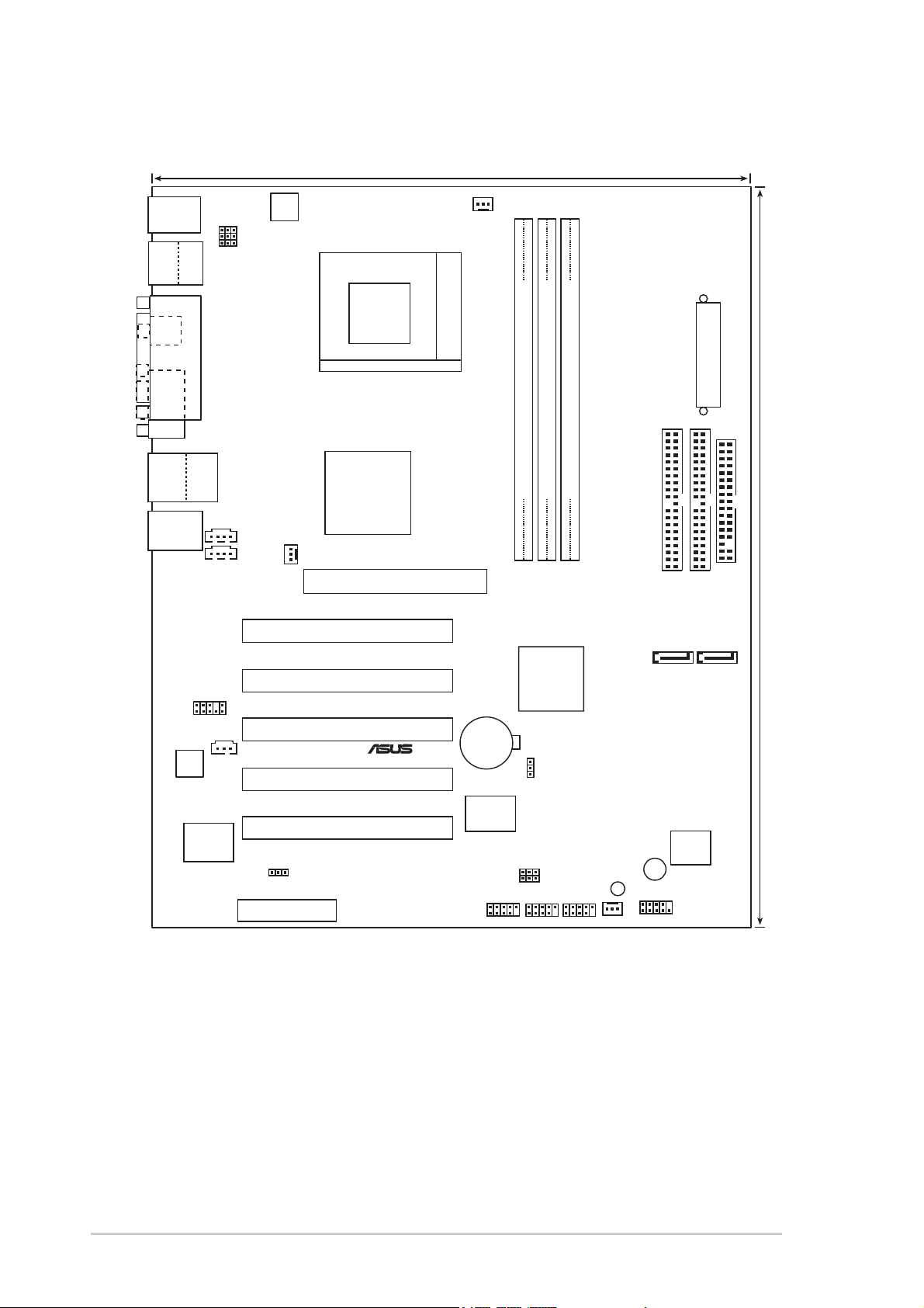
2.2 Motherboard layout
24.5cm (9.6in)
30.5cm (12.0in)
PCI1
A7V600-F
®
CD
AUX
Super
I/O
2Mbit
Low Pin
Count
Accelerated Graphics Port (AGP)
CPU_FAN
FP_AUDIO
ALC655
USB2.0
T: USB4
B: USB3
Top:
RJ-45
FLOPPY
PRI_IDE
SEC_IDE
ATX Power Connector
DDR DIMM1 (64/72 bit,184-pin module)
PWR_FAN
KBPWR
CHA_FAN
SB_PWR
VIA
VT8237
South
Bridge
USB56
CR2032 3V
Lithium Cell
CMOS Power
USBPW34
CLRTC
USBPW56
PARALLEL PORT
SPDIF_O
COM1
PCI2
PCI3
PCI4
PCI5
DDR DIMM2 (64/72 bit,184-pin module)
DDR DIMM3 (64/72 bit,184-pin module)
USBPW12
VIA
KT600
Chipset
USBPW78
USB78
BUZZ1
PS/2KBMS
T: Mouse
B: Keyboard
Below:Mic In
Center:Line Out
Top:Line In
Socket 462
F_PANEL
ATX12V
1394
Top:
USB1
USB2
Bottom:
SPDIF _IN
CNR1
1394_SW
IE1394_1
VIA
VT6307
Chipset
SATA1SATA2
ASUS A7V600-F motherboard user guide
2-3
2.3 Before you proceed
Take note of the following precautions before you install motherboard
components or change any motherboard settings.
1. Unplug the power cord from the wall socket before touching any
component.
2. Use a grounded wrist strap or touch a safely grounded object or to
a metal object, such as the power supply case, before handling
components to avoid damaging them due to static electricity.
3. Hold components by the edges to avoid touching the ICs on them.
4. Whenever you uninstall any component, place it on a grounded
antistatic pad or in the bag that came with the component.
5. Before you install or remove any component, ensure that the
ATX power supply is switched off or the power cord is
detached from the power supply. Failure to do so may cause
severe damage to the motherboard, peripherals, and/or
components.
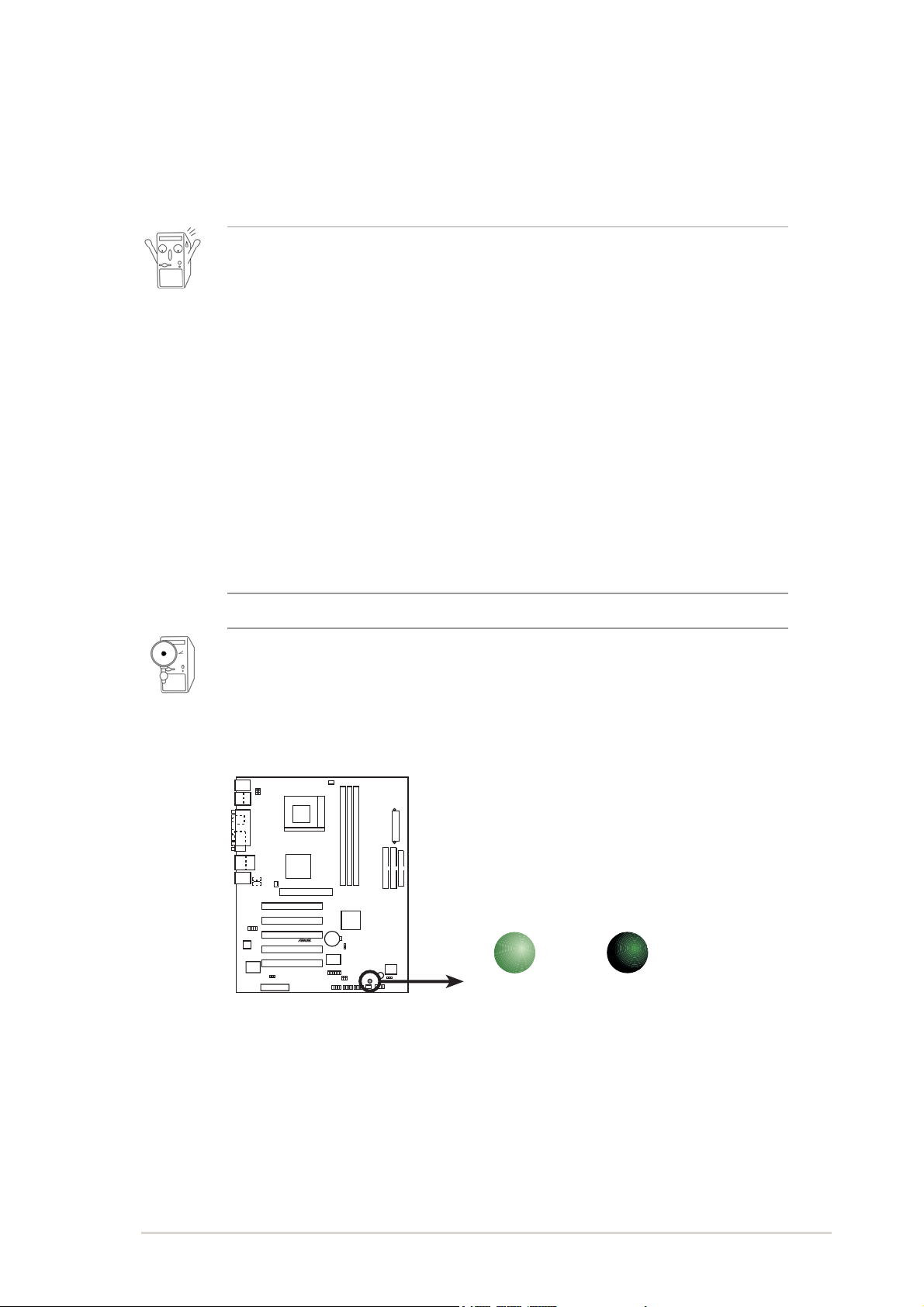
When lit, the green LED (SB_PWR1) indicates that the system is ON,
in sleep mode, or in soft-off mode, a reminder that you should shut
down the system before removing or plugging in any motherboard
component.
A7V600-F
®
A7V600-F Onboard LED
SB_PWR
ON
Standby
Power
OFF
Powere
d
Off
2-4
Chapter 2: Hardware information
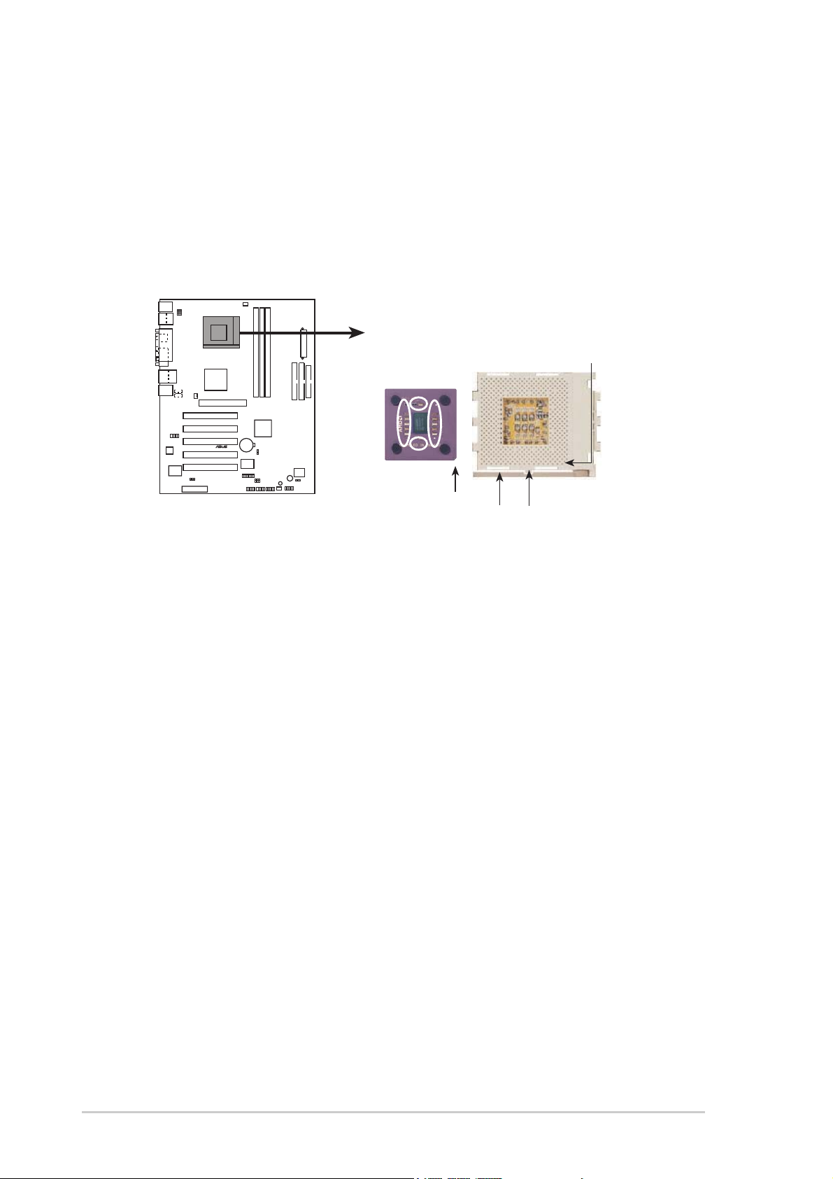
2.4 Central Processing Unit (CPU)
2.4.1 Overview
The motherboard provides a Socket A (462) for CPU installation. AMD
processors offer gigahertz speeds to support all the latest computing platforms
and applications. The A7V600-F supports Athlon
TM
XP and Athlon
TM
processors with Thoroughbred/Barton core support.
Each AMD CPU has a “marked” corner. This corner is indicated with a notch,
and/or a golden square or triangle. Refer to this indicator while orienting the
CPU. See the next section for installation details.
A fan and heatsink should be attached to the CPU to prevent overheating.
A7V600-F
®
A7V600-F Socket A
AMD™ CPU
CPU NOTCH
LOCK
CPU NOTCH
TO INNER
CORNER
LEVER
Loading...