


ASMB6-iKVM
Server Management Board

E6918
First Edition V1
January 2012
Copyright © 2012 ASUSTeK COMPUTER INC. All Rights Reserved.
No part of this manual, including the products and software described in it, may be reproduced, transmitted, transcribed, stored in a retrieval system, or translated into any language in any form or by any means, except documentation kept by the purchaser for backup purposes, without the express written permission of ASUSTeK COMPUTER INC. (“ASUS”).
Product warranty or service will not be extended if: (1) the product is repaired, modified or altered, unless such repair, modification of alteration is authorized in writing by ASUS; or (2) the serial number of the product is defaced or missing.
ASUS PROVIDES THIS MANUAL “AS IS” WITHOUT WARRANTY OF ANY KIND, EITHER EXPRESS OR IMPLIED, INCLUDING BUT NOT LIMITED TO THE IMPLIED WARRANTIES OR CONDITIONS OF MERCHANTABILITY OR FITNESS FOR A PARTICULAR PURPOSE. IN NO EVENT SHALL ASUS, ITS DIRECTORS, OFFICERS, EMPLOYEES OR AGENTS BE LIABLE FOR ANY INDIRECT, SPECIAL, INCIDENTAL, OR CONSEQUENTIAL DAMAGES (INCLUDING DAMAGES FOR LOSS OF PROFITS, LOSS OF BUSINESS, LOSS OF USE OR DATA, INTERRUPTION OF BUSINESS AND THE LIKE), EVEN IF ASUS HAS BEEN ADVISED OF THE POSSIBILITY OF SUCH DAMAGES ARISING FROM ANY DEFECT OR ERROR IN THIS MANUAL OR PRODUCT.
SPECIFICATIONS AND INFORMATION CONTAINED IN THIS MANUAL ARE FURNISHED FOR INFORMATIONAL USE ONLY, AND ARE SUBJECT TO CHANGE AT ANY TIME WITHOUT NOTICE, AND SHOULD NOT BE CONSTRUED AS A COMMITMENT BY ASUS. ASUS ASSUMES NO RESPONSIBILITY OR LIABILITY FOR ANY ERRORS OR INACCURACIES THAT MAY APPEAR IN THIS MANUAL, INCLUDING THE PRODUCTS AND SOFTWARE DESCRIBED IN IT.
Products and corporate names appearing in this manual may or may not be registered trademarks or copyrights of their respective companies, and are used only for identification or explanation and to the owners’ benefit, without intent to infringe.
ii

Contents
Contents....................................................................................................... |
iii |
Notices......................................................................................................... |
vi |
Safety information..................................................................................... |
viii |
About this guide.......................................................................................... |
ix |
ASMB6-iKVM specifications summary...................................................... |
xi |
Chapter 1: |
Product introduction |
|
|
1.1 |
Welcome! |
....................................................................................... |
1-2 |
1.2 |
Package contents......................................................................... |
1-2 |
|
1.3 |
Features......................................................................................... |
|
1-3 |
1.4 |
System requirements................................................................... |
1-4 |
|
1.5 |
Network setup............................................................................... |
1-5 |
|
Chapter 2: |
Installation |
|
|
2.1 |
Before you proceed...................................................................... |
2-2 |
|
2.2 |
Hardware installation................................................................... |
2-2 |
|
2.3 |
Firmware update and IP configuration....................................... |
2-4 |
|
|
2.3.1 |
Firmware update.............................................................. |
2-4 |
|
2.3.2 |
Configure BMC IP source static IP.................................. |
2-6 |
|
2.3.3 |
Configure BMC IP source DHCP..................................... |
2-7 |
2.4 |
BIOS configuration....................................................................... |
2-8 |
|
|
2.4.1 |
Running the BIOS BMC configuration............................. |
2-8 |
|
2.4.2 |
BMC network configuration............................................. |
2-8 |
|
2.4.3 |
System Event Log......................................................... |
2-10 |
2.5 |
Running the ASMC6 utility......................................................... |
2-11 |
|
|
2.5.1 |
Configuring the LAN controller...................................... |
2-13 |
|
2.5.2 |
Configuring the user name and password..................... |
2-14 |
2.6 |
Software installation................................................................... |
2-15 |
|
|
2.6.1 |
Installing the ARC.......................................................... |
2-15 |
|
2.6.2 |
Launching ARC.............................................................. |
2-16 |
Chapter 3: |
ASUS Remote Console |
|
|
3.1 |
ASUS Remote Console (ARC)..................................................... |
3-2 |
|
|
3.1.1 |
ARC sections................................................................... |
3-3 |
|
3.1.2 Connecting to the remote server..................................... |
3-6 |
|
|
3.1.3 |
Retrieving sensor information.......................................... |
3-8 |
iii

Contents
|
3.1.4 |
Displaying FRU information........................................... |
3-10 |
|
3.1.5 |
Displaying system event logs......................................... |
3-11 |
|
3.1.6 |
Using Remote Console.................................................. |
3-12 |
|
3.1.7 |
Displaying all remote server sensors............................. |
3-13 |
|
3.1.8 |
Adjusting the monitoring settings................................... |
3-14 |
|
3.1.9 |
Controlling the remote server power............................. |
3-16 |
|
3.1.10 |
Viewing PET information............................................... |
3-17 |
3.2 |
ASUS Host Management Controller Setup.................................... |
3-20 |
|
3.2.1Installing and launching the ASUS Host Management
|
|
Controller Setup utility................................... |
3-20 |
|
3.2.2 |
Command fields............................................................. |
3-21 |
|
3.2.3 |
Initial.............................................................................. |
3-21 |
|
3.2.4 |
View............................................................................... |
3-21 |
|
3.2.5 |
Set................................................................................. |
3-24 |
|
3.2.6 |
Monitor........................................................................... |
3-26 |
|
3.2.7 |
Help............................................................................... |
3-27 |
Chapter 4: |
Web-based user interface |
|
|
4.1 |
Web-based user interface............................................................ |
4-2 |
|
|
4.1.1 |
Loging in the utility........................................................... |
4-2 |
|
4.1.2 |
Using the utility................................................................ |
4-3 |
4.2 |
FRU Information............................................................................ |
4-4 |
|
4.3 |
Server Health................................................................................. |
4-4 |
|
|
4.3.1 |
Sensor Readings (with Thresholds)................................. |
4-5 |
|
4.3.2 |
Event Log........................................................................ |
4-5 |
4.4 |
Configuration................................................................................ |
4-6 |
|
|
4.4.1 |
Active Directory............................................................... |
4-6 |
|
Procedure:...................................................................................... |
4-7 |
|
|
To add a new Role Group............................................................... |
4-8 |
|
|
To Modify Role Group..................................................................... |
4-8 |
|
|
To Delete a Role Group.................................................................. |
4-8 |
|
|
4.4.2 |
DNS................................................................................. |
4-9 |
|
4.4.3 |
LDAP............................................................................... |
4-9 |
|
4.4.4 |
Mouse Mode.................................................................. |
4-12 |
|
4.4.5 |
Network......................................................................... |
4-12 |
iv

Contents
|
4.4.6 |
Network Bond................................................................ |
4-13 |
|
4.4.7 |
NTP................................................................................ |
4-13 |
|
4.4.9 |
PEF................................................................................ |
4-14 |
|
4.4.10 |
RADIUS......................................................................... |
4-21 |
|
4.4.11 |
Remote Session............................................................ |
4-21 |
|
4.4.12 |
Services......................................................................... |
4-22 |
|
4.4.13 |
SMTP............................................................................. |
4-22 |
|
4.4.14 |
SSL................................................................................ |
4-23 |
|
4.4.15 |
Users............................................................................. |
4-28 |
4.5 |
Remote Control........................................................................... |
4-30 |
|
|
4.5.1 |
Console Redirection...................................................... |
4-30 |
|
4.5.2 |
Server Power Control.................................................... |
4-38 |
|
4.5.3 |
Chassis Identify Command............................................ |
4-38 |
|
4.5.4 |
Power Button................................................................. |
4-39 |
4.6 |
Maintenance................................................................................ |
4-40 |
|
|
4.6.1 |
Firmware Update........................................................... |
4-40 |
|
4.6.2 |
Restore Factory Default................................................. |
4-41 |
Appendix: |
Reference information |
|
|
A.1 |
BMC connector............................................................................. |
A-2 |
|
A.2 |
LAN ports for server management.............................................. |
A-3 |
|
A.3 |
Troubleshooting............................................................................ |
A-4 |
|
A.4 |
Sensor Table................................................................................. |
A-5 |
|

Notices
Federal Communications Commission Statement
This device complies with Part 15 of the FCC Rules. Operation is subject to the following two conditions:
•This device may not cause harmful interference, and
•This device must accept any interference received including interference that may cause undesired operation.
This equipment has been tested and found to comply with the limits for a Class B digital device, pursuant to Part 15 of the FCC Rules. These limits are designed to provide reasonable protection against harmful interference in a residential installation. This equipment generates, uses and can radiate radio
frequency energy and, if not installed and used in accordance with manufacturer’s instructions, may cause harmful interference to radio communications. However, there is no guarantee that interference will not occur in a particular installation. If this equipment does cause harmful interference to radio or television reception, which can be determined by turning the equipment off and on, the user is encouraged to try to correct the interference by one or more of the following measures:
•Reorient or relocate the receiving antenna.
•Increase the separation between the equipment and receiver.
•Connect the equipment to an outlet on a circuit different from that to which the receiver is connected.
•Consult the dealer or an experienced radio/TV technician for help.
The use of shielded cables for connection of the monitor to the graphics card is required to assure compliance with FCC regulations. Changes or modifications to this unit not expressly approved by the party responsible for compliance could void the user’s authority to operate this equipment.
Canadian Department of Communications Statement
This digital apparatus does not exceed the Class B limits for radio noise emissions from digital apparatus set out in the Radio Interference Regulations of the Canadian Department of Communications.
This class B digital apparatus complies with Canadian ICES-003.
vi
REACH
Complying with the REACH (Registration, Evaluation, Authorization, and
Restriction of Chemicals) regulatory framework, we published the chemical substances in our products at ASUS website at http://csr.asus.com/english/ REACH.htm.
ASUS Recycling/Takeback Services
ASUS recycling and takeback programs come from our commitment to the highest standards for protecting our environment. We believe in providing solutions for you to be able to responsibly recycle our products, batteries, other components as well as the packaging materials. Please go to http://csr.asus.com/english/Takeback.htm for detailed recycling information in different regions.
DO NOT throw the motherboard in municipal waste. This product has been designed to enable proper reuse of parts and recycling. This symbol of the crossed out wheeled bin indicates that the product (electrical and electronic equipment) should not be placed in municipal waste. Check local regulations for disposal of electronic products.
DO NOT throw the mercury-containing button cell battery in municipal waste. This symbol of the crossed out wheeled bin indicates that the battery should not be placed in municipal waste.
vii

Safety information
Electrical safety
•To prevent electrical shock hazard, disconnect the power cable from the electrical outlet before relocating the server.
•When adding or removing devices to or from the server, ensure that the power cables for the devices are unplugged before the signal cables are connected. If possible, disconnect all power cables from the existing server before you add a device.
•Before connecting or removing signal cables from the server, ensure that all power cables are unplugged.
•Seek professional assistance before using an adapter or extension cord. These devices could interrupt the grounding circuit.
•Make sure that your power supply is set to the correct voltage in your area. If you are not sure about the voltage of the electrical outlet you are using, contact your local power company.
•If the power supply is broken, do not try to fix it by yourself. Contact a qualified service technician or your retailer.
Operation safety
•Before installing any component to the server, carefully read all the manuals that came with the package.
•Before using the product, make sure all cables are correctly connected and the power cables are not damaged. If you detect any damage, contact your dealer immediately.
•To avoid short circuits, keep paper clips, screws, and staples away from connectors, slots, sockets and circuitry.
•Avoid dust, humidity, and temperature extremes. Do not place the product in any area where it may become wet.
•Place the product on a stable surface.
•If you encounter technical problems with the product, contact a qualified service technician or your retailer.
viii

About this guide
This user guide contains the information you need when installing and configuring the server management board.
How this guide is organized
This guide contains the following parts:
•Chapter 1: Product introduction
This chapter describes the server management board features and the new technologies it supports.
•Chapter 2: Installation
This chapter provides instructions on how to install the board to the server system and install the utilities that the board supports.
•Chapter 3: ASUS Remote Console
This chapter tells you how to use the ASUS Remote Console (ARC) that the server management board supports.
•Chapter 4: Web-based user interface (ASMB6-iKVM only)
This chapter tells you how to use the web-based user interface that the server management board supports.
•Appendix: Reference Information
The Appendix shows the location of the LAN ports for server management and BMC connector on server motherboards. This section also presents common problems that you may encounter when installing or using the server management board.
Where to find more information
Refer to the following sources for additional information and for product and software updates.
1.ASUS websites
The ASUS website provides updated information on ASUS hardware and software products. Refer to the ASUS contact information.
2.Optional documentation
Your product package may include optional documentation, such as warranty flyers, that may have been added by your dealer. These documents are not part of the standard package.
ix

Conventions used in this guide
To make sure that you perform certain tasks properly, take note of the following symbols used throughout this manual.
DANGER/WARNING: Information to prevent injury to yourself when trying to complete a task.
CAUTION: Information to prevent damage to the components when trying to complete a task.
IMPORTANT: Instructions that you MUST follow to complete a task.
NOTE: Tips and additional information to help you complete a task.
Typography
Bold text |
Indicates a menu or an item to select. |
Italics |
Used to emphasize a word or a phrase. |
<Key> |
Keys enclosed in the less-than and greater-than sign means |
|
that you must press the enclosed key. |
|
Example: <Enter> means that you must press the Enter or |
|
Return key. |
<Key1+Key2+Key3> |
If you must press two or more keys simultaneously, the key |
|
names are linked with a plus sign (+). |
|
Example: <Ctrl+Alt+D> |
Command |
Means that you must type the command exactly as shown, |
|
then supply the required item or value enclosed in |
|
brackets. |
|
Example: At the DOS prompt, type the command line: |
|
format a: |
ASMB6-iKVM specifications summary
Chipset
Internal RAM
Internal ROM
Timers
Main features
Browsers Support
OS Support
Form factor
Aspeed 2300
112 MB for system
16 MB for video
32 MB
32-bit Watchdog Timer
IPMI 2.0-compliant and supports KVM over LAN
Web-based user interface (remote management) Virtual media
Network Bonding support
-HTML5/JS based UI
-Multi-language support in Web interface with English as the currently supported language
-Internet Explorer 7, 8 (IE6 for SP2)
-Firefox 3.0 and above
-Google Chrome 2.0 and above
-Safari 3.0 and above
-Opera 9.64 and above
Host Operating System:
-Windows Server 2003 32/64-bit
-Windows Server 2008 32/64-bit
-Red Hat Enterprise Linux 5.x 32/64-bit
-SuSE Linux Enterprise Server 10.x 32/64-bit
-SuSE Linux Enterprise Server 11.x32/64-bit
Client Operating System:
-Windows XP
-Windows Vista
-Windows Server 2003 32/64-bit
-Windows 7 32/64-bit
-Fedora Core 9 and above 32/64-bit
-Red Hat Enterprise Linux 5.x 32/64-bit
-Mac OS X
22 mm x 17 mm
* Specifications are subject to change without notice.
xi

xii
This chapter describes the server |
|
1 |
|
|
|
management board features and the new |
|
|
technologies it supports. |
|
|
Chapter 1: |
|
Product |
|
introduction |
|

1.1Welcome!
Thank you for buying an ASUS® ASMB6-iKVM server management board!
The ASUS ASMB6-iKVM is an Intelligent Platform Management Interface (IPMI) 2.0-compliant board that allows you to monitor, control, and manage a remote server from the local or central server in your local area network (LAN). With
ASMB6-iKVM plugging in a server motherboard, you can completely and efficiently monitor your server in real-time. The solution allows you to reduce IT management costs and increase the productivity.
Before you start installing the server management board, check the items in your package with the list below.
1.2Package contents
Check your server management board package for the following items.
•ASUS ASMB6-iKVM Card
•Support CD
•User guide
If any of the above items is damaged or missing, contact your retailer.
1-2 |
Chapter 1: Product introduction |

1.3Features
1.IPMI 2.0
•System interface (KCS)
•LAN interface (support RMCP+)
•System Event Log (SEL)
•Sensor Data Record (SDR)
•Field Replaceable Unit (FRU)
•Remote Power on/off, reboot
•Serial Over LAN (SOL)
•Authentication Type: RAKP-HMAC-SHA1
•Encryption (AES)
•Platform Event Filtering (PEF)
•Platform Event Trap (PET)
•Watchdog Timer
2.Private I2C Bus
•Auto Monitoring sensors (temperature, voltage, fan speed and logging events
3.PMBus*
•Support Power supply for PMBus device
4.PSMI*
•Support Power supply for PSMI bus device
5.Web-base GUI
•Monitor Sensor, show SDR, SEL, FRU, configure BMC, LAN
•Support SSL (HTTPS)
•Multiple user permission level
•Upgrade BMC firmware
6.Update Firmware
•DOS Tool
•Web GUI (Windows® XP/Vista/2003/2008, RHEL5.2, SLES10SP2
7.Notification
•PET
•SNMP Trap
ASUS ASMB6-iKVM |
1-3 |

8.KVM over Internet
•Web-based remote console
9.Remote Update BIOS
•Use Remote floppy to update BIOS
10.Remote Storage (Virtual Media)
•Support two remote storage for USB/CD-ROM/DVD and image
11.Remote Install OS
•Use remote storage to remote install OS
*A power supply supported PMBus and PSMI is necessary.
**Specifications are subject to change without notice.
1.4System requirements
Before you install the ASMB6-iKVM board, check if the remote server system meets the following requirements:
•ASUS server motherboard with Baseboard Management Controller (BMC) connector*
•LAN (RJ-45) port for server management**
•Microsoft® Internet Explorer 5.5 or later; Firefox
* Visit the ASUS website (www.asus.com) for an updated list of server motherboards that support the ASMB6-iKVM.
** See the Appendix for details.
1-4 |
Chapter 1: Product introduction |

1.5Network setup
The ASMB6-iKVM server management board installed on the remote server connects to a local/central server via direct LAN connection or through a network hub. Below are the supported server management configurations.
Direct LAN connection
RJ-45 cable
Remote server
with ASMB6-iKVM Remote console with web-based browser
LAN connection through a network hub
Hub or router
|
|
|
|
|
|
|
|
|
|
|
|
|
|
|
|
|
|
Remote server |
|
Remote console with |
||||||
|
||||||||
with ASMB6-iKVM |
|
web-based browser |
||||||
|
|
|
|
|
|
|
|
|
|
|
|
|
|
|
|
|
|
|
|
|
|
|
|
|
|
|
ASUS ASMB6-iKVM |
1-5 |

1-6 |
Chapter 1: Product introduction |
This chapter provides instructions on how |
2 |
|
|
to install the board to the server system and |
|
install the utilities that the board supports. |
|
Chapter 2: Installation |
|
2.1Before you proceed
Take note of the following precautions before you install the server management board to the remote server system.
•Unplug the server system power cord from the wall socket before touching
any component.
•Use a grounded wrist strap or touch a safely grounded object or to a metal object, such as the power supply case, before handling components to avoid damaging them due to static electricity.
•Hold components by the edges to avoid touching the ICs on them.
•Whenever you uninstall any component, place it on a grounded antistatic pad or in the bag that came with the component.
•Before you install or remove any component, ensure that the power supply is switched off or the power cord is detached from the power supply. Failure to do so may cause severe damage to the motherboard, peripherals, and/or components.
2.2Hardware installation
To install the server management board:
1.Locate the ASMB6 connector on the motherboard.
Refer to the Appendix section for the location of the ASMB6 connector on supported motherboards.
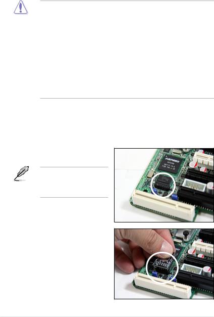
2.Place the card on the ASMB6 connector of the motherboard, aligning with the pin connectors.
2-2 |
Chapter 2: Installation |
3.Press the board firmly until it is completely seated in place.
4.When installed, the board appears as shown.
5.Insert the LAN cable plug to the LAN port for server management.
Refer to the Appendix for the location of the LAN port for server management.
6.For direct LAN configuration, connect the other end of the LAN cable to the local/central server LAN port.
For connection to a network hub or router, connect the other end of the LAN cable to the network hub or router.
7.Ensure the VGA, USB, PS/2 cables are corrected, then connect the power plug to a grounded wall socket.
Everytime after the AC power is re-plugged, you have to wait for about 60 seconds for the system power up.
ASUS ASMB6-iKVM |
2-3 |
2.3Firmware update and IP configuration
You need to update the ASMB6-iKVM firmware and configure IP source before you start using the ASMB6-iKVM board.
2.3.1Firmware update
To update the firmware:
1.Insert the support CD into the optical drive.
2.Restart the remote server, then press <Del> during POST to enter the BIOS setup.
3.Go to Boot menu and set the Boot Device Priority item to [CD-ROM].
4.When finished, press <F10> to save your changes and exit the BIOS setup.
5.On reboot, the main menu appears. Select ASMB6-iKVM Firmware Update for Preserve Configuration, and press <Enter> to enter the sub-menu.
ASUS Server Z9PE-D16 MB
FreeDOS command prompt
Configure BMC IP Source Static IP for LAN1 Configure BMC IP Source DHCP for LAN1 Configure BMC IP Source Static IP for DM_LAN1 Configure BMC IP Source DHCP for DM_LAN1
ASMB6 Firmware Update for Preserve Configuration (SDR,LAN,Username)
ASMB6 Firmware Update for Clear Configuration (SDR,LAN,Username)
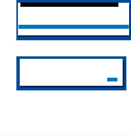
6.A confirmation message appears, asking whether you want to update the firmware or not. Select <Yes> to update.
WARNING !!!
UPDATE ASMB6 FIRMWARE NOW !
DO YOU WANT TO CONTINUE ?
No Yes
The firmware updating process starts.
2-4 |
Chapter 2: Installation |

7.When the update process is completed, the following screen appears.
NewImageSize = 32MB, offs = 0
Uploading Firmware Image : Completed
Flash Update Completed
Device Firmware has been upgraded successfully. |
|
The device will be reset within 10 seconds for the new firmware to |
|
take effect. Please wait for 70 seconds to initialize firmware. |
|
Delay |
70 seconds |
Press |
any key to continue ... |
You may update firmware from the web-based user interface. Refer to page 4-13 for details.
8.Select <Y> twice to confirm.
ASUS ASMB6-iKVM |
2-5 |

2.3.2Configure BMC IP source static IP
1.Repeat the step 1-4 in the previous sub-section.
2.On reboot, the main menu appears. Select Configure BMC IP Source Static IP for LAN1 (or DM_LAN1), and press <Enter> to enter the sub-menu.
ASUS Server Z9PE-D16 MB
FreeDOS command prompt
Configure BMC IP Source Static IP for LAN1 Configure BMC IP Source DHCP for LAN1
Configure BMC IP Source Static IP for DM_LAN1
Configure BMC IP Source DHCP for DM_LAN1
ASMB6 Firmware Update for Preserve Configuration (SDR,LAN,Username) ASMB6 Firmware Update for Clear Configuration (SDR,LAN,Username)
3.A confirmation message appears, asking if you want to configure the BMC IP source static IP now. Select <Yes> to continue.
WARNING !!!
CONFIGURE BMC IP Source STATIC IP NOW !
DO YOU WANT TO CONTINUE ?
No Yes
4.When the configuration is completed, the below screen appears.
Detect Motherboard -> (Z9PE-D16 Series)
Detect KCS Interface
New BMC IP Source : Static IP
Press any key to continue ...
5.Go to BIOS menu to set the IP. Refer to section 2.4 for IP settings in BIOS menu.
2-6 |
Chapter 2: Installation |

2.3.3Configure BMC IP source DHCP
1.Repeat the step 1-4 in the previous sub-section.
2.On reboot, the main menu appears. Select Configure BMC IP Source DHCP for LAN1 (or DM_LAN1), and press <Enter> to enter the sub-menu.
ASUS Server Z9PE-D16 MB
FreeDOS command prompt
Configure BMC IP Source Static IP for LAN1
Configure BMC IP Source DHCP for LAN1
Configure BMC IP Source Static IP for DM_LAN1 Configure BMC IP Source DHCP for DM_LAN1
ASMB6 Firmware Update for Preserve Configuration (SDR,LAN,Username)
ASMB6 Firmware Update for Clear Configuration (SDR,LAN,Username)
3.A confirmation message appears, asking if you want to configure the BMC IP source DHCP now. Select <Yes> to continue.
WARNING !!!
CONFIGURE BMC IP Source DHCP NOW !
DO YOU WANT TO CONTINUE ?
No Yes
4.When the configuration is completed, the below screen appears.
Detect |
Motherboard |
-> (Z9PE-D16 Series) |
Detect |
KCS Interface |
|
New BMC IP Source : DHCP
Press any key to continue ...
5.Then you can get IP from DHCP server.
ASUS ASMB6-iKVM |
2-7 |
2.4BIOS configuration
You need to adjust the settings in the BIOS setup of the remote server for correct configuration and connection to the central server.
• Update the remote server BIOS file following the instructions in the motherboard/system user guide. Visit the ASUS website (www.asus.com) to download the latest BIOS file for the motherboard.
•The BIOS setup screens shown in this section are for reference purposes only, and may not exactly match what you see on your screen.
2.4.1Running the BIOS BMC configuration
To configure the BMC in the BIOS:
1.Restart the remote server, then press <Del> during POST to enter the BIOS setup.
2.Go to the Server Mgmt menu, then select the BMC network configuration sub menu. Use this sub-menu to configure the BMC settings.
3.When finished, press <F10> to save your changes and exit the BIOS setup.
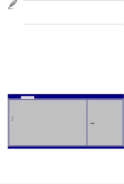
2.4.2BMC network configuration
Allows you to set the BMC LAN Parameter settings.
Aptio Setup Utility - Copyright (C) 2010 American Megatrends, Inc.
Main Server Mgmt Event Logs Advanced Monitor Boot Tool Exit
BMC Firmware Version : |
1.02 |
|
FRB-2 |
Timer timeout |
[6 minutes] |
FRB-2 |
Timer Policy |
[Reset] |
O/S Watchdog Timer |
[Disabled] |
|
O/S Wtd Timer Timeout |
[10 minutes] |
|
O/S Wtd Timer Policy |
[Reset] |
|
System Event Log |
|
|
BMC network configuration |
|
|
E n a b l e / D i s a b l e i n t e r f a c e s t o communicate with BMC.
: Select Screen
 : Select Item Enter: Select
+/—: Change Opt. F1: General Help
F9: Optimized Defaults F10: Save ESC: Exit
Version 2.01.1204. Copyright (C) 2010 American Megatrends, Inc.
2-8 |
Chapter 2: Installation |

Aptio Setup Utility - Copyright (C) 2010 American Megatrends, Inc.
Server Mgmt
BMC network configuration |
|
DM_LAN1 |
|
DM_LAN1 IP Address in BMC : |
000.000.000.000 |
DM_LAN1 Subnet Mask in BMC : |
000.000.000.000 |
DM_LAN1 Gateway Address in BMC : |
000.000.000.000 |
DM_LAN1 MAC Address in BMC : |
90.E6.BA.0A.20.BA |
Configuration source |
[Previous State] |
Lan1 |
|
Lan1 IP Address in BMC : |
000.000.000.000 |
Lan1 Subnet Mask in BMC : |
000.000.000.000 |
Lan1 Gateway Address in BMC : |
000.000.000.000 |
Lan1 MAC Address in BMC : |
90.E6.BA.0A.20.BA |
Select to configure LAN channel parameters statically or dynamically(DHCP). Do nothing option will not modify any BMC network parameters during BIOS phase.
: Select Screen
 : Select Item Enter: Select
+/—: Change Opt. F1: General Help
F9: Optimized Defaults F10: Save ESC: Exit
Configuration source |
[Previous State] |
Version 2.01.1204. Copyright (C) 2010 American Megatrends, Inc.
Configuration Source [Previous State]
Allows you to select the IP address source type. Set the LAN channel parameters statically or dynamically.
The following items are available when you set Configuration Source to [Static].
Station IP Address
Allows you to set the BMC IP address.
Subnet Mask
Allows you to set the BMC subnet mask. We recommend that you use the same
Subnet Mask you have specified on the operating system network for the used network card.
Gateway IP Address
Allows you to set the Gateway IP address.
Router MAC Address
Allows you to set the Router MAC address.
ASUS ASMB6-iKVM |
2-9 |
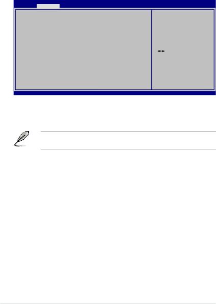
2.4.3System Event Log
Allows you to view all the events in the BMC event log. It will take a maximum of 15 seconds to read all the BMC SEL records.
Aptio Setup Utility - Copyright (C) 2010 American Megatrends, Inc.
Server Mgmt
Enabling/Disabling Options |
|
SEL Components |
[Disabled] |
Erasing Settings |
|
Erase SEL |
[No] |
When SEL is Full |
[Do Nothing] |
NOTE: All values changed here do not take effect until computer is restarted.
Select to configure LAN channel parameters statically or dynamically(DHCP). Do nothing option will not modify any BMC network parameters during BIOS phase.
: Select Screen
 : Select Item Enter: Select
+/—: Change Opt. F1: General Help
F9: Optimized Defaults F10: Save ESC: Exit
Version 2.01.1204. Copyright (C) 2010 American Megatrends, Inc.
SEL Components [Disabled]
Allows you to enable or disable all features of system event log during booting.
The following items become configurable when you set SEL Components to [Enabled].
Erase SEL [No]
Allows you to select how to erase SEL.
Configuration options: [No] [Yes, On next reset] [Yes, On every reset]
When SEL is Full [Do Nothing]
Allows you to select what to do to a full SEL.
Configuration options: [Do Nothing] [Erase Immediately]
2-10 |
Chapter 2: Installation |

2.5Running the ASMC6 utility
TheASMC6 utility allows you to update theASMB6-iKVM firmware, configure the
LAN setting for the remote server and change the user name/password in DOS environment. This utility is available from the support CD that came with the package.
To run the ASMC6 utility:
1.Insert the support CD into the optical drive.
2.Restart the remote server, then press <Del> during POST to enter the BIOS setup.
3.Go to Boot menu and set the Boot Device Priority item to [CD-ROM].
4.When finished, press <F10> to save your changes and exit the BIOS setup.
5.On reboot, the main menu appears. Select FreeDOS command prompt, and then press <Enter> .
ASUS Server Z9PE-D16 MB FreeDOS command prompt
Configure BMC IP Source Static IP for LAN1
Configure BMC IP Source DHCP for LAN1 Configure BMC IP Source Static IP for DM_LAN1 Configure BMC IP Source DHCP for DM_LAN1
ASMB6 Firmware Update for Preserve Configuration (SDR,LAN,Username) ASMB6 Firmware Update for Clear Configuration (SDR,LAN,Username)
6.When the C:> prompt appears, type ASMC6 -?, then press <Enter> to display the ASMC6 Utility Help Menu. The screen appears as shown.
+---------------------------------------------------------- |
+ |
| ASUS Server Management Card Utility 6.01 Help Menu |
| |
+---------------------------------------------------------- |
+ |
Usage: |
|
ASMC6 -kcs[smic/bt/pci_smic] NetFn command data.... |
|
ASMC6 -bmc_ip_source source[1:Static, 2:DHCP] |
|
ASMC6 -bmc_ip ip_addr[10.10.10.20] |
|
ASMC6 -bmc_mask ip_mask[255.255.255.0] |
|
ASMC6 -bmc_gateway ip_addr[10.10.10.254] |
|
ASMC6 -pet_ip_mac ip_addr[10.10.10.20] mac_addr[010203040506]
ASMC6 -bmc_ip_s_lan1 source[1:Static, 2:DHCP] ASMC6 -bmc_ip_lan1 ip_addr[10.10.10.20]
ASMC6 -bmc_mask_lan1 ip_mask[255.255.255.0]
ASMC6 -bmc_g_lan1 ip_addr[10.10.10.254]
ASMC6 -pet_ip_m_lan1 ip_addr[10.10.10.20] mac_addr[010203040506] ASMC6 -adm_name new_name_string
ASMC6 -user_name new_name_string
ASMC6 -adm_password new_adm_password
ASMC6 -user_password new_user_password
<Press any key to see the next page> <ESC key to break>
Press any key to see next page.
ASUS ASMB6-iKVM |
2-11 |

<Press any key to see the next page> <ESC key to break>
ASMC6 -sol_baud 57600[9600/19200/38400/57600/115200]
ASMC6 -bmc_info
ASMC6 -fru -view fru_id ASMC6 -fru -load fru_file
ASMC6 -fru -save fru_id ru_file ASMC6 -sel -clear
C:\>
ASMC6 Help Menu options
Options
-kcs[smic/bt/pci_smic] NetFn command data....
-bmc_ip_source source[1: Static, 2: DHCP]
-bmc_ip [ip_addr]
(e.g., bmc_ip 10.10.10.20)
-bmc_mask [ip_mask]
(e.g., bmc_mask 255.255.255.0)
-bmc_gateway [ip_addr]
(e.g., bmc_gateway 10.10.10.254)
-pet_ip_mac [ip_addr] [mac_addr]
(e.g., pet_ip_mac 10.10.10.20 010203040506)
-bmc_ip_s_lan1 source[1: Static, 2: DHCP]
-bmc_ip_lan1 [ip_addr] (e.g., bmc_ip 10.10.10.20)
-bmc_mask_lan1 [ip_mask] (e.g., bmc_mask 255.255.255.0)
-bmc_g_lan1 [ip_addr]
(e.g., bmc_gateway 10.10.10.254)
-pet_ip_m_lan1 [ip_addr] [mac_addr]
(e.g., pet_ip_mac 10.10.10.20 010203040506)
-adm_name new_name_string
-user_name new_name_string
-adm_password new_adm_password
-user_password new_user_password
-sol_baud [baud rate] (e.g., sol_baud 57600)
-bmc_info
-fru -view fru_id
-fru -load fru_file
-fru -save fru_id fru_file
-sel -clear
Description
Send IPMI command
Set the IP source
Write the BMC IP address for dedicated LAN
Write the subnet mask for dedicated LAN
Write the gateway address for dedicated LAN
Write the PET destination IP and MAC addresses for dedicated LAN
Set the IP source for shared LAN
Write the BMC IP address for shared LAN
Write the subnet mask for shared LAN
Write the gateway address for shared LAN
Write the PET destination IP and MAC addresses for shared LAN
Change the administration name
Change the user name
Change the administration password
Change the user password
Set the communication Baud rate
Displays the BMC and PET IP and MAC addresses
Displays the system FRU information
Update system FRU data from file
Save system FRU data to file
Clear system event log
2-12 |
Chapter 2: Installation |
 Loading...