


 AP1600R-E2
(AA2/AI2)
1U Rackmount Barebone Server
User Guide

E1962
First Edition V1
August 2005
Copyright © 2005 ASUSTeK COMPUTER INC. All Rights Reserved.
No part of this manual, including the products and software described in it, may be reproduced, transmitted, transcribed, stored in a retrieval system, or translated into any language in any form or by any means, except documentation kept by the purchaser for backup purposes, without the express written permission of ASUSTeK COMPUTER INC. (“ASUS”).
ASUS provides this manual “as is” without warranty of any kind, either express or implied, including but not limited to the implied warranties or conditions of merchantability or fitness for a particular purpose. In no event shall ASUS, its directors, officers, employees, or agents be liable for any indirect, special, incidental, or consequential damages (including damages for loss of profits, loss of business, loss of use or data, interruption of business and the like), even if ASUS has been advised of the possibility of such damages arising from any defect or error in this manual or product.
Specifications and information contained in this manual ae furnished for informational use only, and are subject to change at any time without notice, and should not be construed as a commitment by ASUS. ASUS assumes no responsibility or liability for any errors or inaccuracies that may appear in this manual, including the products and software described in it.
Product warranty or service will not be extended if: (1) the product is repaired, modified or altered, unless such repair, modification of alteration is authorized in writing by ASUS; or (2) the serial number of the product is defaced or missing.
Products and corporate names appearing in this manual may or may not be registered trademarks or copyrights of their respective companies, and are used only for identification or explanation and to the owners’ benefit, without intent to infringe.
ii

Contents
Notices ............................................................................................... |
vii |
Safety information ............................................................................ |
viii |
About this guide ................................................................................. |
ix |
Chapter 1: Product introduction ....................... |
1-1 |
||
1.1 |
System package contents .................................................... |
1-2 |
|
1.2 |
System specifications .......................................................... |
1-3 |
|
1.3 |
Front panel features ............................................................. |
1-4 |
|
1.4 |
Rear panel features .............................................................. |
1-5 |
|
1.5 |
Internal features ................................................................... |
1-6 |
|
1.6 |
LED information .................................................................... |
1-7 |
|
|
1.6.1 |
Front panel LEDs .................................................... |
1-7 |
|
1.6.2 |
Rear panel LEDs ...................................................... |
1-7 |
Chapter 2: Hardware setup .............................. |
2-1 |
||
2.1 |
Chassis cover ....................................................................... |
2-2 |
|
|
2.1.1 |
Removing the cover................................................ |
2-2 |
|
2.1.2 |
Installing the cover ................................................. |
2-3 |
2.2 |
Central Processing Unit (CPU) .............................................. |
2-4 |
|
|
2.2.1 |
Installling a CPU ...................................................... |
2-4 |
|
2.2.2 Installing the CPU heatsink ..................................... |
2-6 |
|
2.4 |
System memory ................................................................... |
2-7 |
|
|
2.4.1 |
Overview ................................................................. |
2-7 |
|
2.4.2 |
Memory configurations ........................................... |
2-7 |
|
2.4.4 |
Removing a DIMM ................................................... |
2-8 |
|
2.4.3 |
Installing a DIMM ..................................................... |
2-8 |
2.4 |
Hard disk drives .................................................................... |
2-9 |
|
|
2.4.1 Installing a hot-swap SATA HDD (AA2 model) ....... |
2-9 |
|
|
2.4.2 Installing an IDE HDD (AI2 model) ........................ |
2-11 |
|
|
2.4.3 Installing an internal SATA HDD (AI2 model) ....... |
2-13 |
|
2.5 |
Expansion slot .................................................................... |
2-14 |
|
|
2.5.1 Installing an expansion card .................................. |
2-14 |
|
|
2.5.2 Configuring an expansion card.............................. |
2-16 |
|
2.6 |
Cable connections .............................................................. |
2-17 |
|
2.7 |
Removable components ..................................................... |
2-19 |
|
|
2.7.1 |
System fans .......................................................... |
2-19 |
|
2.7.2 |
Device fan ............................................................. |
2-19 |
iii

|
2.7.3 |
Power supply module ............................................ |
2-20 |
|
2.7.4 |
Optical drive ......................................................... |
2-21 |
|
2.7.5 |
Motherboard ......................................................... |
2-23 |
2.8 |
SATA backplane cabling (for AA2) .................................... |
2-26 |
|
2.9 |
Fan control board cabling (for AI2) .................................... |
2-27 |
|
Chapter 3: Installation options ......................... |
3-1 |
|
3.1 |
Rackmount rail kit items ....................................................... |
3-2 |
3.2 |
Rack rails assembly .............................................................. |
3-2 |
3.3 |
Attaching the rails to the rack ............................................. |
3-3 |
3.4 |
Rackmounting the server ..................................................... |
3-4 |
Chapter 4: Motherboard information ................. |
4-1 |
|
4.1 |
Motherboard layout .............................................................. |
4-2 |
4.2 |
Jumpers ................................................................................ |
4-5 |
4.3 |
Connectors ......................................................................... |
4-10 |
Chapter 5: BIOS SETUP .................................... |
5-1 |
||
5.1 Managing and updating your BIOS ........................................ |
5-2 |
||
|
5.1.1 Creating a bootable floppy disk .............................. |
5-2 |
|
|
5.1.2 |
AwardBIOS Flash Utility .......................................... |
5-4 |
|
5.1.3 ASUS CrashFree BIOS 2 utility ................................ |
5-8 |
|
|
5.1.4 ASUS EZ Flash utility ............................................ |
5-10 |
|
|
5.1.5 |
ASUS Update utility .............................................. |
5-11 |
5.2 |
BIOS Setup program ........................................................... |
5-14 |
|
|
5.2.1 |
BIOS menu screen ................................................. |
5-15 |
|
5.2.2 |
Menu bar ............................................................... |
5-15 |
|
5.2.3 |
Navigation keys .................................................... |
5-15 |
|
5.2.4 |
General help .......................................................... |
5-16 |
|
5.2.5 |
Sub-menu ............................................................. |
5-16 |
|
5.2.6 |
Scroll bar .............................................................. |
5-16 |
|
5.2.7 |
Pop-up window ..................................................... |
5-16 |
5.3 |
Main menu .......................................................................... |
5-17 |
|
|
5.3.1 |
Primary IDE Master ............................................... |
5-18 |
|
5.3.2 |
Primary IDE Slave .................................................. |
5-20 |
|
5.3.3 |
Secondary IDE Master ........................................... |
5-20 |
|
5.3.4 |
Secondary IDE Slave ............................................. |
5-20 |
iv

5.4 |
Advanced menu .................................................................. |
5-21 |
|
|
5.4.1 |
Advanced BIOS Features ...................................... |
5-22 |
|
5.4.2 |
CPU Configuration................................................. |
5-23 |
|
5.4.3 |
Memory Configuration .......................................... |
5-24 |
|
5.4.4 |
Chipset ................................................................. |
5-25 |
|
5.4.5 |
Onboard Device .................................................... |
5-26 |
|
5.4.6 |
PCIPnP ................................................................... |
5-30 |
|
5.4.7 |
USB Configuration................................................. |
5-32 |
5.5 |
Power menu ........................................................................ |
5-33 |
|
|
5.5.1 |
APM Configuration ................................................ |
5-34 |
|
5.5.2 |
Hardware Monitor ................................................. |
5-37 |
5.6 |
Boot menu .......................................................................... |
5-39 |
|
|
5.6.1 |
Boot Device Priority.............................................. |
5-39 |
|
5.6.2 Hard Disk Boot Priority ......................................... |
5-40 |
|
|
5.6.3 |
Removable Device Priority .................................... |
5-40 |
|
5.6.4 |
CD-ROM Boot Priority ........................................... |
5-41 |
|
5.6.5 |
Boot Settings Configuration ................................. |
5-41 |
|
5.6.6 |
Security ................................................................ |
5-43 |
5.7 |
Exit menu ........................................................................... |
5-45 |
|
Chapter 6: Driver installation ........................... |
6-1 |
|
6.1 RAID ...................................................................................... |
|
6-2 |
6.1.1 |
RAID configurations ................................................ |
6-2 |
6.1.2 Installing hard disk drives ....................................... |
6-2 |
|
6.1.3 Setting the RAID item in BIOS ................................ |
6-3 |
|
6.1.4 |
RAID configuration utility........................................ |
6-3 |
6.1.5 Creating a RAID driver disk ................................... |
6-21 |
|
6.1.6Installing the Intel® 6300ESB RAID controller
|
|
driver .................................................................... |
6-22 |
6.2 |
LAN .................................................................................... |
|
6-29 |
|
6.2.1 |
Windows® 2000 Server ....................................... |
6-29 |
|
6.2.2 |
Windows® 2003 Server ....................................... |
6-31 |
|
6.2.3 Red Hat® Linux 9.0 .............................................. |
6-33 |
|
6.3 |
VGA .................................................................................... |
|
6-34 |
|
6.3.1 |
Windows® 2000 Server ....................................... |
6-34 |
|
6.3.2 |
Windows® 2003 Server ....................................... |
6-35 |
|
6.3.3 Red Hat® Linux 9.0 .............................................. |
6-35 |
|
v

Notices
Federal Communications Commission Statement
This device complies with Part 15 of the FCC Rules. Operation is subject to the following two conditions:
•This device may not cause harmful interference, and
•This device must accept any interference received including interference that may cause undesired operation.
This equipment has been tested and found to comply with the limits for a Class A digital device, pursuant to Part 15 of the FCC Rules. These limits are designed to provide reasonable protection against harmful interference in a residential installation. This equipment generates, uses and can radiate radio frequency energy and, if not installed and used in accordance with manufacturer’s instructions, may cause harmful interference to radio communications. However, there is no guarantee that interference will not occur in a particular installation. If this equipment does cause harmful interference to radio or television reception, which can be determined by turning the equipment off and on, the user is encouraged to try to correct the interference by one or more of the following measures:
•Reorient or relocate the receiving antenna.
•Increase the separation between the equipment and receiver.
•Connect the equipment to an outlet on a circuit different from that to which the receiver is connected.
•Consult the dealer or an experienced radio/TV technician for help.
WARNING! The use of shielded cables for connection of the monitor to the graphics card is required to assure compliance with FCC regulations. Changes or modifications to this unit not expressly approved by the party responsible for compliance could void the user’s authority to operate this equipment.
Canadian Department of Communications Statement
This digital apparatus does not exceed the Class A limits for radio noise emissions from digital apparatus set out in the Radio Interference Regulations of the Canadian Department of Communications.
This Class A digital apparatus complies with Canadian ICES-003.
vi
Safety information
Electrical Safety
•Before installing or removing signal cables, ensure that the power cables for the system unit and all attached devices are unplugged.
•To prevent electrical shock hazard, disconnect the power cable from the electrical outlet before relocating the system.
•When adding or removing any additional devices to or from the system, ensure that the power cables for the devices are unplugged before the signal cables are connected. If possible, disconnect all power cables from the existing system before you add a device.
•If the power supply is broken, do not try to fix it by yourself. Contact a qualified service technician or your dealer.
Operation Safety
•Any mechanical operation on this server must be conducted by certified or experienced engineers.
•Before operating the server, carefully read all the manuals included with the server package.
•Before using the server, make sure all cables are correctly connected and the power cables are not damaged. If any damage is detected, contact your dealer as soon as possible.
•To avoid short circuits, keep paper clips, screws, and staples away from connectors, slots, sockets and circuitry.
•Avoid dust, humidity, and temperature extremes. Place the server on a stable surface.
This product is equipped with a three-wire power cable and plug for the user’s safety. Use the power cable with a properly grounded electrical outlet to avoid electrical shock.
 Lithium-Ion Battery Warning
  CAUTION! Danger of explosion if battery is incorrectly replaced. Replace only with the same or equivalent type recommended by the manufacturer. Dispose of used batteries according to the manufacturer’s instructions.
 CD-ROM Drive Safety Warning
CLASS 1 LASER PRODUCT
Heavy System
CAUTION! This server system is heavy. Ask for assistance when moving or carrying the system.
vii

About this guide
Audience
This user guide is intended for system integrators, and experienced users with at least basic knowledge of configuring a server.
Contents
This guide contains the following parts:
1 . Chapter 1: Product Introduction
This chapter describes the general features of the server, including sections on front panel and rear panel specifications.
2 . Chapter 2: Hardware setup
This chapter lists the hardware setup procedures that you have to perform when installing or removing system components.
3 . Chapter 3: Installation options
This chapter describes how to install optional components into the barebone server.
4 . Chapter 4: Motherboard information
This chapter gives information about the motherboard that comes with the server. This chapter includes the motherboard layout, jumper settings, and connector locations.
5 . Chapter 5: BIOS information
This chapter tells how to change system settings through the BIOS Setup menus and describes the BIOS parameters.
6 . Chapter 6: Driver installation
This chapter provides instructions for creating and configuring RAID, and installing the necessary drivers for different system components.
viii

Conventions
To make sure that you perform certain tasks properly, take note of the following symbols used throughout this manual.
WARNING: Information to prevent injury to yourself when trying to complete a task.
CAUTION: Information to prevent damage to the components when trying to complete a task.
IMPORTANT: Instructions that you MUST follow to complete a task.
NOTE: Tips and information to aid in completing a task.
References
Refer to the following sources for additional information, and for product and software updates.
1 . ASUS NCCH-DR motherboard user guide
This manual contains detailed information about the ASUS NCCH-DR motherboard.
2 . ASUS Server Web-based Management (ASWM) user guide
This manual tells how to set up and use the proprietary ASUS server management utility.
3 . ASUS websites
The ASUS websites worldwide provide updated information for all ASUS hardware and software products. Refer to the ASUS contact information.
ix

x
Chapter 1
This chapter describes the general features of the chassis kit. It includes sections on front panel and rear panel specifications.
ASUS AP1600R-E2 (AA2/AI2)
Product introduction
1-1

1.1System package contents
The items in the ASUS AP1600R-E2 (AA2/AI2) product package vary depending on the model your purchased. Check your package for the standard items listed in the following table.
Package items |
AA2 model |
AI2 model |
|
|
|
ASUS AR14 1U rackmount chassis with:
• ASUS NCCH-DR motherboard
• 500W power supply
• SATA backplane
• Fan control board
• Optical drive
• System fan
• Device fan
• 2 x internal HDD trays
• 2 x hot-swap HDD trays
• Pre-connected device/power cables
CPU heatsink
SATA cable
IDE cable
Rackmount rail kit
Bundled CDs
• AP1600R-E2 drivers and utilities CD
• CA Anti-virus software CD
User guide
*AA2 model - supports up to two hot-swap SATA hard disks
*AI2 model - supports up to two internal IDE hard disks,
or up to two internal SATA hard disks
Contact your dealer immediately if any of the items is damaged or missing.
1 - 2 |
Chapter 1: Product introduction |

1.2System specifications
The ASUS AP1600R-E2 (AA2/AI2) is a 1U barebone server system featuring the ASUS NCCH-DR motherboard. The server supports dual Intel® Xeon™ processors, and includes the latest technologies through the chipsets embedded on the motherboard.
|
Chassis |
Rackmount 1U (AR14) |
|
Motherboard |
ASUS NCCH-DR |
|
Chipset |
North Bridge: Intel® E7210 Memory Controller Hub (MCH) |
|
|
South Bridge: Intel® 6300ESB |
|
Processor |
Supports dual Intel® Xeon™ 3.4+GHz processors with Hyper- |
|
|
Threading Technology via two 604-pin sockets |
|
Memory |
4 x 184-pin DDR sockets for up to 8 GB system memory |
|
|
Supports PC3200/PC2700 unbuffered ECC or non-ECC DIMMs |
|
|
Supports dual-channel memory architecture |
|
L A N |
Intel® PRO/1000 CT Network Connection (82547GI) |
|
|
Intel® PRO/1000 MT Network Connection (82541GI) |
|
V G A |
ATI RAGE-XL PCI-based VGA controller |
|
|
Supports 8MB display memory |
|
Expansion slots |
1 x PCI-X 66 MHz/64-bit slot (PCI-X 1.0) |
|
|
1 x Mini-PCI socket for the ASUS Server Management Board |
|
Storage |
Intel® 6300ESB South Bridge supports: |
|
|
- 2 x Ultra DMA 100/66/33 HDDs (ID E model) |
|
|
- 2 x SATA HDDs with RAID 0/1 configuration and |
|
|
Intel® Matrix Storage Technology (SATA model) |
|
Management |
ASUS Server Web-based Management (ASWM) |
|
Hardware monitors |
Voltage, temperature, and fan speed monitoring |
|
|
Automatic System Restart (ASR) feature |
|
Power supply |
500W power supply, 115V~230V, 50Hz~60Hz |
|
Dimensions |
600 mm (l) x 445 mm (w) x 43.6 mm (h)) |
|
|
|
ASUS AP1600R-E2 (AA2/AI2) |
1 - 3 |
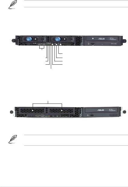
1.3Front panel features
The barebone server displays a simple yet stylish front panel with easily accessible features. The power and reset buttons, LED indicators, location switch, optical drive, and two USB ports are located on the front panel.
Refer to section “1.6.1 Front panel LEDs” for the LED descriptions.
AA2 model
Rac k screw |
Hot-swap HDD bays |
Optical drive |
Rac k screw |
|||||
|
|
|
|
|
|
|
|
|
|
|
|
|
|
|
|
|
|
|
|
|
|
|
|
|
|
|
|
|
|
|
|
|
|
|
|
US B ports
HDD Access LED
LAN 2 LED
LAN 1 LED
Message LED
 Power button Powe r LED Location switch Location LED Reset button
AI2 model
Internal HDD bays
The AA2 and AI2 models have the same front panel features except for the HDD bays.
1 - 4 |
Chapter 1: Product introduction |
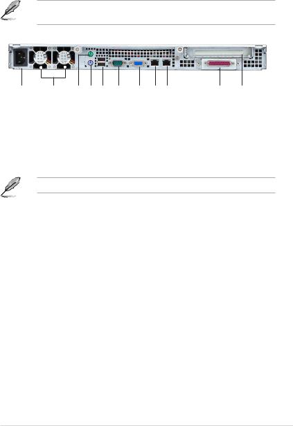
1.4Rear panel features
The rear panel includes the expansion slot, system power socket, and rear fans. The middle part includes the I/O shield with openings for the rear panel connectors on the motherboard.
The ports for the PS/2 keyboard, PS/2 mouse, USB, VGA, and Gigabit LAN do not appear on the rear panel if motherboard is not present.
CA |
eR |
p |
ra |
wo |
af |
re |
sn |
tekcos |
|
PS/ 2 |
PS/ 2 |
mo use |
ke yb oa |
po |
rd |
rt |
po |
|
rt |
BSU |
ireS |
AGV |
strop |
rop la |
trop |
|
t |
|
LAN |
LAN |
po rt1 |
po rt2 |
Par all e |
Exp an s |
li
po |
on |
tsl
otr
Refer to section “1.6.2 Rear panel LEDs” for the LED descriptions.
ASUS AP1600R-E2 (AA2/AI2) |
1 - 5 |
, AP1600R-E2(AI2) Manual")
1.5Internal features
The barebone server includes the basic components as shown.
The AA2 and AI2 models have the same internal features except for the SATA backplane, fan control board, and HDD trays.
|
AA2 model |
|
AI2 model |
|
|
2 |
|
|
1 |
|
|
|
3 |
4 |
|
|
|
|
|
5 |
6 |
|
|
|
7 |
|
7 |
|
|
10 |
|
8 |
9 |
8 |
9 |
1.PCI-X riser card bracket
2.Rear fans
3.ASUS NCCH-DR motherboard
4.Power supply
5.Device fan
6.System fans
7.AA2: SATA backplane AI2: Fan control board
8.AA2: Hot-swap HDD tray 1 AI2: Internal HDD tray 1
9.AA2: Hot-swap HDD tray 2 AI2: Internal HDD tray 2
10. Optical drive
The barebone server does not include a floppy disk drive. Connect an external floppy disk drive (USB interface) to any of the USB ports on the front or rear panel if you need to use a floppy disk.
1 - 6 |
Chapter 1: Product introduction |

1.6LED information
1.6.1Front panel LEDs
|
|
|
|
|
|
|
|
|
|
|
|
|
|
|
|
|
|
|
|
|
|
|
|
HDD Access LED |
|
|
|
Powe r LED |
||||
|
|
|
|
|
|
|
Location LED |
|||
|
|
LAN 2 LED |
|
|||||||
|
|
Message LED |
||||||||
|
|
|
|
|
|
|||||
|
|
|
LAN 1 LED |
|
|
|
|
|
||
|
|
|
|
|
|
|||||
|
L E D |
Display status |
Description |
|||||||
|
Power LED |
ON |
System power ON |
|||||||
|
HDD Access LED |
OFF |
No activity |
|||||||
|
|
Blinking |
Read/write data into the HDD |
|||||||
|
Message LED |
OFF |
System is normal; no incoming event |
|||||||
|
|
Blinking |
ASWM indicates a HW monitor event |
|||||||
|
Location LED |
OFF |
Normal status |
|||||||
|
|
ON |
Location switch is pressed |
|||||||
|
|
|
|
|
|
(Press the location switch again to turn off) |
||||
|
LAN LEDs |
OFF |
No LAN connection |
|||||||
|
|
Blinking |
LAN is transmitting or receiving data |
|||||||
|
|
ON |
LAN connection is present |
|||||||
|
|
|
|
|
|
|
|
|
|
|
1.6.2Rear panel LEDs
RJ-45
ACT/LNK |
SPEED |
ACT/LINK LED |
|
SPEE D LED |
|
||
Status |
Description |
Status |
|
Description |
|
OFF |
No link |
OFF |
|
10Mbps connection |
|
Green |
Linked |
Orange |
|
100Mbps connection |
|
Blinking |
Linking |
Green |
|
1000Mbps connection |
|
|
|
|
|
|
|
ASUS AP1600R-E2 (AA2/AI2) |
1 - 7 |

1 - 8 |
Chapter 1: Product introduction |

Chapter 2
This chapter lists the hardware setup procedures that you have to perform when installing or removing system components.
ASUS AP1600R-E2 (AA2/AI2)
Hardware setup
2-1
2.1Chassis cover
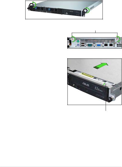
2.1.1Removing the cover
1.Use a Phillips screwdriver to remove the screw on each front end of the top cover.
Thumbscrews
2.Loosen the two thumbscrews on the rear panel to release the top cover from the chassis.
3.Firmly hold the cover and slide it toward the rear panel for about half an inch until it is disengaged from the chassis.
1/2 inch distance
4.Lift the cover from the chassis.
2 - 2 |
Chapter 2: Hardware setup |
2.1.2Installing the cover
1.Position the cover on top of the chassis with the thumbscrews on the rear, and leaving a gap of about half an inch from the front panel.
Side markings
2.Make sure that the side markings on the cover (two on each side) are aligned to the grooves on the chassis.
Grooves
3.Slide the cover toward the front until it snaps in place.
4.Tighten the thumbscrews on the rear to secure the cover.
Thumbscrews
ASUS AP1600R-E2 (AA2/AI2) |
2 - 3 |
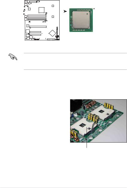
2.2Central Processing Unit (CPU)
The motherboard comes with two surface mount 604-pin Zero Insertion Force (ZIF) socket and designed for the Intel® Xeon™ processors.
|
|
|
|
|
|
|
|
|
|
|
|
|
|
|
|
|
|
|
|
|
|
|
|
|
|
|
|
|
Intel Xeon |
||
|
|
|
|
|
|
|
|
|
|
|
|
|
|
|
|
|
|
|
|
|
|
|
|
|
|
|
|
|
|||
|
|
|
|
|
|
|
|
|
|
|
|
|
|
|
|
|
|
|
|
|
|
|
|
|
|
||||||
|
|
|
|
|
|
|
|
|
|
|
|
|
|
|
|
|
|
|
|
|
|
|
|
|
|
|
|
|
|
|
Gold Arrow |
|
|
|
|
|
|
|
|
|
|
|
|
|
|
|
|
|
|
|
|
|
|
|
|
CPU2 |
|
|
|
|
|
Pin A1 |
|
|
|
|
|
|
|
|
|
|
|
|
|
|
|
|
|
|
|
|
|
|
|
|
|
|
|
|
|
|
|
|
|
|
|
|
|
|
|
|
|
|
|
|
|
|
|
|
|
|
|
|
|
|
|
|
|
|
|
|
|
|
|
|
|
|
|
|
|
|
|
|
|
|
|
|
|
|
|
|
|
|
|
|
|
|
|
|
|
|
|
|
|
|
|
|
|
|
|
|
|
|
|
|
|
|
|
|
|
|
|
|
|
|
|
|
|
|
|
|
|
|
|
|
|
|
|
|
|
|
|
|
|
|
|
|
|
|
|
|
|
|
|
|
|
|
|
|
|
|
|
|
|
|
|
|
|
|
|
|
|
|
|
|
|
|
|
|
|
|
|
|
|
|
|
|
|
|
|
|
|
|
|
|
|
CPU1 |
|
|
|
|
|
|
|
|
|
|
|
|
|
|
|
|
|
|
|
|
|
|
|
|
|
|
|
|
|
|
|
|
|
|
|
|
|
|
|
|
|
|
|
|
|
|
|
|
|
|
|
|
|
|
|
|
|
|
|
|
|
|
|
|
|
|
|
|
|
|
|
|
|
|
|
|
|
|
|
|
|
|
|
|
|
|
|
|
|
|
|
|
|
|
|
|
|
|
|
|
|
|
|
|
|
|
|
|
|
|
|
|
|
|
|
|
|
|
|
|
|
|
|
|
|
|
|
|
|
|
|
|
|
|
|
|
|
|
|
|
|
|
|
|
|
|
|
|
|
|
|
|
|
|
|
|
|
|
|
|
|
|
|
|
|
|
|
NCCH-DR
NCCH-DR CPU Socket 604
1.The motherboard supports either one or two CPUs. If you are installing only one CPU, you MUST install it in CPU socket 1.
2.If you are installing two CPUs, install in the CPU socket 2 first.
2.2.1Installling a CPU
To install the CPUs:
1.Locate the CPU sockets on the motherboard. Flip up the socket lever and push it all the way to the other side.
Socket for CPU1
2 - 4 |
Chapter 2: Hardware setup |

2.Carefully insert the CPU into the socket as shown until it fits in place.
The CPU fits only in one correct orientation. DO NOT force the CPU into the socket to prevent bending the pins and damaging the CPU!
3.Carefully push down the socket lever to secure the CPU. The lever clicks on the side tab to indicate that it is locked.
4.Apply the thermal interface material (thermal grease) to the top of the CPU. This thermal grease should come with the CPU package.
5.Repeat steps 1 to 4 if you wish to install a second CPU.
Marked corner (gold arrow)
ASUS AP1600R-E2 (AA2/AI2) |
2 - 5 |

2.2.2Installing the CPU heatsink
To install the CPU heatsink:
1.Carefully place the heatsink on top of the installed CPU.
2.Twist each of the four screws with a Philips (cross) screwdriver just enough to attach the heatsink to the motherboard. When the four screws are attached, tighten them one by one to completely secure the heatsink.
3.Follow steps 1 and 2 to install the second CPU heatsink.
2 - 6 |
Chapter 2: Hardware setup |

2.4System memory
2.4.1Overview
The motherboard comes with four Double Data Rate (DDR) Dual Inline Memory Modules (DIMM) sockets.
|
|
|
|
|
|
|
|
104 Pins |
80 Pins |
||
|
|
|
|||||||||
|
|
|
|
|
|
|
|
|
|
|
|
|
|
|
|
|
|
|
|
|
|
|
|
|
|
|
|
|
|
|
|
|
|
|
|
|
|
|
|
|
|
|
|
|
|
|
|
|
|
|
|
|
|
|
|
|
|
|
|
|
|
|
|
|
|
|
|
|
|
|
|
|
|
|
|
|
|
|
|
|
|
|
|
DIMM_A1
DIMM_A2
DIMM_B1
NCCH-DR
DIMM_B2
NCCH-DR 184-Pin DDR DIMM sockets
2.4.2Memory configurations
You may install 128 MB, 256 MB, 512 MB, 1 GB, and 2 GB unbuffered ECC or non-ECC DDR DIMMs into the DIMM sockets.
• Always install DIMMs with the same CAS latency. For optimum compatibility, it is recommended that you obtain memory modules from the same vendor. Refer to the DDR Qualified Vendors List on the ASUS website for details.
•Due to chipset resource allocation, the system may detect less than 8 GB system memory when you install four 2 GB DDR memory modules.
•This motherboard does not support memory modules made up of 128 Mb chips or double sided x16 memory modules.
•Three DDR DIMMs intalled into any three memory sockets will function in single-channel mode.
ASUS AP1600R-E2 (AA2/AI2) |
2 - 7 |

2.4.3Installing a DIMM
Make sure to unplug the power supply before adding or removing DIMMs or other system components. Failure to do so may cause severe damage to both the motherboard and the components.
1.Unlock a DIMM socket by pressing the retaining clips outward.
2.Align a DIMM on the socket such
that the notch on the DIMM matches the break on the
socket. 1
2
DDR DIMM notch
1
Unlocked retaining clip
A DDR DIMM is keyed with a notch so that it fits in only one direction. DO NOT force a DIMM into a socket to avoid damaging the DIMM.
3.Firmly insert the DIMM into the socket until the retaining clips snap back in place and the DIMM is properly seated.
Locked Retaining Clip
2.4.4Removing a DIMM
Follow these steps to remove a DIMM.
1.Simultaneously press the retaining clips outward to unlock the DIMM.
2
1
1 |
DDR DIMM notch |
|
Support the DIMM lightly with your fingers when pressing the retaining clips. The DIMM might get damaged when it flips out with extra force.
2.Remove the DIMM from the socket.
2 - 8 |
Chapter 2: Hardware setup |
2.4Hard disk drives
2.4.1Installing a hot-swap SATA HDD (AA2 model)
To install a hot-swap SATA HDD:
1.Release a drive tray by pushing the spring lock to the right, then pulling the tray lever outward. The drive tray ejects slightly after you pull out the lever.
2.Firmly hold the tray lever and pull the drive tray out of the bay.
3.Take note of the drive tray holes. Each side has three holes to fit different types of hard disk drives. Use two screws on each side to secure the hard disk drive.
4.Place a SATA hard disk drive on the tray, then secure it with four screws.
ASUS AP1600R-E2 (AA2/AI2) |
2 - 9 |
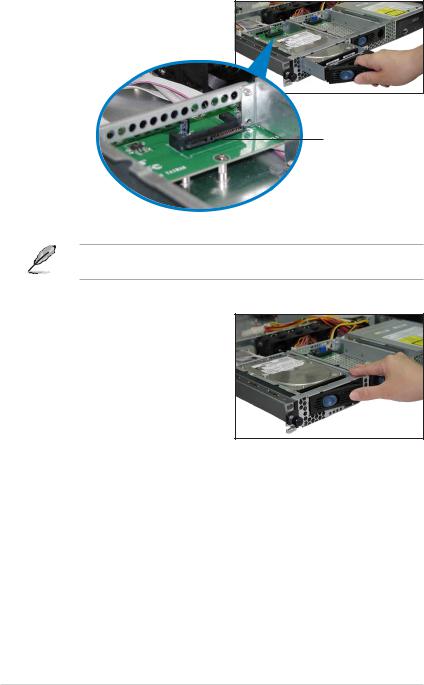
5.Carefully insert the drive tray and push it all the way to the depth of the bay until just a small fraction of the tray edge protrudes.
SATA interface on the backplane
When installed, the SATA connector on the drive connects to the SATA interface on the backplane.
6.Push the tray lever until it clicks, and secures the drive tray in place. The drive tray is correctly placed when its front edge aligns with the bay edge.
7.Repeat steps 1 to 6 if you wish to install a second SATA drive.
8.Connect the bundled SATA cables to the connectors on the SATA backplane. Refer to section “2.7 SATA backplane cabling” for information on the SATA backplane cable connections.
2 - 10 |
Chapter 2: Hardware setup |
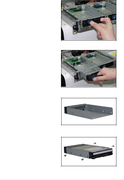
2.4.2Installing an IDE HDD (AI2 model)
To install an IDE HDD:
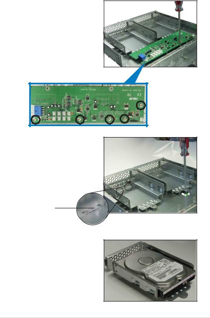
1.Disconnect all the cables from the fan control board. Use a Phillips (cross) screwdriver to remove the five screws that secure the fan control board.
Fan control board screws
2.Remove the screw that secures the hard disk tray to the chassis. Slide the tray backward until the two tray lock tabs are disengaged. Lift the tray from the bay.
Lock tab
3.Place a hard disk drive on the drive tray, and secure it with four screws.
ASUS AP1600R-E2 (AA2/AI2) |
2 - 11 |
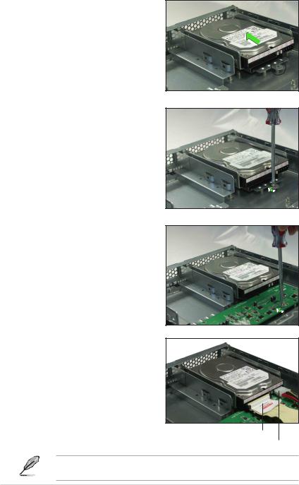
4.Carefully place the tray with installed hard disk drive into the drive bay. Slide it forward until the front end aligns with the front panel, and the screw hole matches the standoff.
5.Secure the tray with a screw.
6.Repeat steps 2 to 5 if you wish to install a second HDD; otherwise, proceed to step 7.
7.Reinstall the fan control board. Secure the board with five screws.
8.Connect the 40-pin IDE cable and a 4-pin power plug to their respective connectors on the back of the drive.
40-pin IDE cable
4-pin power plug
The other end of the IDE cable is pre-connected to the primary IDE connector on the motherboard.
2 - 12 |
Chapter 2: Hardware setup |
 Loading...