


Version 1.0
Published October 2019
Copyright©2019 ASRock INC. All rights reserved.
Copyright Notice:
No part of this documentation may be reproduced, transcribed, transmitted, or translated in any language, in any form or by any means, except duplication of documentation by the purchaser for backup purpose, without written consent of ASRock Inc.
Products and corporate names appearing in this documentation may or may not be registered trademarks or copyrights of their respective companies, and are used only for identification or explanation and to the owners’ benefit, without intent to
infringe.
Disclaimer:
Specifications and information contained in this documentation are furnished for informational use only and subject to change without notice, and should not be constructed as a commitment by ASRock. ASRock assumes no responsibility for any errors or omissions that may appear in this documentation.
With respect to the contents of this documentation, ASRock does not provide warranty of any kind, either expressed or implied, including but not limited to the implied warranties or conditions of merchantability or fitness for a particular purpose.
In no event shall ASRock, its directors, officers, employees, or agents be liable for any indirect, special, incidental, or consequential damages (including damages for loss of profits, loss of business, loss of data, interruption of business and the like), even if ASRock has been advised of the possibility of such damages arising from any defect or error in the documentation or product.
This device complies with Part 15 of the FCC Rules. Operation is subject to the following two conditions:
(1)this device may not cause harmful interference, and
(2)this device must accept any interference received, including interference that may cause undesired operation.
CALIFORNIA, USA ONLY
The Lithium battery adopted on this motherboard contains Perchlorate, a toxic substance controlled in Perchlorate Best Management Practices (BMP) regulations passed by the California Legislature. When you discard the Lithium battery in California, USA, please follow the related regulations in advance.
“Perchlorate Material-special handling may apply, see www.dtsc.ca.gov/hazardouswaste/ perchlorate”
ASRock Website: http://www.asrock.com

AUSTRALIA ONLY
Our goods come with guarantees that cannot be excluded under the Australian Consumer Law. You are entitled to a replacement or refund for a major failure and compensation for any other reasonably foreseeable loss or damage caused by our goods. You are also entitled to have the goods repaired or replaced if the goods fail to be of acceptable quality and the failure does not amount to a major failure. If you require assistance please call ASRock Tel : +886-2-28965588 ext.123 (Standard International call charges apply)
Manufactured under license under U.S. Patent Nos: 5,956,674; 5,974,380; 6,487,535; 7,003,467 & other U.S. and worldwide patents issued & pending. DTS, the Symbol, & DTS and the Symbol together is a registered trademark & DTS Connect, DTS Interactive, DTS Neo:PC are trademarks of DTS, Inc. Product includes software.
© DTS, Inc., All Rights Reserved.
CE Warning
This device complies with directive 2014/53/EU issued by the Commision of the European Community.
This equipment complies with EU radiation exposure limits set forth for an uncontrolled environment.
This equipment should be installed and operated with minimum distance 20cm between the radiator & your body.
Operations in the 5.15-5.35GHz band are restricted to indoor usage only.
|
|
|
|
|
|
Radio transmit power per transceiver type |
|
||||
Function |
Frequency |
Maximum Output Power (EIRP) |
|||
|
|
|
2400-2483.5 MHz |
18.5 + / -1.5 dbm |
|
|
|
|
5150-5250 MHz |
21.5 + / -1.5 dbm |
|
WiFi |
5250-5350 MHz |
18.5 + / -1.5 dbm (no TPC) |
|||
21.5 + / -1.5 dbm (TPC) |
|||||
|
|
|
|
||
|
|
|
5470-5725 MHz |
25.5 + / -1.5 dbm (no TPC) |
|
|
|
|
28.5 + / -1.5 dbm (TPC) |
||
|
|
|
|
||
Bluetooth |
2400-2483.5 MHz |
8.5 + / -1.5 dbm |
|||
Contents
Chapter 1 Introduction |
1 |
|
1.1 |
Package Contents |
1 |
1.2 |
Specifications |
2 |
1.3 |
Motherboard Layout |
7 |
1.4 |
I/O Panel |
9 |
1.5WiFi-802.11ax Module and ASRock WiFi 2.4/5 GHz
Antenna |
11 |
1.6 ASRock HYPER QUAD M.2 CARD |
12 |
Chapter 2 Installation |
16 |
|
2.1 |
Installing the CPU |
17 |
2.2 |
Installing the CPU Liquid Cooler |
21 |
2.3 |
Installation of Memory Modules (DIMM) |
23 |
2.4 |
Expansion Slots (PCI Express Slots) |
25 |
2.5 |
Jumpers Setup |
26 |
2.6 |
Onboard Headers and Connectors |
27 |
2.7 |
Smart Switches |
32 |
2.8 |
Dr. Debug |
34 |
2.9 |
SLITM and 3-Way SLITM Operation Guide |
40 |
2.9.1 |
Installing Two SLITM-Ready Graphics Cards |
40 |
2.9.2 |
Installing Three SLITM-Ready Graphics Cards |
42 |
2.9.3 |
Driver Installation and Setup |
43 |
2.10 |
CrossFireXTM and 3-Way CrossFireXTM Operation Guide |
44 |
2.10.1 |
Installing Two CrossFireXTM-Ready Graphics Cards |
44 |
2.10.2 |
Installing Three CrossFireXTM-Ready Graphics Cards |
46 |
2.11 |
M.2_SSD (NGFF) Module Installation Guide (M2_1) |
48 |
2.12 |
M.2_SSD (NGFF) Module Installation Guide (M2_2) |
51 |
Chapter 3 Software and Utilities Operation |
54 |
|
3.1 |
Installing Drivers |
54 |
3.2 |
ASRock Motherboard Utility (A-Tuning) |
55 |
3.2.1 |
Installing ASRock Motherboard Utility (A-Tuning) |
55 |
3.2.2 |
Using ASRock Motherboard Utility (A-Tuning) |
55 |
3.3 |
ASRock Live Update & APP Shop |
58 |
3.3.1 |
UI Overview |
58 |
3.3.2 |
Apps |
59 |
3.3.3 |
BIOS & Drivers |
62 |
3.3.4 |
Setting |
63 |
3.4 |
ASRock Polychrome SYNC |
64 |
Chapter 4 UEFI SETUP UTILITY |
67 |
|
4.1 |
Introduction |
67 |
4.1.1 |
UEFI Menu Bar |
67 |
4.1.2 |
Navigation Keys |
68 |
4.2 |
Main Screen |
69 |
4.3 |
OC Tweaker Screen |
70 |
4.4 |
Advanced Screen |
74 |
4.4.1 |
CPU Configuration |
75 |
4.4.2 |
Onboard Devices Configuration |
76 |
4.4.3 |
Storage Configuration |
78 |
4.4.4 |
ACPI Configuration |
79 |
4.4.5 |
Trusted Computing |
80 |
4.4.6 |
AMD CBS |
81 |
4.4.7 |
AMD PBS |
82 |
4.4.8 |
AMD Overclocking |
83 |
4.5 |
Tools |
84 |
4.6 |
Hardware Health Event Monitoring Screen |
86 |
4.7 |
Security Screen |
89 |
4.8 |
Boot Screen |
90 |
4.9 |
Exit Screen |
92 |

TRX40 Taichi
Chapter 1 Introduction
Thank you for purchasing ASRock TRX40 Taichi motherboard, a reliable motherboard produced under ASRock’s consistently stringent quality control. It delivers excellent performance with robust design conforming to ASRock’s commitment to quality and endurance.
In this documentation, Chapter 1 and 2 contains the introduction of the motherboard and step-by-step installation guides. Chapter 3 contains the operation guide of the software and utilities. Chapter 4 contains the configuration guide of the BIOS setup.
Because the motherboard specifications and the BIOS software might be updated, the content of this documentation will be subject to change without notice. In case any modifications of this documentation occur, the updated version will be available on ASRock’s website without further notice. If you require technical support related to this motherboard, please visit our website for specific information about the model you are using. You may find the latest VGA cards and CPU support list on ASRock’s website as well. ASRock website http://www.asrock.com.
1.1 Package Contents
•ASRock TRX40 Taichi Motherboard (ATX Form Factor)
•ASRock TRX40 Taichi Quick Installation Guide
•ASRock TRX40 Taichi Support CD
•4 x Serial ATA (SATA) Data Cables (Optional)
•1 x ASRock SLI_HB_Bridge_2S Card (Optional)
•1 x ASRock WiFi 2.4/5 GHz Antenna (Optional)
•1 x ASRock HYPER QUAD M.2 CARD (Optional)
•1 x ASRock Screwdriver (Optional)
•6 x Screws for M.2 Sockets (Optional)
•2 x Standoffs for M.2 Sockets (Optional)
English
1

English
1.2 Specifications
Platform |
• |
ATX Form Factor |
|
• |
8 Layer PCB |
|
• |
2oz Copper PCB |
CPU |
• |
Supports AMD Socket sTRX4 |
|
• |
Intersil Digital PWM |
|
• 16 Power Phase design |
|
|
• Supports ASRock Hyper BCLK Engine II |
|
Chipset |
• |
AMD TRX40 |
Memory |
• |
Quad Channel DDR4 Memory Technology |
|
• 8 x DDR4 DIMM Slots |
|
|
• |
Supports DDR4 4666(OC)+/4600(OC)/4533(OC)/4466(OC)/ |
|
|
4400(OC)/4333(OC)/4266(OC)/4200(OC)/4133(OC)/4000 |
|
|
(OC)/3866(OC)/3800(OC)/3733(OC)/3600(OC)/3466 |
|
|
(OC)/3200/2933/2667/2400/2133 ECC & non-ECC, un- |
|
|
buffered memory (U-DIMM) |
|
• Max. capacity of system memory: 256GB |
|
|
• 15μ Gold Contact in DIMM Slots |
|
Expansion |
• |
3 x PCI Express 4.0 x16 Slots (PCIE1/PCIE3/PCIE4: single at |
Slot |
|
x16 (PCIE1); dual at x16 (PCIE1) / x16 (PCIE3); triple at x16 |
|
|
(PCIE1) / x16 (PCIE3) / x16 (PCIE4) |
|
* Supports NVMe SSD as boot disks |
|
• 1 x PCI Express 4.0 x1 Slot
• Supports AMD 3-Way CrossFireXTM and CrossFireXTM
• Supports NVIDIA® 3-Way SLITM and SLITM
• Supports NVIDIA® NVLinkTM with dual NVIDIA® GeForce® RTX series graphics cards**
** NVIDIA NVLink Bridge does not come with the package. Please purchase it from NVIDIA® if necessary.
• 1 x M.2 Socket (Key E) with the bundled WiFi-802.11ax module
• 15μ Gold Contact in VGA PCIe Slots (PCIE1, PCIE3 and PCIE4)
2

TRX40 Taichi
Audio |
• |
7.1 CH HD Audio (Realtek ALC4050H+ALC1220) |
|
• Premium Blu-ray Audio support |
|
|
• |
Supports Surge Protection |
|
• Supports Purity SoundTM 4 |
|
|
|
- Nichicon Fine Gold Series Audio Caps |
|
|
- NE5532 Premium Headset Amplifier for Front Panel |
|
|
Audio Connector (Supports up to 600 Ohm headsets) |
|
|
- Pure Power-In |
|
|
- Direct Drive Technology |
|
|
- PCB Isolate Shielding |
|
|
- Impedance Sensing on Rear Out port |
|
|
- Individual PCB Layers for R/L Audio Channel |
|
|
- Gold Audio Jacks |
|
|
- 15μ Gold Audio Connector |
|
• |
Supports DTS Connect |
LAN |
1 x 2.5 Gigabit LAN 10/100/1000/2500 Mb/s (Dragon RT- |
|
|
L8125AG): |
|
|
• Supports Dragon 2.5G LAN Software |
|
|
|
- Smart Auto Adjust Bandwidth Control |
|
|
- Visual User Friendly UI |
|
|
- Visual Network Usage Statistics |
|
|
- Optimized Default Setting for Game, Browser, and |
|
|
Streaming Modes |
|
|
- User Customized Priority Control |
|
• Supports Wake-On-LAN |
|
|
• |
Supports Lightning/ESD Protection |
|
• Supports Energy Efficient Ethernet 802.3az |
|
|
• |
Supports PXE |
|
1 x Intel Gigabit LAN 10/100/1000 Mb/s (1 x Intel® I211AT): |
|
|
• Supports Wake-On-LAN |
|
|
• |
Supports Lightning/ESD Protection |
|
• Supports Energy Efficient Ethernet 802.3az |
|
|
• |
Supports PXE |
Wireless |
• |
Intel® 802.11ax WiFi Module |
LAN |
• |
Supports IEEE 802.11a/b/g/n/ax |
|
• Supports Dual-Band (2.4/5 GHz) |
|
|
• Supports WiFi6 802.11ax (2.4Gbps) |
|
|
• 2 antennas to support 2 (Transmit) x 2 (Receive) diversity |
|
|
|
technology |
• Supports Bluetooth 5.0 + High speed class II
• Supports MU-MIMO
English
3
Rear Panel |
• |
2 x Antenna Ports (on I/O Panel Shield) |
I/O |
• |
1 x PS/2 Mouse/Keyboard Port |
•1 x Optical SPDIF Out Port
•2 x USB 3.2 Gen2 Type-A Ports (10 Gb/s) (Supports ESD Protection)
•1 x USB 3.2 Gen2x2 Type C Port (20 Gb/s) (Supports ESD Protection)
•4 x USB 3.2 Gen1 Ports (Supports ESD Protection)
*Ultra USB Power is supported on USB3_1_2 ports.
*ACPI wake-up function is not supported on USB3_1_2 ports.
•2 x RJ-45 LAN Ports with LED (ACT/LINK LED and SPEED LED)
•1 x BIOS Flashback Button
•HD Audio Jacks: Rear Speaker / Central / Line in / Front Speaker / Microphone (Gold Audio Jacks)
Storage |
• 8 x SATA3 6.0 Gb/s Connectors, support RAID (RAID 0, |
|
RAID 1 and RAID 10), NCQ, AHCI and Hot Plug |
|
• 1 x Hyper M.2 Socket (M2_1), supports M Key type |
|
2260/2280 M.2 PCI Express module up to Gen4x4 (64 Gb/s)* |
|
• 1 x Hyper M.2 Socket (M2_2), supports M Key type |
|
2260/2280/22110 M.2 SATA3 6.0 Gb/s module and M.2 PCI |
|
Express module up to Gen4x4 (64 Gb/s)* |
|
* Supports NVMe SSD as boot disks |
English
4

TRX40 Taichi
Connector |
• 1 x Power LED and Speaker Header |
|
• 2 x RGB LED Headers |
|
* Support in total up to 12V/3A, 36W LED Strip |
|
• 2 x Addressable LED Headers |
|
* Support in total up to 5V/3A, 15W LED Strip |
|
• 1 x CPU Fan Connector (4-pin) |
|
* The CPU Fan Connector supports the CPU fan of maximum |
|
1A (12W) fan power. |
|
• 1 x CPU/Water Pump Fan Connector (4-pin) (Smart Fan |
|
Speed Control) |
|
* The CPU/Water Pump Fan supports the water cooler fan of |
|
maximum 2A (24W) fan power. |
|
• 3 x Chassis/Water Pump Fan Connectors (4-pin) (Smart Fan |
|
Speed Control) |
|
* The Chassis/Water Pump Fan supports the water cooler fan of |
|
maximum 2A (24W) fan power. |
|
* CPU_FAN2/WP, CHA_FAN1/WP, CHA_FAN2/WP and |
|
CHA_FAN3/WP can auto detect if 3-pin or 4-pin fan is in use. |
|
• 1 x 24 pin ATX Power Connector (Hi-Density Power Con- |
|
nector) |
|
• 2 x 8 pin 12V Power Connectors (Hi-Density Power Connec- |
|
tor) |
|
• 1 x Front Panel Audio Connector (15μ Gold Audio Connec- |
|
tor) |
|
• 1 x USB 2.0 Header (Supports 2 USB 2.0 ports) (Supports |
|
ESD Protection) |
|
• 2 x USB 3.2 Gen1 Headers (Support 4 USB 3.2 Gen1 ports) |
|
(Supports ESD Protection) |
|
• 1 x Front Panel Type C USB 3.2 Gen2 Header (Supports ESD |
|
Protection) |
|
• 1 x Dr. Debug with LED |
|
• 1 x Power Button with LED |
|
• 1 x Reset Button with LED |
|
• 1 x Clear CMOS Button |
English
5
BIOS |
• |
AMI UEFI Legal BIOS with GUI support |
Feature |
• |
Supports “Plug and Play” |
|
• ACPI 5.1 compliance wake up events |
|
|
• |
Supports jumperfree |
|
• |
SMBIOS 2.3 support |
|
• CPU, CPU VDDCR_SOC, DRAM, VPPM, PREM VDD_ |
|
|
|
CLDO, PERM VDDCR_SOC, +1.8V, VDDP Voltage Multi- |
|
|
adjustment |
Hardware |
• |
Temperature Sensing: CPU, CPU/Water Pump, Chassis/Wa- |
Monitor |
|
ter Pump Fans |
|
• Fan Tachometer: CPU, CPU/Water Pump, Chassis/Water |
|
|
|
Pump Fans |
|
• Quiet Fan (Auto adjust chassis fan speed by CPU tempera- |
|
|
|
ture): CPU, CPU/Water Pump, Chassis/Water Pump Fans |
|
• Fan Multi-Speed Control: CPU, CPU/Water Pump, Chassis/ |
|
|
|
Water Pump Fans |
|
• Voltage monitoring: +12V, +5V, +3.3V, CPU Vcore, CPU VD- |
|
|
|
DCR_SOC, DRAM, VPPM, PREM VDDCR_SOC, +1.8V |
OS |
• |
Microsoft® Windows® 10 64-bit |
Certifica- |
• |
FCC, CE |
tions |
• |
ErP/EuP ready (ErP/EuP ready power supply is required) |
* For detailed product information, please visit our website: http://www.asrock.com
Please realize that there is a certain risk involved with overclocking, including adjusting the setting in the BIOS, applying Untied Overclocking Technology, or using third-party overclocking tools. Overclocking may affect your system’s stability, or even cause damage to the components and devices of your system. It should be done at your own risk and expense. We are not responsible for possible damage caused by overclocking.
English
6
TRX40 Taichi
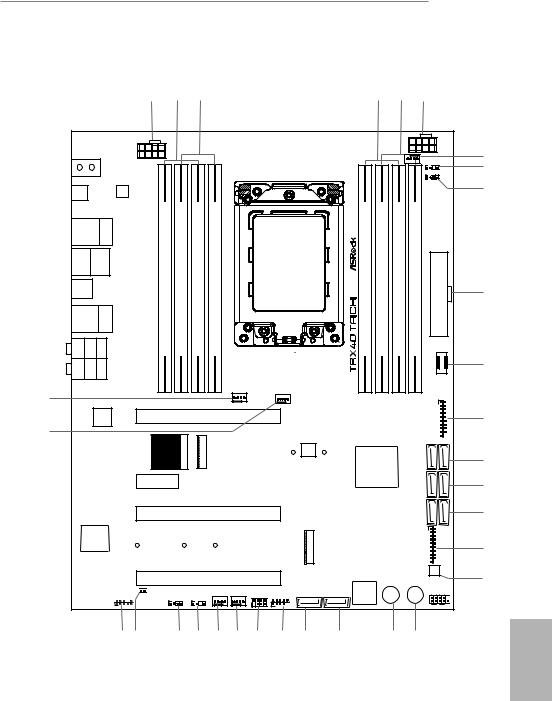
1.3 Motherboard Layout
1 |
2 |
3 |
4 |
5 |
6 |
|
ATX12V2 |
|
CPU_FAN1 |
ATX12V1 |
ADDR_LED1 |
|
1 |
|
RGB_LED1 |
|
1 |
BIOS |
|
|
|
|
LAN |
|
|
|
|
|
|
|
|
_FB1 |
|
|
|
|
|
|
|
|
|
|
|
|
|
USB 3.2 Gen1 |
Top: |
|
|
|
|
|
|
|
|
|
|||
T: USB1 |
|
|
RJ-45 |
|
|
|
|
|
|
|
|
|
|
B: USB2 |
|
(I211AT) |
module) |
module) |
module) |
module) |
module) |
module) |
module) |
module) |
|
||
USB: USBT: US3 4 3 .BGen12 |
|
/Mouse |
Keyboard PS2 |
ATXPWR1 |
|||||||||
USB 3.2 Gen2x2 |
|
|
bit,(64D2DDR4288pin- |
bit,(64D1DDR4288pin- |
bit,(64C2DDR4288pin- |
bit,(64C1DDR4288pin- |
bit,(64A1DDR4288pin- |
bit,(64A2DDR4288pin- |
bit,(64B1DDR4288pin- |
bit,(64B2DDR4288pin- |
|||
USB32_TC1 |
|
|
|
|
|
|
|
|
|
|
|
|
|
USB 3.2 Gen2 Top: |
|
|
|
|
|
|
|
|
|
||||
T: USB1 |
|
|
2.5GLAN |
|
|
|
|
|
|
|
|
|
|
|
|
(Dragon |
|
|
|
|
|
|
|
|
|
||
B: USB2 |
|
RTL8125AG) |
|
|
|
|
|
|
|
|
|
||
SPDIF Optical Bottom: |
REARSPK |
Center: |
Central/Bass |
Top: |
|
|
|
|
|
|
|
|
F_USB31_TC_1 |
MI Bottom: CIN |
FRONT |
Center: |
LINEIN |
Top: |
|
|
|
|
|
|
|
|
|
|
|
|
|
|
|
|
|
|
CHA_FAN3 |
|
|
|
|
|
|
|
|
|
|
|
|
|
/WP |
|
|
|
|
32 |
|
|
|
|
|
|
|
|
|
|
|
|
1 |
|
|
|
|
|
|
|
|
|
|
|
|
|
|
|
|
|
|
|
|
|
|
|
CPU_FAN2/WP |
|
|
|
|
|
|
LAN |
|
|
PCIE1 |
|
|
|
|
7 8 |
|||
31 |
|
|
|
|
|
|
|
|
|
|
|
|
USB3_ |
|
|
|
|
|
|
1 |
|
M21 |
|
AMD |
|
|
87SATA3 |
|
|
|
|
|
WiFi-802.11ax |
WIFIM2 |
|
BIOS |
|
|
|||
|
|
|
|
|
|
|
|
ROM |
|
|
|
|
|
|
|
|
|
|
Module |
|
|
|
|
|
|
|
|
|
|
|
|
|
|
|
|
|
TRX40 |
|
|
|
|
|
|
|
|
|
PCIE2 |
|
|
|
|
|
|
|
5 6 |
|
|
|
|
|
|
|
|
|
|
|
|
SATA3 |
|
|
|
|
|
|
|
|
|
|
|
|
|
|
|
7
8
9
10
11
12
13
14
Purity
SoundTM 4
CLRMOS1
1 


HD_AUDIO1
1
PCIE3 |
|
|
|
|
|
3 4 |
|
|
|
|
|
SATA3 |
|
|
|
|
|
|
|
|
|
|
|
|
|
|
1 |
|
|
|
M2 2 |
|
|
USB3 5 6 |
|
|
|
|
|
|
CLRC |
|
|
|
|
|
|
BTN1 |
PCIE4 |
|
|
|
|
|
|
CHA_FAN2 |
CHA_FAN1 |
|
|
Dr. |
|
PLED PWRBTN |
/WP |
/WP |
|
SATA3_1 |
SATA3_2 Debug Reset |
Power |
|
|
|
SPK_PLED1 USB_1_2 |
|
RGB_LED2 |
ADDR_LED2 |
|
|
|
|
1 |
|
1 |
|
|
1 |
HDLED |
RESET |
|
|
1 |
|
|
PANEL1
15
16
17
 18
18
30 |
29 |
28 |
27 |
26 |
25 |
24 |
23 |
22 |
21 |
20 |
19 |
English
7

|
No. |
Description |
|
|
1 |
8 pin 12V Power Connector (ATX12V1) |
|
|
2 |
2 x 288-pin DDR4 DIMM Slots (DDR4_D2, DDR4_C2) |
|
|
3 |
2 x 288-pin DDR4 DIMM Slots (DDR4_D1 DDR4_C1) |
|
|
4 |
2 x 288-pin DDR4 DIMM Slots (DDR4_A1, DDR4_B1) |
|
|
5 |
2 x 288-pin DDR4 DIMM Slots (DDR4_A2, DDR4_B2) |
|
|
6 |
8 pin 12V Power Connector (ATX12V2) |
|
|
7 |
CPU Fan Connector (CPU_FAN1) |
|
|
8 |
Addressable LED Header (ADDR_LED1) |
|
|
9 |
RGB LED Header (RGB_LED1) |
|
|
10 |
ATX Power Connector (ATXPWR1) |
|
|
11 |
Front Panel Type C USB 3.2 Gen2 Header (F_USB31_TC_1) |
|
|
12 |
USB 3.2 Gen1 Header (USB3_7_8) |
|
|
13 |
SATA3 Connectors (SATA3_7_8) |
|
|
14 |
SATA3 Connectors (SATA3_5_6) |
|
|
15 |
SATA3 Connectors (SATA3_3_4) |
|
|
16 |
USB 3.2 Gen1 Header (USB3_5_6) |
|
|
17 |
Clear CMOS Button (CLRCBTN1) |
|
|
18 |
System Panel Header (PANEL1) |
|
|
19 |
Power Button (PWRBTN1) |
|
|
20 |
Reset Button (RSTBTN1) |
|
|
21 |
SATA3 Connector (SATA3_2) |
|
|
22 |
SATA3 Connector (SATA3_1) |
|
|
23 |
USB 2.0 Header (USB_1_2) |
|
|
24 |
Power LED and Speaker Header (SPK_PLED1) |
|
|
25 |
Chassis / Waterpump Fan Connector (CHA_FAN1/WP) |
|
|
26 |
Chassis / Waterpump Fan Connector (CHA_FAN2/WP) |
|
|
27 |
Addressable LED Header (ADDR_LED2) |
|
|
28 |
RGB LED Header (RGB_LED2) |
|
|
29 |
Clear CMOS Jumper (CLRMOS1) |
|
|
30 |
Front Panel Audio Header (HD_AUDIO1) |
|
|
|||
English |
31 |
Chassis / Waterpump Fan Connector (CHA_FAN3/WP) |
|
32 |
CPU / Waterpump Fan Connector (CPU_FAN2/WP) |
||
|
|||
|
|
|
8
TRX40 Taichi
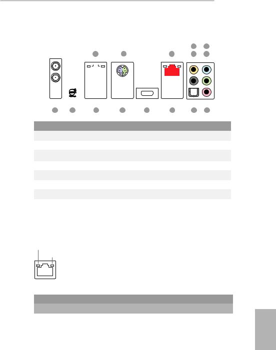
1.4 I/O Panel
|
|
|
|
|
|
|
|
|
|
|
|
|
|
|
|
|
|
|
|
|
|
|
|
|
4 |
6 |
|
|
|
|
|
1 |
|
|
|
|
|
2 |
3 |
|
|
|
|
5 |
7 |
||||||||
|
|
|
|
|
|
|
|
|
|
|
|
|
|
|
|
|
|
|
|
|
|
|
|
|
|
|
|
|
|
|
|
|
|
|
|
|
|
|
|
|
|
|
|
|
|
|
|
|
|
|
|
|
|
|
|
|
|
|
|
|
|
|
|
|
|
|
|
|
|
|
|
|
|
|
|
|
|
|
|
|
|
|
|
|
|
|
|
|
|
|
|
|
|
|
|
|
|
|
|
|
|
|
|
|
|
|
|
|
|
|
|
|
|
|
|
|
|
|
|
|
|
|
|
|
|
|
|
|
|
|
|
|
|
|
|
|
|
|
|
|
|
|
|
|
|
|
|
|
|
|
|
|
|
|
|
|
|
|
|
|
|
|
|
|
|
|
|
|
|
|
|
|
|
|
|
|
|
|
|
|
|
|
|
|
|
|
|
|
|
|
|
|
|
|
|
|
|
|
|
|
|
|
|
|
|
|
|
|
|
|
|
|
|
|
|
|
|
|
|
|
|
|
|
|
|
|
|
|
|
|
|
|
|
|
|
|
|
|
|
|
|
|
|
|
|
|
|
|
|
|
|
|
|
|
|
|
|
|
|
|
|
|
|
|
|
|
|
|
|
|
|
|
|
|
|
|
|
|
|
|
|
|
|
|
|
|
|
|
|
|
|
|
|
|
|
|
|
|
|
|
|
|
|
|
|
|
|
|
|
|
|
|
|
|
|
|
|
|
|
|
|
|
|
|
|
|
|
|
|
|
|
|
|
|
|
|
|
|
|
|
|
|
|
|
|
|
|
|
|
|
|
|
|
|
|
|
|
|
|
|
|
|
|
|
|
|
|
|
|
|
|
|
|
|
|
|
|
|
|
|
|
|
|
|
|
|
|
|
|
|
|
|
|
|
|
|
|
|
|
|
|
|
|
|
|
15 |
14 |
13 |
12 |
|
11 |
10 |
9 |
8 |
No. |
Description |
|
|
No. |
Description |
|
|
||
|
|
|
|
||||||
1 |
LAN RJ-45 Port (Intel® I211AT)* |
8 |
Microphone (Pink) |
|
|
||||
2 |
PS/2 Mouse/Keyboard Port |
|
9 |
Optical SPDIF Out Port |
|
||||
3 |
2.5G LAN RJ-45 Port |
|
10 |
USB 3.2 Gen2 Ports (USB31_1_2) |
|||||
|
(Dragon RTL8125AG)** |
|
11 |
USB 3.2 Gen2x2 Type-C Port |
|||||
4 |
Central (Orange) |
|
|
12 |
USB 3.2 Gen1 Ports (USB3_3_4) |
||||
5 |
Rear Speaker (Black) |
|
13 |
USB 3.2 Gen1 Ports (USB3_1_2)**** |
|||||
6 |
Line In (Light Blue) |
|
|
14 |
BIOS Flashback Button |
|
|||
7 |
Front Speaker (Lime)*** |
|
15 |
Antenna Ports (on I/O Panel Shield) |
|||||
|
|
|
|
|
|
|
|
|
|
* There are two LEDs on each LAN port. Please refer to the table below for the LAN port LED indications.
ACT/LINK LED
SPEED LED
LAN Port
Activity / Link LED |
Speed LED |
|
|
Status |
Description |
Status |
Description |
Off |
No Link |
Orange |
10Mbps connection |
Blinking |
Data Activity |
Orange |
100Mbps connection |
On |
Link |
Green |
1Gbps connection |
|
|
|
|
English
9
** There are two LEDs on each LAN port. Please refer to the table below for the LAN port LED indications.
ACT/LINK LED
|
|
SPEED LED |
|
|
|
|
|
|
|||
|
|
|
|
|
|
|
|
|
|
|
|
|
|
|
|
|
|
|
|
|
|
|
|
|
|
|
|
|
|
|
|
|
|
|
|
|
|
|
|
|
|
|
|
|
|||
|
LAN Port |
|
|
|
|
|
|
||||
Activity / Link LED |
|
Speed LED |
|
|
|||||||
Status |
|
Description |
|
Status |
|
Description |
|||||
Off |
|
No Link |
|
Off |
|
10Mbps connection |
|||||
|
|
|
|||||||||
Blinking |
|
Data Activity |
|
Orange |
|
100Mbps/1Gbps connection |
|||||
On |
|
Link |
|
Green |
|
2.5Gbps connection |
|||||
*** If you use a 2-channel speaker, please connect the speaker’s plug into “Front Speaker Jack”. See the table below for connection details in accordance with the type of speaker you use.
Audio Output |
Front Speaker |
Rear Speaker |
Central |
Line In |
Channels |
(No. 7) |
(No. 5) |
(No. 4) |
(No. 6) |
2 |
V |
-- |
-- |
-- |
4 |
V |
V |
-- |
-- |
6 |
V |
V |
V |
-- |
8 |
V |
V |
V |
V |
**** ACPI wake-up function is not supported on USB3_1_2 ports.
English
10

TRX40 Taichi
1.5 WiFi-802.11ax Module and ASRock WiFi 2.4/5 GHz
Antenna
WiFi-802.11ax + BT Module
This motherboard comes with an exclusive WiFi 802.11 a/b/g/n/ax + BT v5.0 module that offers support for WiFi 802.11 a/b/g/n/ax connectivity standards and Bluetooth v5.0. WiFi + BT module is an easy-to-use wireless local area network (WLAN) adapter to support WiFi + BT. Bluetooth v5.0 standard features Smart Ready technology that adds a whole new class of functionality into the mobile devices. BT 5.0 also includes Low Energy Technology and ensures extraordinary low power consumption for PCs. The 2T2R WiFi solution sets a WiFi high speed standard and offers max link rate up to 2.4Gbps.
* The transmission speed may vary according to the environment.
ASRock WiFi 2.4/5 GHz Antenna
English
11
English
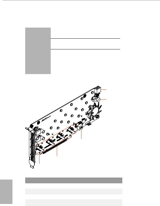
1.6 ASRock HYPER QUAD M.2 CARD
Specifications
Dimensions
Interface
Connector
•9.6-in x 4.4-in
•PCI Express 4.0 x 16 interface
•4 x Hyper M.2 Sockets, support M Key type 2242/2260/2280/22110 M.2 PCI Express module up to Gen4x4 (64 Gb/s)
•1 x Graphics 12V Power Connector
Card Layout
5
4
|
.2 card |
|
|
M |
|
|
QUAD |
|
HYPER |
ON |
3 4 |
|
1 2 |
|
|
|
3
2
1
No. Description
1Hyper M.2 Sockets
2PCI Express 4.0 x 16 Interface
3ASRock Utility Control Switch
4Card Fan Switch
5Graphics 12V Power Connector
12
TRX40 Taichi
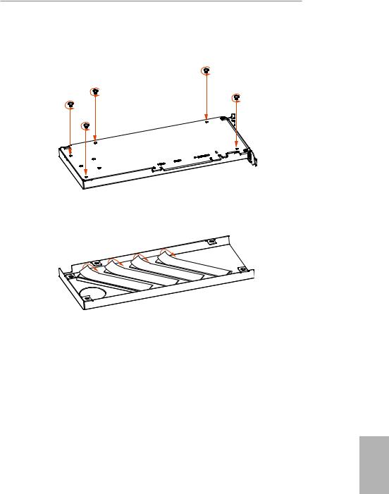
Installation Procedure
1. Remove the five screws holding the bracket in place.
2.Peel off the protective film(s) on the bracket's thermal pad(s) before you install M.2 SSD module(s).
3.Fasten the five screws holding the bracket in place.
Power off the PC and unplug the power cord. Detach all other cables from the PC.
4.Remove the PC cover.
5.Align and insert the card into a PCI Express 3.0 x16 slot on the motherboard. Press firmly until the card is securely seated in place.
English
13
English
ASRock Utility Control Switch
SW1 |
|
Utility control |
|||
On |
|
Disabled |
|||
|
|||||
Off |
|
|
Enabled |
|
|
SW2 |
|
SW3 |
|
CARD number |
|
Off |
|
Off |
|
CARD 1 |
|
|
|
||||
On |
|
Off |
|
CARD 2 |
|
Off |
|
On |
|
CARD 3 |
|
On |
|
On |
|
CARD 4 |
|
SW4: no function
Card Fan Switch
Use this switch to control the card fan speed. Off: Full (The fan runs at full speed)
ON: Half (The fan runs at half speed, with a half voltage supply)
Graphics 12V Power Connector
This card provides a 6-pin graphics 12V power connector. Install the PSU’s power cable to this connector when more than two M.2 cards* are installed.
*Intel Optane SSD 900P or other M.2 card with higher power consumption
14
TRX40 Taichi
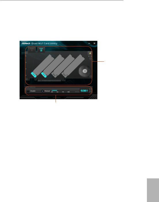
HYPER QUAD M.2 CARD Utility
With the ASRock HYPER QUAD M.2 CARD Utility, you can check that if your M.2 SSD is properly installed and adjust the fan speed. Place the Support CD into your DVD-ROM drive to run this utility or download it from the ASRock website.
M.2 SSD
Status
Select a fan speed mode
[Manual] Select a fan speed preference [Disable] Turn off the fan
English
15

Chapter 2 Installation
This is an ATX form factor motherboard. Before you install the motherboard, study the configuration of your chassis to ensure that the motherboard fits into it.
Pre-installation Precautions
Take note of the following precautions before you install motherboard components or change any motherboard settings.
•Make sure to unplug the power cord before installing or removing the motherboard. Failure to do so may cause physical injuries to you and damages to motherboard components.
•In order to avoid damage from static electricity to the motherboard’s components, NEVER place your motherboard directly on a carpet. Also remember to use a grounded wrist strap or touch a safety grounded object before you handle the components.
•Hold components by the edges and do not touch the ICs.
•Whenever you uninstall any components, place them on a grounded anti-static pad or in the bag that comes with the components.
•When placing screws to secure the motherboard to the chassis, please do not overtighten the screws! Doing so may damage the motherboard.
English
16
TRX40 Taichi
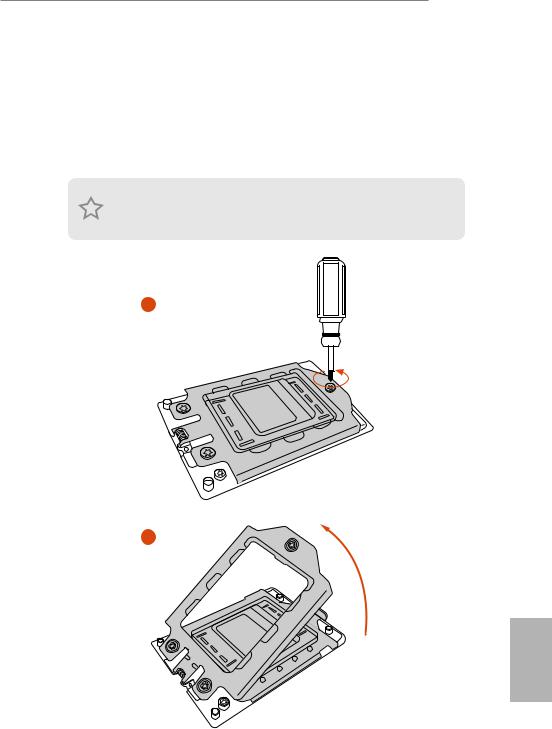
2.1 Installing the CPU
Tutorial Video
Unplug all power cables before installing the CPU.
1
2
English
17
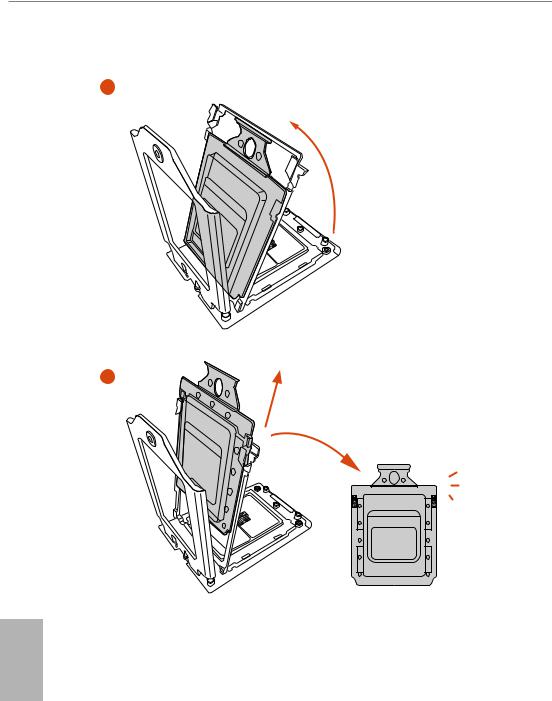
3
4
English
18
TRX40 Taichi
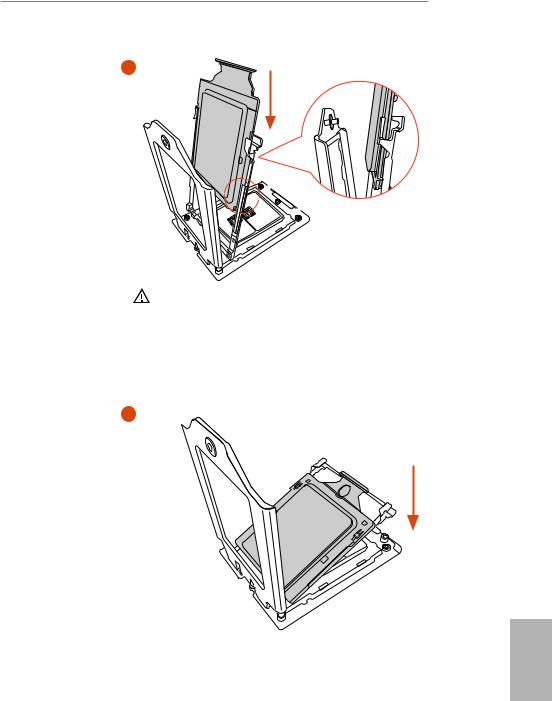
5 |
Carrier Frame with CPU |
Rail Frame
 Please make sure that the carrier frame with CPU is closely attached to the rail frame while inserting it.
Install the orange carrier frame with CPU. Don’t separate them.
6
English
19
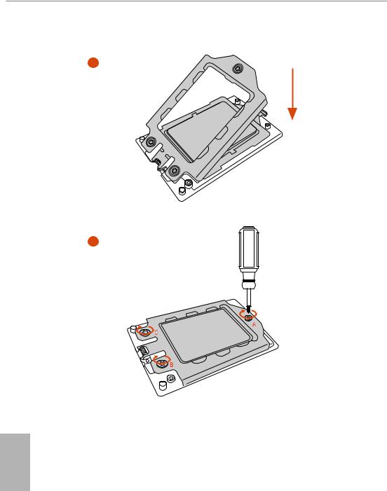
7
8
English
20
TRX40 Taichi
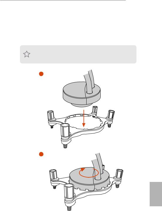
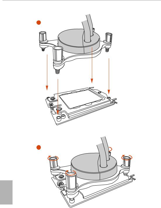
2.2 Installing the CPU Liquid Cooler
After you install the CPU into this motherboard, it is necessary to install a larger heatsink and cooling fan to dissipate heat. You also need to spray thermal grease between the CPU and the heatsink to improve heat dissipation. Make sure that the CPU and the heatsink are securely fastened and in good contact with each other.
Please turn off the power or remove the power cord before changing a CPU or heatsink.
1
2
English
21
3
4
English
22
TRX40 Taichi
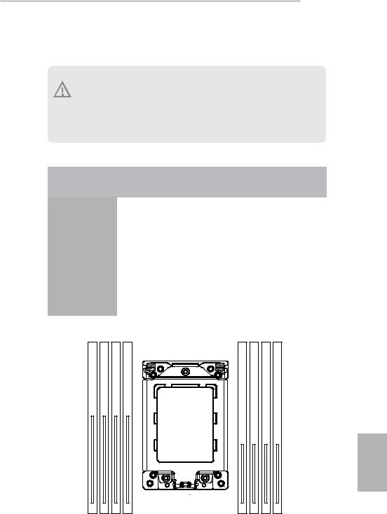
2.3 Installation of Memory Modules (DIMM)
This motherboard provides eight 288-pin DDR4 (Double Data Rate 4) DIMM slots, and supports Quad Channel Memory Technology.
1. For quad channel configuration, you always need to install identical (the same brand, speed, size and chip-type) DDR4 DIMM pairs.
2.It is not allowed to install a DDR, DDR2 or DDR3 memory module into a DDR4 slot; otherwise, this motherboard and DIMM may be damaged.
3.The DIMM only fits in one correct orientation. It will cause permanent damage to the motherboard and the DIMM if you force the DIMM into the slot at incorrect orientation.
Memory Configuration
|
|
|
|
|
|
|
|
|
2 - DIMM |
4 - DIMM |
|
|
|
|
|
|
|
8 - DIMM |
|
Priority |
1 |
2 |
3 |
||||||||||||||||
DDR4_D2 |
|
Populated |
|
|
|
|
|
|
Populated |
||||||||||
|
|
|
|
|
|
|
|||||||||||||
|
|
|
|
|
|
|
|
|
|
|
|
|
|
|
|
|
|
|
|
DDR4_D1 |
|
|
|
|
|
|
|
|
Populated |
||||||||||
|
|
|
|
|
|
|
|
|
|
|
|
|
|
|
|
|
|
|
|
DDR4_C2 |
|
Populated |
|
|
|
|
|
|
Populated |
||||||||||
|
|
|
|
|
|
|
|
|
|
|
|
|
|
|
|
|
|
|
|
DDR4_C1 |
|
|
|
|
|
|
|
|
Populated |
||||||||||
|
|
|
|
|
|
|
|
|
|
|
|
|
|
|
|
|
|
|
|
DDR4_A1 |
|
|
|
|
|
|
|
|
Populated |
||||||||||
|
|
|
|
|
|
|
|
|
|
|
|
|
|
|
|
|
|
|
|
DDR4_A2 |
Populated |
Populated |
|
|
|
|
|
|
Populated |
||||||||||
|
|
|
|
|
|
|
|
|
|
|
|
|
|
|
|
|
|
|
|
DDR4_B1 |
|
|
|
|
|
|
|
|
Populated |
||||||||||
|
|
|
|
|
|
|
|
|
|
|
|
|
|
|
|
|
|
|
|
DDR4_B2 |
Populated |
Populated |
|
|
|
|
|
|
Populated |
||||||||||
D2 D1 C2 C1 |
|
|
A1 A2 B1 B2 |
||||||||||||||||
|
|
|
|
|
|
|
|
|
|
|
|
|
|
|
|
|
|
|
|
|
|
|
|
|
|
|
|
|
|
|
|
|
|
|
|
|
|
|
|
|
|
|
|
|
|
|
|
|
|
|
|
|
|
|
|
|
|
|
|
English
23
 Loading...