


T48EM1
User Manual
Version 1.0
Published April 2014 Copyright©2014 ASRock INC. All rights reserved.
1

Copyright Notice:
No part of this manual may be reproduced, transcribed, transmitted, or translated in any language, in any form or by any means, except duplication of documentation by the purchaser for backup purpose, without written consent of ASRock Inc.
Products and corporate names appearing in this manual may or may not be registered trademarks or copyrights of their respective companies, and are used only for identification or explanation and to the owners’ benefit, without intent to infringe.
Disclaimer:
Specifications and information contained in this manual are furnished for informational use only and subject to change without notice, and should not be constructed as a commitment by ASRock. ASRock assumes no responsibility for any errors or omissions that may appear in this manual.
With respect to the contents of this manual, ASRock does not provide warranty of any kind, either expressed or implied, including but not limited to the implied warranties or conditions of merchantability or fitness for a particular purpose.
In no event shall ASRock, its directors, officers, employees, or agents be liable for any indirect, special, incidental, or consequential damages (including damages for loss of profits, loss of business, loss of data, interruption of business and the like), even if ASRock has been advised of the possibility of such damages arising from any defect or error in the manual or product.
This device complies with Part 15 of the FCC Rules. Operation is subject to the following two conditions:
(1)this device may not cause harmful interference, and
(2)this device must accept any interference received, including interference that may cause undesired operation.
CALIFORNIA, USA ONLY
The Lithium battery adopted on this motherboard contains Perchlorate, a toxic substance controlled in Perchlorate Best Management Practices (BMP) regulations passed by the California Legislature. When you discard the Lithium battery in California, USA, please follow the related regulations in advance.
“Perchlorate Material-special handling may apply, see www.dtsc.ca.gov/hazardouswaste/perchlorate”
The terms HDMI™ and HDMI High-Definition Multimedia Interface, and the HDMI logo are trademarks or registered trademarks of HDMI Licensing LLC in the United States and other countries.
2

Contents
1 Introduction......................................................... |
5 |
||
1.1 |
Package Contents.......................................................... |
5 |
|
1.2 |
Specifications................................................................. |
6 |
|
1.3 |
Motherboard Layout....................................................... |
9 |
|
1.4 |
I/O Panel ...................................................................... |
10 |
|
2 Installation........................................................... |
12 |
||
2.1 |
Screw Holes................................................................... |
12 |
|
2.2 |
Pre-installation Precautions .......................................... |
12 |
|
2.3 |
Installation of Memory Modules (DIMM)......................... |
13 |
|
2.4 |
Expansion Slot (PCI Express Slot).................................... |
14 |
|
2.5 |
Dual Monitor Feature...................................................... |
15 |
|
2.6 |
Jumpers Setup .......................................................... |
17 |
|
2.7 |
Onboard Headers and Connectors ............................ |
18 |
|
2.8 |
Driver Installation Guide ............................................. |
21 |
|
3 UEFI SETUP UTILITY.......................................... |
22 |
||
3.1 |
Introduction..................................................................... |
22 |
|
|
3.1.1 UEFI Menu Bar..................................................... |
22 |
|
|
3.1.2 |
Navigation Keys.................................................... |
23 |
3.2 |
Main Screen................................................................... |
23 |
|
3.3 |
OC Tweaker Screen....................................................... |
24 |
|
3.4 |
Advanced Screen........................................................... |
27 |
|
|
3.4.1 |
CPU Configuration................................................ |
28 |
|
3.4.2 |
North Bridge Configuration................................... |
29 |
|
3.4.3 |
South Bridge Configuration................................... |
30 |
|
3.4.4 |
Storage Configuration........................................... |
31 |
|
3.4.5 |
Super IO Configuration......................................... |
32 |
|
3.4.6 ACPI Configuration............................................... |
33 |
|
|
3.4.7 |
USB Configuration................................................ |
35 |
3.5 |
Hardware Health Event Monitoring Screen.................... |
36 |
|
3.6 |
Boot Screen.................................................................... |
37 |
|
3.7 |
Security Screen.............................................................. |
39 |
|
3.8 |
Exit Screen..................................................................... |
40 |
|
3

4 Software Support................................................ |
41 |
4.1 |
Install Operating System................................................ |
41 |
|
4.2 |
Support CD Information.................................................. |
41 |
|
|
4.2.1 Running Support CD............................................. |
41 |
|
|
4.2.2 |
Drivers Menu........................................................ |
41 |
|
4.2.3 |
Utilities Menu........................................................ |
41 |
|
4.2.4 |
Contact Information.............................................. |
41 |
4

Chapter 1: Introduction
Thank you for purchasing ASRock T48EM1 motherboard, a reliable motherboard produced under ASRock’s consistently stringent quality control. It delivers excellent performance with robust design conforming to ASRock’s commitment to quality and endurance.
In this manual, chapter 1 and 2 contain introduction of the motherboard and step- by-step guide to the hardware installation. Chapter 3 and 4 contain the configuration guide to BIOS setup and information of the Support CD.
Because the motherboard specifications and the BIOS software might be updated, the content of this manual will be subject to change without notice. In case any modifications of this manual occur, the updated version will be available on ASRock website without further notice. You may find the latest VGA cards and CPU support lists on ASRock website as well. ASRock website http://www.asrock.com
If you require technical support related to this motherboard, please visit our website for specific information about the model you are using. www.asrock.com/support/index.asp
1.1 Package Contents
ASRock T48EM1 Motherboard (Mini-ITX Form Factor)
ASRock T48EM1 Quick Installation Guide
ASRock T48EM1 Support CD
2 x Serial ATA (SATA) Data Cables (Optional)
1 x I/O Panel Shield
5

1.2 Specifications
Platform |
- Mini-ITX Form Factor |
|
- Solid Capacitor for CPU power |
|
- High Density Glass Fabric PCB |
CPU |
- AMD Embedded G-Series APU T48E |
|
- Supports AMD’s Cool ‘n’ Quiet Technology |
|
- UMI 2.5 GT/s |
Chipset |
- AMD A50M Chipset |
Memory |
- 2 x DDR3 DIMM Slots |
|
- Supports DDR3 1333/1066/800 non-ECC, un-buffered |
|
memory |
|
- Max. capacity of system memory: 16GB (see CAUTION 1) |
Expansion Slot |
- 1 x PCI Express 2.0 x16 Slot (PCIE1 @ x4 mode) |
Graphics |
- Integrated AMD Radeon HD 6250 graphics |
|
- DX11 class iGPU, Pixel Shader 5.0 |
|
- Max. shared memory 512MB |
|
- Three graphics output options: D-Sub, DVI-D and HDMI |
|
- Supports HDMI with max. resolution up to 1920x1200 |
|
(1080P) |
|
- Supports DVI-D with max. resolution up to 1920x1200 @ |
|
75Hz |
|
- Supports D-Sub with max. resolution up to 2048x1536 @ |
|
85Hz |
|
- Supports HDCP with DVI-D and HDMI Ports |
|
- Supports Full HD 1080p Blu-ray (BD) playback with DVI-D |
|
and HDMI Ports |
|
- Supports Dolby® TrueHD and DTS-HD Master Audio through |
|
HDMI Port |
Audio |
- 7.1 CH HD Audio with Content Protection (Realtek ALC892 |
|
Audio Codec) |
|
- Premium Blu-ray Audio support |
|
- Supports Surge Protection (ASRock Full Spike Protection) |
|
|
LAN |
- PCIE x1 Gigabit LAN 10/100/1000 Mb/s |
|
- Realtek RTL8111E |
|
- Supports Wake-On-LAN |
|
- Supports Lightning/ESD Protection (ASRock Full Spike |
|
Protection) |
|
- Supports LAN Cable Detection |
|
- Supports Energy Efficient Ethernet 802.3az |
|
- Supports PXE |
6

|
|
Rear Panel I/O |
- 1 x PS/2 Keyboard/Mouse Port |
|
- 1 x D-Sub Port |
|
- 1 x DVI-D Port |
|
- 1 x HDMI Port |
|
- 1 x Optical SPDIF Out Port |
|
- 6 x USB 2.0 Ports (Supports ESD Protection (ASRock Full |
|
Spike Protection)) |
|
- 1 x eSATA3 Connector |
|
- 1 x RJ-45 LAN Port with LED (ACT/LINK LED and SPEED |
|
LED) |
|
- HD Audio Jacks: Rear Speaker / Central / Bass / Line in / |
|
Front Speaker / Microphone |
Storage |
- 4 x SATA3 6.0 Gb/s Connectors, support NCQ, AHCI and |
|
Hot Plug |
Connector |
- 1 x CIR Header |
|
- 1 x COM Port Header |
|
- 1 x CPU Fan Connector (3-pin) |
|
- 2 x Chassis Fan Connectors (1 x 4-pin, 1 x 3-pin) |
|
- 1 x 24 pin ATX Power Connector |
|
- 1 x Front Panel Audio Connector |
|
- 2 x USB 2.0 Headers (Support 4 USB 2.0 ports) (Supports |
|
ESD Protection (ASRock Full Spike Protection)) |
BIOS Feature |
- 32Mb AMI UEFI Legal BIOS with GUI support |
|
- Supports Plug and Play |
|
- ACPI 1.1 compliant wake up events |
|
- Supports jumperfree |
|
- SMBIOS 2.3.1 support |
|
- DRAM, FCH, +1V, +1.8V Voltage multi-adjustment |
Hardware |
- CPU temperature sensing |
Monitor |
- Chassis temperature sensing |
|
- CPU/Chassis Fan Tachometer |
|
- CPU/Chassis Quiet Fan (Auto adjust chassis fan speed by |
|
CPU temperature) |
|
- CPU/Chassis Fan multi-speed control |
|
- Voltage monitoring: +12V, +5V, +3.3V, CPU Vcore |
OS |
- Microsoft® Windows® 8.1 32-bit / 8.1 64-bit / 8 32-bit / 8 |
|
64-bit / 7 32-bit / 7 64-bit / XP 32-bit / XP 64-bit |
Certifications |
- FCC, CE, WHQL |
-ErP/EuP ready (ErP/EuP ready power supply is required)
*For detailed product information, please visit our website: http://www.asrock.com
7

WARNING
Please realize that there is a certain risk involved with overclocking, including adjusting the setting in the BIOS, applying Untied Overclocking Technology, or using the third-party overclocking tools. Overclocking may affect your system stability, or even cause damage to the components and devices of your system.
It should be done at your own risk and expense. We are not responsible for possible damage caused by overclocking.
CAUTION!
1.Due to the operating system limitation, the actual memory size may be less than 4GB for the reservation for system usage under Windows® 8.1 / 8 / 7 / XP. For Windows® OS with 64-bit CPU, there is no such limitation.
8

1.3 Motherboard Layout
|
|
|
|
1 |
2 |
|
|
|
|
3 4 |
|
5 |
|
|
|
|
|
|
|
|
|
|
|
|
|
T48EM1 |
|
DDR3 |
|
|
|
|
|
|
|
Keyboard/Mous |
|
|
|
|
|
CHA_FAN1 |
|
|
|
|
CMOS |
|
|
|
|
|
|
|
|
|
|
|
|
|
|
|
|
|
|||
USB 2.0 |
PS2 |
|
|
|
|
|
|
|
|
|
Battery |
|
|
|||
T: USB0 |
|
|
|
|
|
|
|
|
|
|
|
|
|
|||
B: USB1 |
|
|
|
|
|
|
|
|
|
|
|
|
|
|||
|
|
|
|
|
|
|
|
|
|
|
|
|
|
|
||
|
|
e |
|
|
|
|
|
|
|
|
|
|
|
|
|
|
|
|
|
DVICON1 |
|
|
|
|
|
CPU FAN1 |
|
module)pin |
pinmodule) |
|
|
|
6 |
|
|
|
|
|
|
|
|
|
|
CLRCMOS1 |
|
|||||
|
|
|
|
|
|
|
|
|
|
|
|
1 |
||||
|
|
|
|
|
|
|
|
|
FSB800 |
FSB800 |
|
|
|
|||
|
|
|
|
|
|
|
|
|
|
|
240- |
240- |
|
|
|
|
HDMI1 |
|
|
|
|
|
|
|
|
|
|
(64bit, |
(64bit, |
|
|
|
|
22 |
|
|
|
|
|
|
|
|
|
|
DDR3 A1 |
DDR3 A2 |
|
|
|
|
|
|
|
|
|
|
|
|
|
|
|
|
|
|
7 |
||
|
USB 2.0 |
|
|
Super |
|
|
|
|
|
|
|
|
|
|||
|
T: USB2 |
|
|
|
|
|
|
|
|
|
|
|
||||
|
|
|
IO |
|
|
|
|
|
|
|
|
|
||||
|
B: USB3 |
|
|
|
|
|
|
|
CHA_FAN2 |
PANEL 1 |
|
|||||
|
|
|
|
|
|
|
|
|
|
|
PLED PWRBTN |
|||||
21 |
|
|
|
|
|
|
|
|
|
|
|
1 |
|
8 |
||
eSATA31 |
|
|
|
|
|
|
|
|
|
6Gb/s |
|
HDLED |
RESET |
|
||
|
|
|
|
|
|
|
|
|
|
|
|
|
||||
USB 2.0 |
|
Top: |
|
|
|
|
|
|
|
|
|
|
|
4 |
|
|
T: USB4 |
|
|
|
|
|
|
|
|
|
|
|
|
|
|||
|
RJ-45 |
|
|
|
|
|
|
|
|
|
|
|
SATA3 |
9 |
||
B: USB5 |
|
LAN |
|
|
|
|
|
|
|
|
|
|||||
|
|
|
|
|
PHY |
1 |
COM1 |
|
|
|
|
|
|
|
|
|
20 |
|
|
|
|
|
|
|
|
|
|
|
|
|
|
10 |
|
|
|
|
|
|
|
|
|
|
|
|
|
|
|
|
||
SPDIF Optical Bottom: |
|
|
|
HD_AUDIO1 |
|
|
|
|
|
|
|
|
|
|
|
|
|
|
|
|
|
|
USB6_7 |
|
|
|
|
|
|
|
SATA3 3 |
|
|
|
|
|
|
|
1 |
|
|
|
|
|
|
|
|
11 |
||
|
|
|
|
|
|
|
USB8_9 |
|
|
|
|
|
|
|
|
12 |
|
|
|
|
|
|
|
|
|
32Mb |
|
|
|
|
|
|
|
|
|
|
|
|
|
1 |
|
|
|
|
|
|
SPEAKER1 |
|||
|
|
|
|
|
|
|
|
|
BIOS |
|
|
|
|
|||
|
|
|
|
AUDIO |
|
1 |
CIR1 |
|
|
|
|
|
1 |
|
13 |
|
|
REARSPKFRONT Center:Center: |
CTRBASSLINEIN Top:Top: |
CODEC |
|
|
RoHS |
|
SATA3 |
|
|
DX11SATA31SATA32 |
|
||||
MICIN Bottom: |
1 |
|
|
|
PCIE1 |
|
|
|
|
|||||||
|
|
|
19 18 |
17 |
|
|
|
16 |
|
|
15 |
14 |
|
|
|
|
1 |
CPU Fan Connector (CPU_FAN1) |
12 |
SATA3 Connector (SATA3_1) |
2 |
Chassis Fan Connector (CHA_FAN1) |
13 |
Chassis Speaker Header (SPEAKER 1) |
3 |
CPU Fan |
14 |
Chassis Fan Connector (CHA_FAN2) |
4 |
CPU Heatsink |
15 |
32Mb SPI Flash |
5 |
2 x 240-pin DDR3 DIMM Slots |
16 |
PCI Express 2.0 x16 Slot (PCIE1) |
|
(DDR3_A1, DDR3_A2) |
17 |
Consumer Infrared Module Header (CIR1) |
6 |
Clear CMOS Jumper (CLRCMOS1) |
18 |
USB 2.0 Header (USB8_9) |
7 |
ATX Power Connector (ATXPWR1) |
19 |
USB 2.0 Header (USB6_7) |
8 |
System Panel Header (PANEL1) |
20 |
Front Panel Audio Header (HD_AUDIO1) |
9 |
SATA3 Connector (SATA3_4) |
21 |
COM Port Header (COM1) |
10 |
SATA3 Connector (SATA3_2) |
22 |
AMD A50M Chipset |
11 |
SATA3 Connector (SATA3_3) |
|
|
9
1.4 I/O Panel
|
|
1 |
2 |
|
|
|
|
3 |
4 |
|
|
|
|
|
|
|
|
|
|
|
|
|
|
|
||||||
|
|
|
|
|
|
|
|
|
|
|
|
|
|
|
|
|
|
|
|
|
|
5 |
|
|
|
8 |
||||
|
|
|
|
|
|
|
|
|
|
|
|
|
|
|
|
|
|
|
|
|
|
|
|
|
||||||
|
|
|
|
|
|
|
|
|
|
|
|
|
|
|
|
|
|
|
|
|
||||||||||
|
|
|
|
|
|
|
|
|
|
|
|
|
|
|
|
|
|
|
||||||||||||
|
|
|
|
|
|
|
|
|
|
|
|
|
|
|
|
|
|
|
|
|
|
|
|
6 |
|
|
|
|
|
9 |
|
|
|
|
|
|
|
|
|
|
|
|
|
|
|
|
|
|
|
|
|
|
|
|
|
||||||
|
|
|
|
|
|
|
|
|
|
|
|
|
|
|
|
|
|
|
|
|
|
|
|
|
||||||
|
|
|
|
|
|
|
|
|
|
|
|
|
|
|
|
|
|
|
|
|
|
|
|
|
||||||
|
|
|
|
|
|
|
|
|
|
|
|
|
|
|
|
|
|
|
|
|
|
|
7 |
|
|
|
|
10 |
||
|
|
|
|
|
|
|
|
|
|
|
|
|
|
|
|
|
|
|
|
|
|
|
|
|
|
|
||||
|
|
|
|
|
|
|
|
|
|
|
|
|
|
|
|
|
|
|
|
|
|
|
|
|
|
|
|
|
|
|
15 |
|
|
|
14 |
13 |
12 |
|
|
|
11 |
|
|
|
|
|
|
|
|
|
|
|
|
||||||||
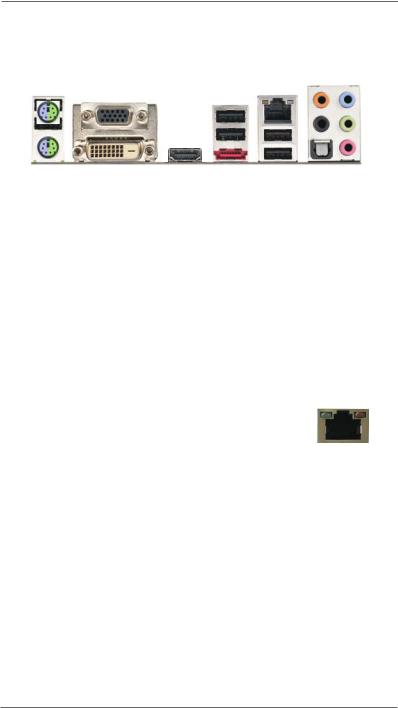
1 |
|
PS/2 Keyboard/Mouse Port (Purple/Green) |
9 |
|
Front Speaker (Lime)** |
|
|
|
|
|
|
|||||||||||||||||||
2 |
|
D-Sub Port |
|
|
|
|
10 |
|
Microphone (Pink) |
|
|
|
|
|
|
|||||||||||||||
3 |
|
USB 2.0 Ports (USB23) |
|
|
11 |
|
USB 2.0 Ports (USB45) |
|
|
|
|
|
|
|||||||||||||||||
4 |
|
LAN RJ-45 Port* |
|
|
|
|
12 |
|
eSATA3 Port |
|
|
|
|
|
|
|||||||||||||||
5 |
|
Central / Bass (Orange) |
|
|
13 |
|
HDMI Port |
|
|
|
|
|
|
|||||||||||||||||
6 |
|
Rear Speaker (Black) |
|
|
14 |
|
DVI-D Port |
|
|
|
|
|
|
|||||||||||||||||
7 |
|
Optical SPDIF Out Port |
|
|
15 |
|
USB 2.0 Ports (USB01) |
|
|
|
|
|
|
|||||||||||||||||
8Line In (Light Blue)
*There are two LED next to the LAN port. Please refer to the table below for the LAN port LED indications.
|
LAN Port LED Indications |
ACT/LINK |
SPEED |
||||||
Activity/Link LED |
|
|
SPEED LED |
||||||
|
|
LED |
LED |
||||||
Status |
Description |
|
Status |
|
Description |
|
|
|
|
Off |
No Link |
|
Off |
|
10Mbps connection |
|
|
|
|
|
|
|
|
||||||
Blinking |
Data Activity |
|
Orange |
|
100Mbps connection |
|
|
|
|
On |
Link |
|
Green |
|
1Gbps connection |
LAN Port |
|||
|
|
|
|
|
|
||||
**If you use 2-channel speaker, please connect the speaker’s plug into “Front Speaker Jack”.
See the table below for connection details in accordance with the type of speaker you use.
TABLE for Audio Output Connection
Audio Output Channels |
Front Speaker |
Rear Speaker |
Central / Bass |
Line In or |
|
(No. 9) |
(No. 6) |
(No. 5) |
Side Speaker |
|
|
|
|
(No. 8) |
|
|
|
|
|
2 |
V |
-- |
-- |
-- |
4 |
V |
V |
-- |
-- |
6 |
V |
V |
V |
-- |
|
|
|
|
|
8 |
V |
V |
V |
V |
10
To enable Multi-Streaming function, you need to connect a front panel audio cable to the front panel audio header. After restarting your computer, you will find “Mixer” tool on your system.
Please select “Mixer ToolBox”  , click “Enable playback multi-streaming”, and click
“ok”. Choose “2CH”, “4CH”, “6CH”, or “8CH” and then you are allowed to select “Realtek HDA Primary output” to use Rear Speaker, Central/Bass, and Front Speaker, or select “Realtek HDA Audio 2nd output” to use front panel audio.
11
Chapter 2: Installation
This is a Mini-ITX form factor motherboard. Before you install the motherboard, study the configuration of your chassis to ensure that the motherboard fits into it.
Make sure to unplug the power cord before installing or removing the motherboard. Failure to do so may cause physical injuries to you and damages to motherboard components.
2.1 Screw Holes
Place screws into the holes indicated by circles to secure the motherboard to the chassis.
Do not over-tighten the screws! Doing so may damage the motherboard.
2.2 Pre-installation Precautions
Take note of the following precautions before you install motherboard components or change any motherboard settings.
1.Unplug the power cord from the wall socket before touching any component.
2.To avoid damaging the motherboard components due to static electricity, NEVER place your motherboard directly on the carpet or the like. Also remember to use a grounded wrist strap or touch a safety grounded object before you handle components.
3.Hold components by the edges and do not touch the ICs.
4.Whenever you uninstall any component, place it on a grounded antistatic pad or in the bag that comes with the component.
Before you install or remove any component, ensure that the power is switched off or the power cord is detached from the power supply.
Failure to do so may cause severe damage to the motherboard, peripherals, and/or components.
12
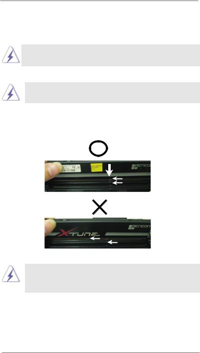
2.3 Installation of Memory Modules (DIMM)
T48EM1 motherboard provides two 240-pin DDR3 (Double Data Rate 3) DIMM slots.
It is not allowed to install a DDR or DDR2 memory module into DDR3 slot; otherwise, this motherboard and DIMM may be damaged.
Installing a DIMM
Please make sure to disconnect power supply before adding or removing DIMMs or the system components.
Step 1. Unlock a DIMM slot by pressing the retaining clips outward.
Step 2. Align a DIMM on the slot such that the notch on the DIMM matches the break on the slot.
notch break
notch
break
The DIMM only fits in one correct orientation. It will cause permanent damage to the motherboard and the DIMM if you force the DIMM into the slot at incorrect orientation.
Step 3. Firmly insert the DIMM into the slot until the retaining clips at both ends fully snap back in place and the DIMM is properly seated.
13
 Loading...