

Page 1
Service Source
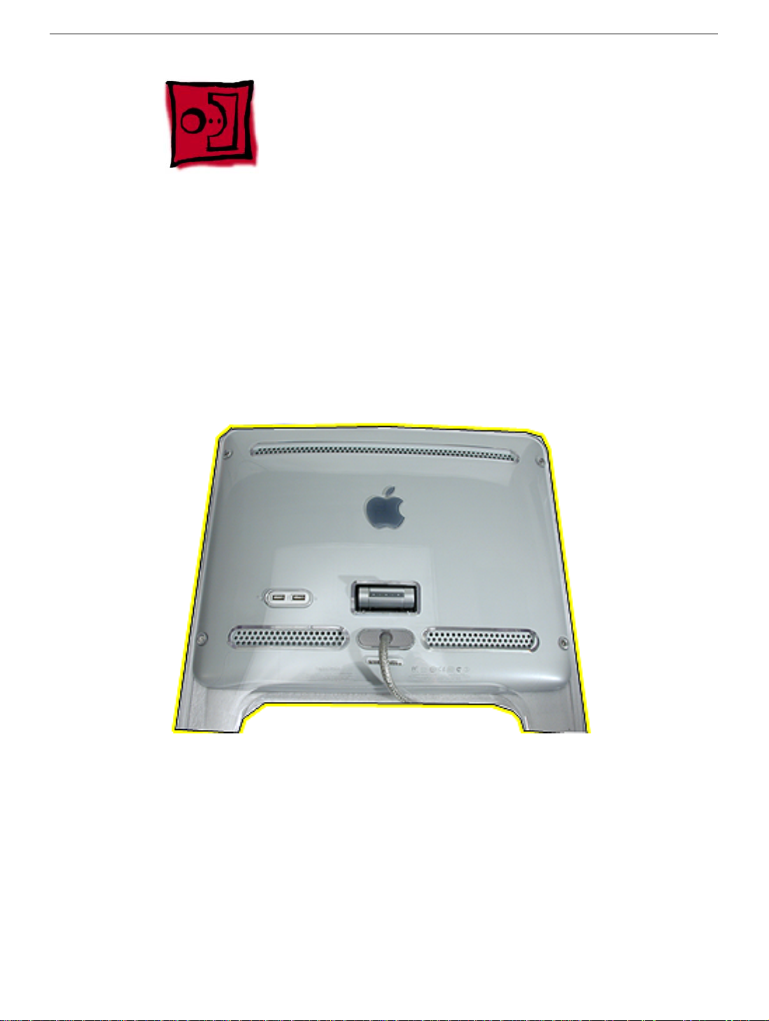
Apple Studio Display 15” LCD
(ADC)
© 2002 Apple Computer, Inc. All rights reserved.
Page 2

Apple Studio Display 15” LCD (ADC)
Apple Studio Display 15” (ADC) -
1
Page 3
Service Source
Take Apart
Studio Display 15” LCD (ADC)
© 2002 Apple Computer, Inc. All rights reserved.
Page 4

Tools
The following tools are recommended for the take apart procedures.
• 2mm hex
• phillips #2 screwdriver
• jeweler’s screwdriver set
• ESD wriststrap and mat
• white cotton gloves (922-1592)
• nylon probe tool (922-5065)
Tools
Studio Display 15” LCD (ADC) Take Apart -
1
Page 5
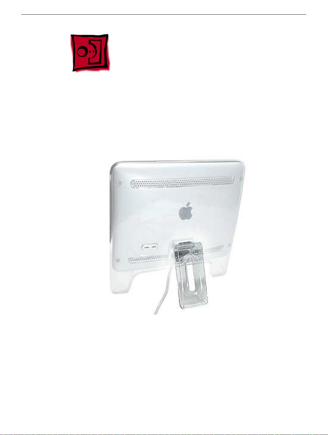
Foot Assembly
Tools
This procedure requires the following tools:
• 2mm hex driver
• White gloves for handling plastics
Part Location
Preliminary Steps
Before you begin, do the following:
• Place the computer face down on an ESD mat or soft cloth.
damaged. The white gloves prevent fingerprints.
2
Studio Display 15” (ADC) Take Apart
Note:
Plastics are easily
Foot Assembly
Page 6
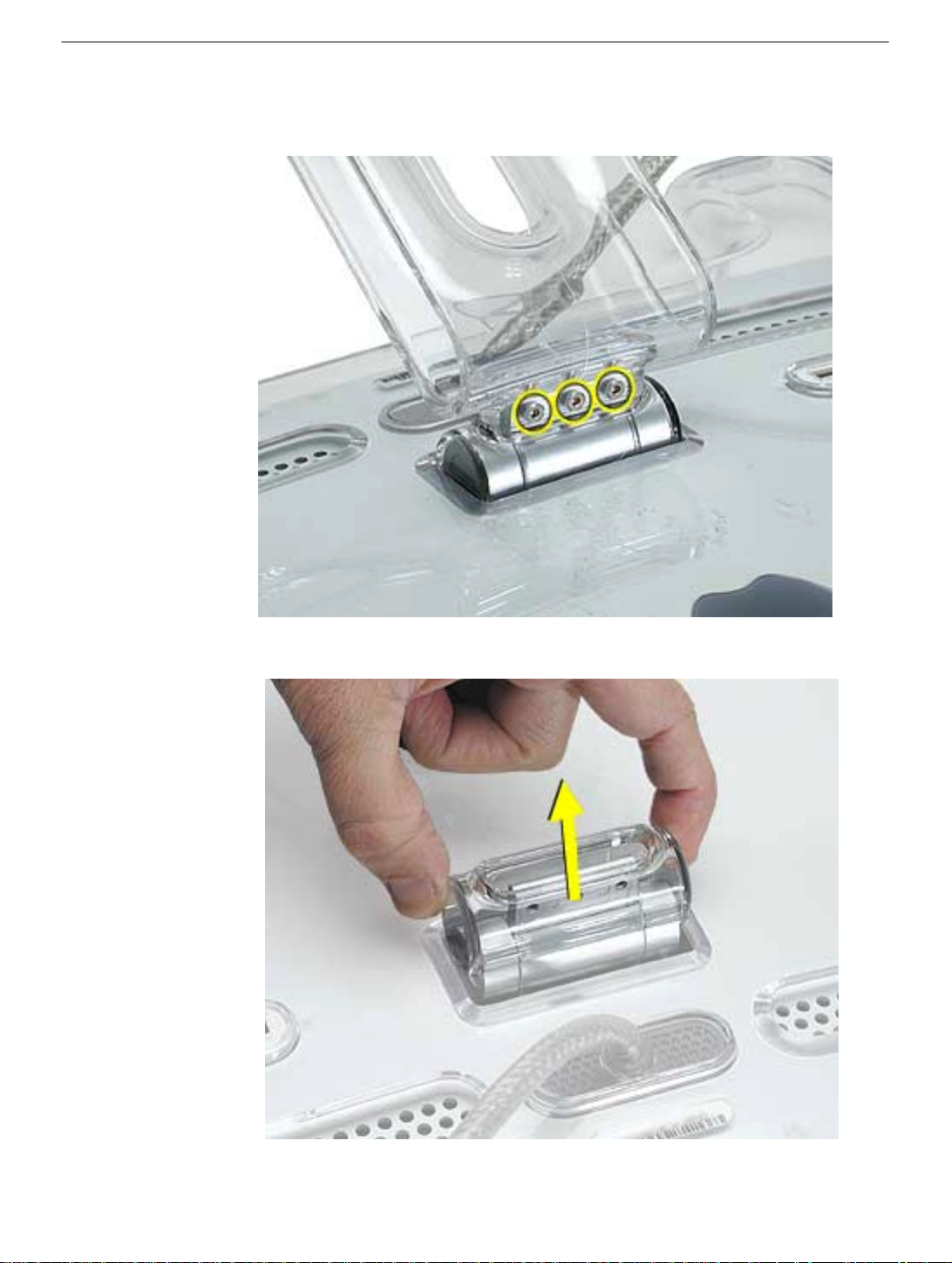
Procedure
1. Remove three screws.
2. Lift the clear hinge cap from the display.
Foot Assembly
Studio Display 15” LCD (ADC) Take Apart -
3
Page 7
Back Cover
Tools
This procedure requires the following tools:
• 2mm hex driver
• White gloves for handling plastics
Part Location
Preliminary Steps
Before you begin, do the following:
• Place the computer face down on an ESD mat
• Remove the foot assembly
4
Studio Display 15” (ADC) Take Apart
Back Cover
Page 8
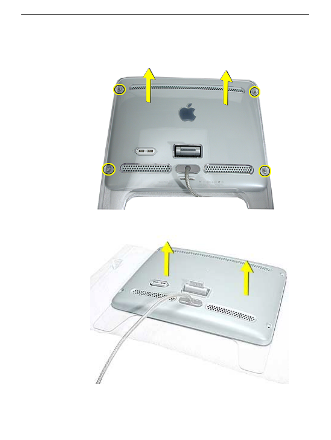
Procedure
1. Remove four T-8 screws on the back cover. Remove the back cover.
2. Lift and remove the inner back cover.
Back Cover
Studio Display 15” LCD (ADC) Take Apart -
5
Page 9
Rear Shield
Tools
• Phillips #2
Part Location
Preliminary Steps
Before you begin, do the following:
• Place the computer face down on an ESD mat
• Remove the foot assembly.
• Remove the back cover and inner rear cover.
6
Studio Display 15” (ADC) Take Apart
Rear Shield
Page 10
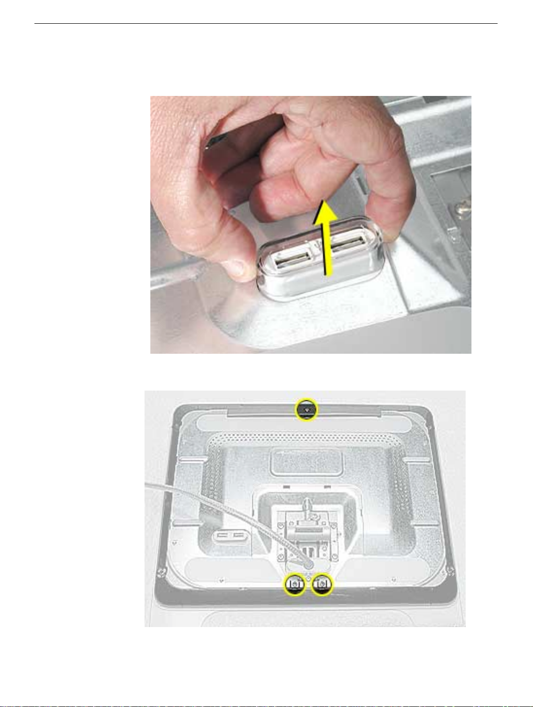
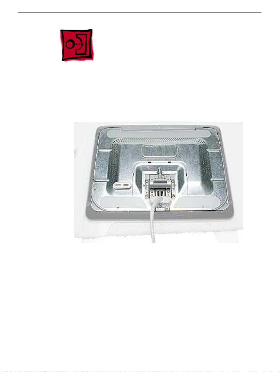
Procedure
1. Remove the plastic USB trim ring.
2. Remove three Phillips screws on the shield.
Rear Shield
Studio Display 15” LCD (ADC) Take Apart -
7
Page 11
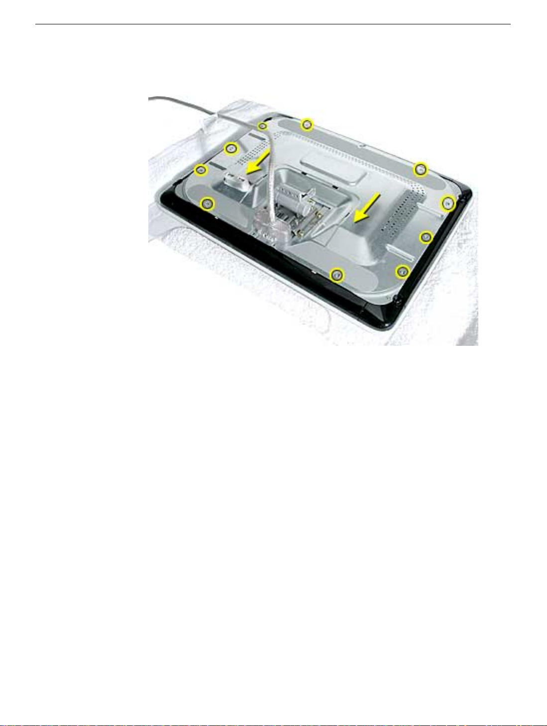
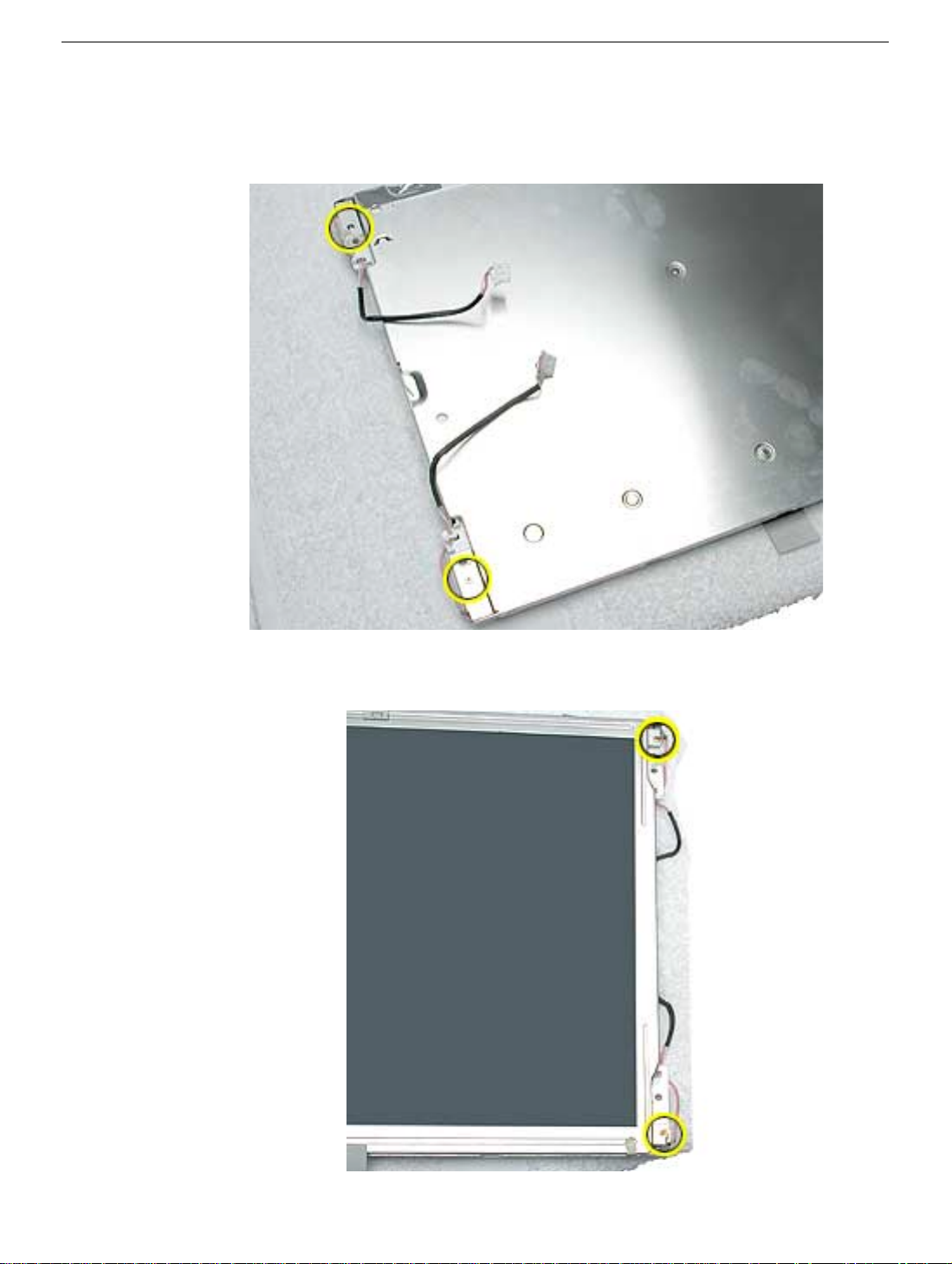
3. Slide the shield toward the ADC (Apple Display Connector), unlatching the metal tabs
(circled below).
cables don’t get pinched.
Note:
When reinstalling the metal shield, make sure that the display
4. Lift the shield off the back of the display.
8
Studio Display 15” (ADC) Take Apart
Rear Shield
Page 12
Clips, Horizontal and Vertical
Tools
• Plastic flat blade or similar tool to pry the clips off
Part Location
Preliminary Steps
Before you begin, do the following:
• Place the computer face down on an ESD mat
• Remove the foot assembly.
• Remove the back cover and inner rear cover.
• Remove the rear shield.
Clips, Horizontal and Vertical
Studio Display 15” LCD (ADC) Take Apart -
9
Page 13
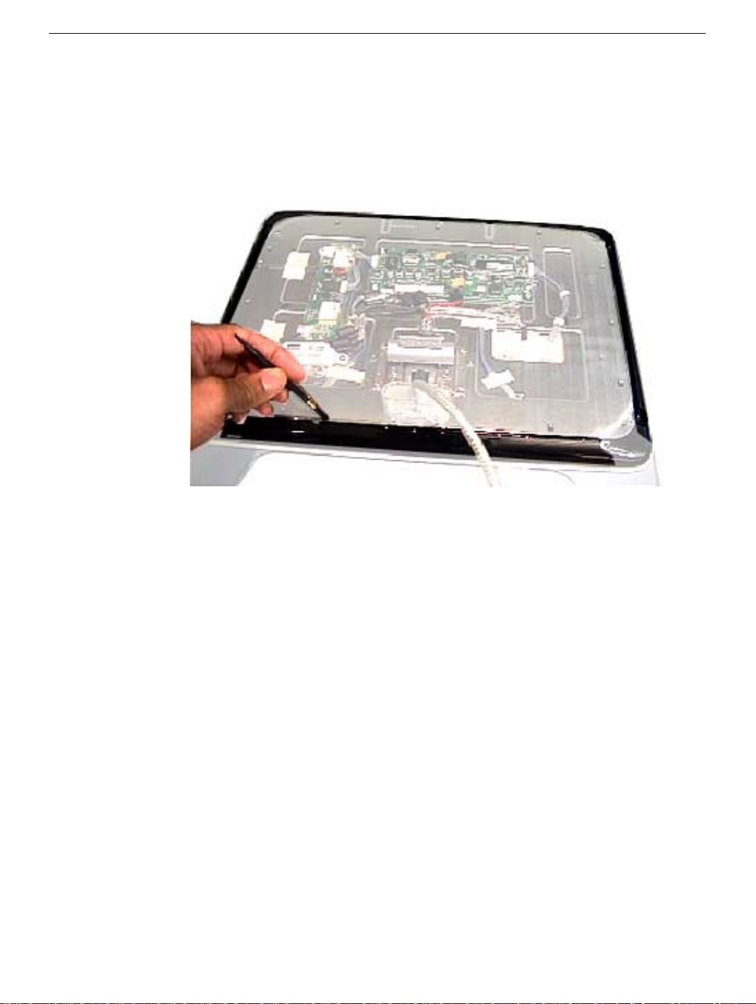
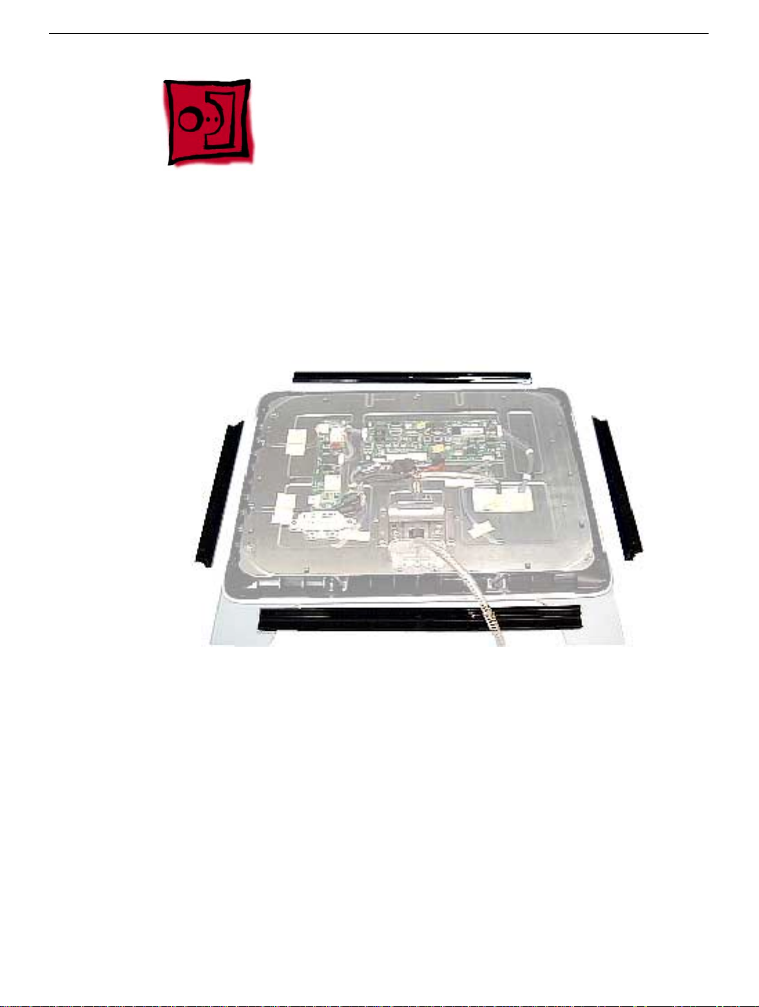
Procedure
1. With the plastic flatblade screwdriver, or nylon probe tool (922-5065) pry between the
clip and metal chassis to remove the two horizontal and two vertical clips.
10
Studio Display 15” (ADC) Take Apart
Clips, Horizontal and Vertical
Page 14
Main PCB
Tools
• Phillips #2
Part Location
Main PCB
Preliminary Steps
Before you begin, do the following:
• Place the computer face down on an ESD mat
• Remove the foot assembly.
• Remove the back cover and the inner rear cover.
• Remove the rear shield.
Studio Display 15” LCD (ADC) Take Apart -
11
Page 15
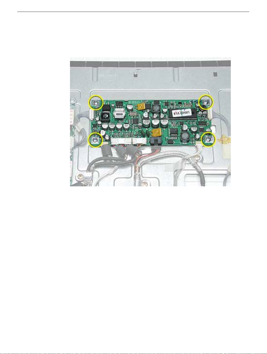
Procedure
1. Disconnect the connectors and then remove the four screws. Lift the main board from
the chassis.
12
Studio Display 15” (ADC) Take Apart
Main PCB
Page 16
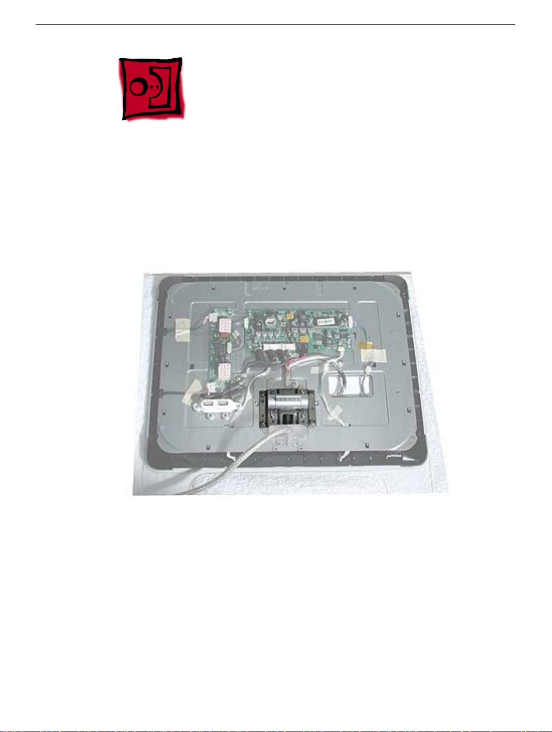
Inverter
Tools
• Phillips #2
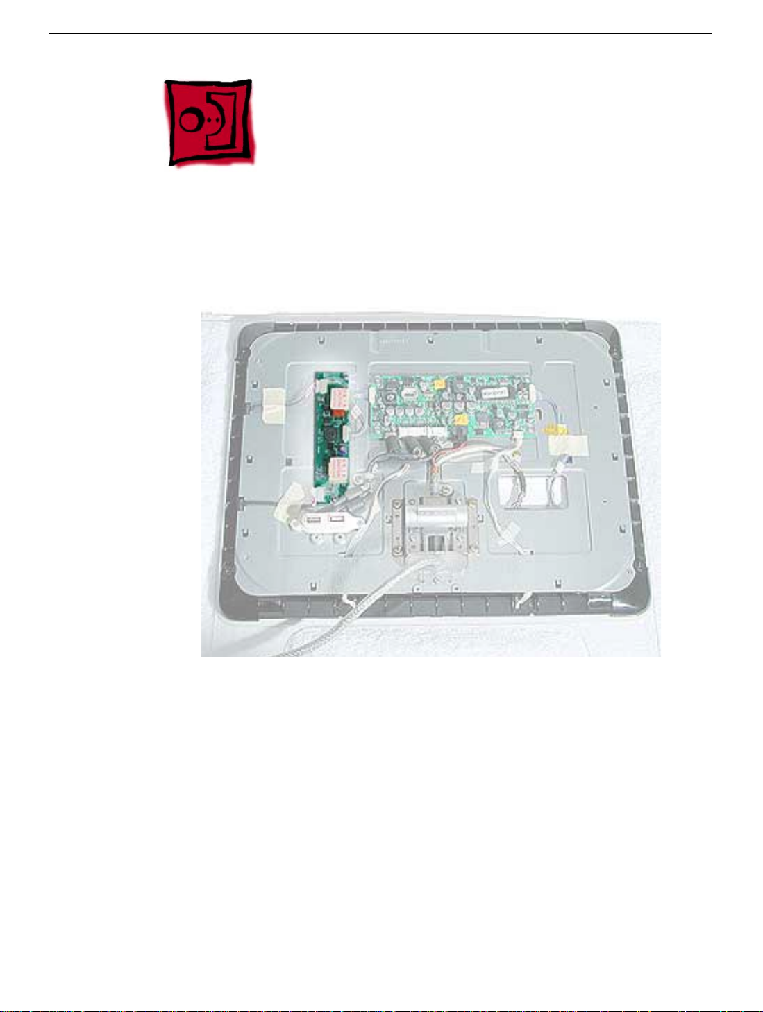
Part Location
Inverter
Preliminary Steps
Before you begin, do the following:
• Place the computer face down on an ESD mat
• Remove the foot assembly.
• Remove the back cover and the inner rear cover.
• Remove the rear shield.
Studio Display 15” LCD (ADC) Take Apart -
13
Page 17
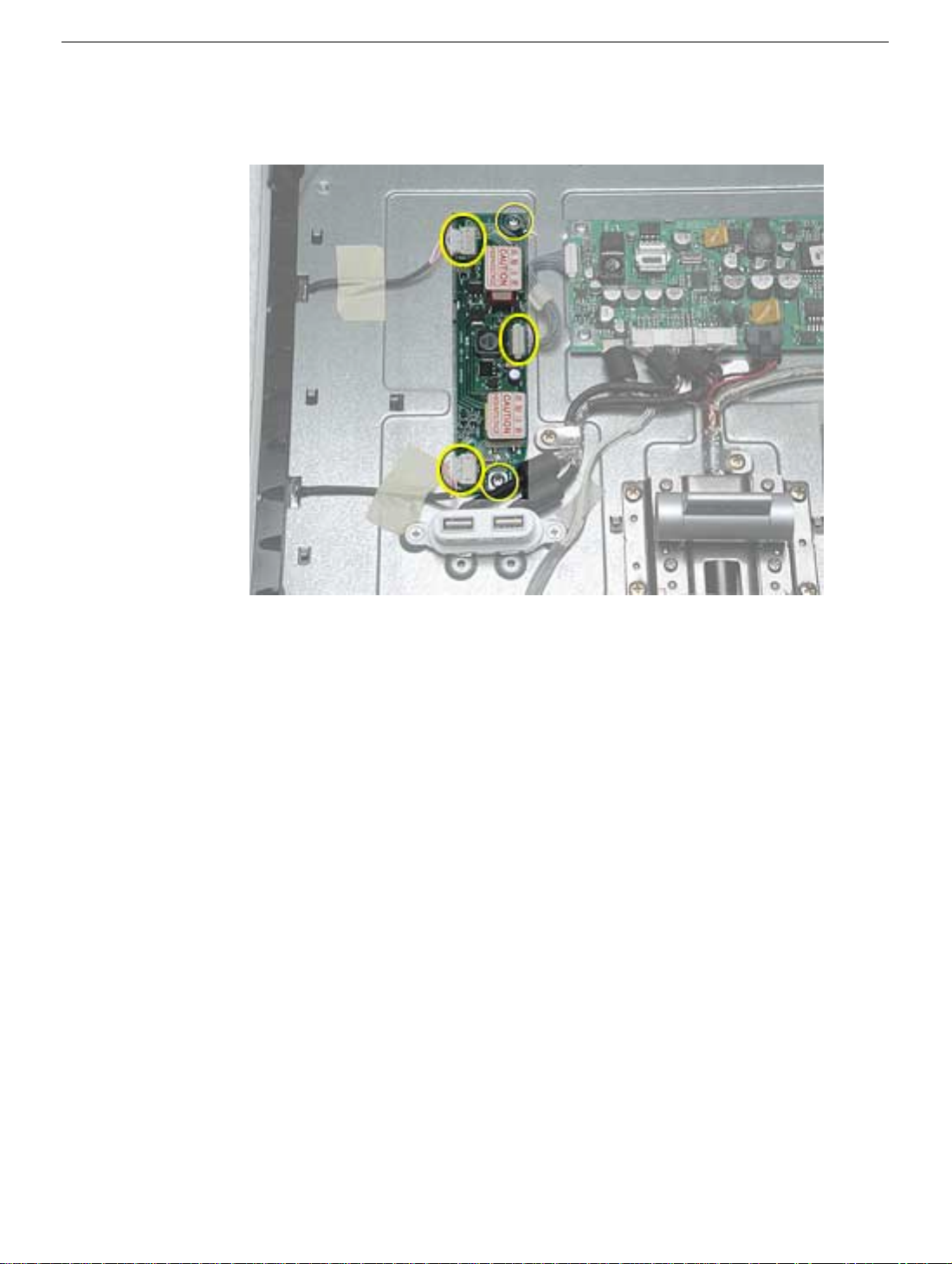
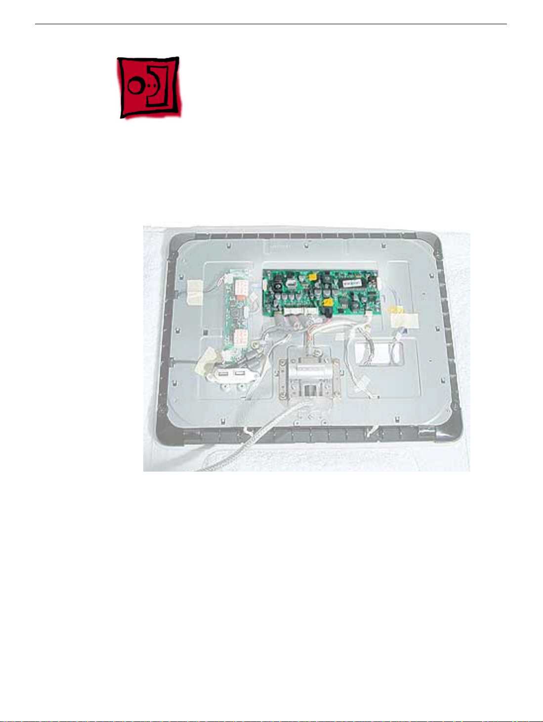
Procedure
1. Disconnect three connectors and remove two screws.
2. Lift the inverter from the chassis.
14
Studio Display 15” (ADC) Take Apart
Inverter
Page 18

USB Cable Assembly
Tools
This procedure requires the following tools:
• Phillips #2
Part Location
Preliminary Steps
Before you begin, do the following:
• Place the computer face down on an ESD mat
• Remove the foot assembly.
• Remove the back cover and the inner rear cover.
• Remove the rear shield.
USB Cable Assembly
Studio Display 15” LCD (ADC) Take Apart -
15
Page 19
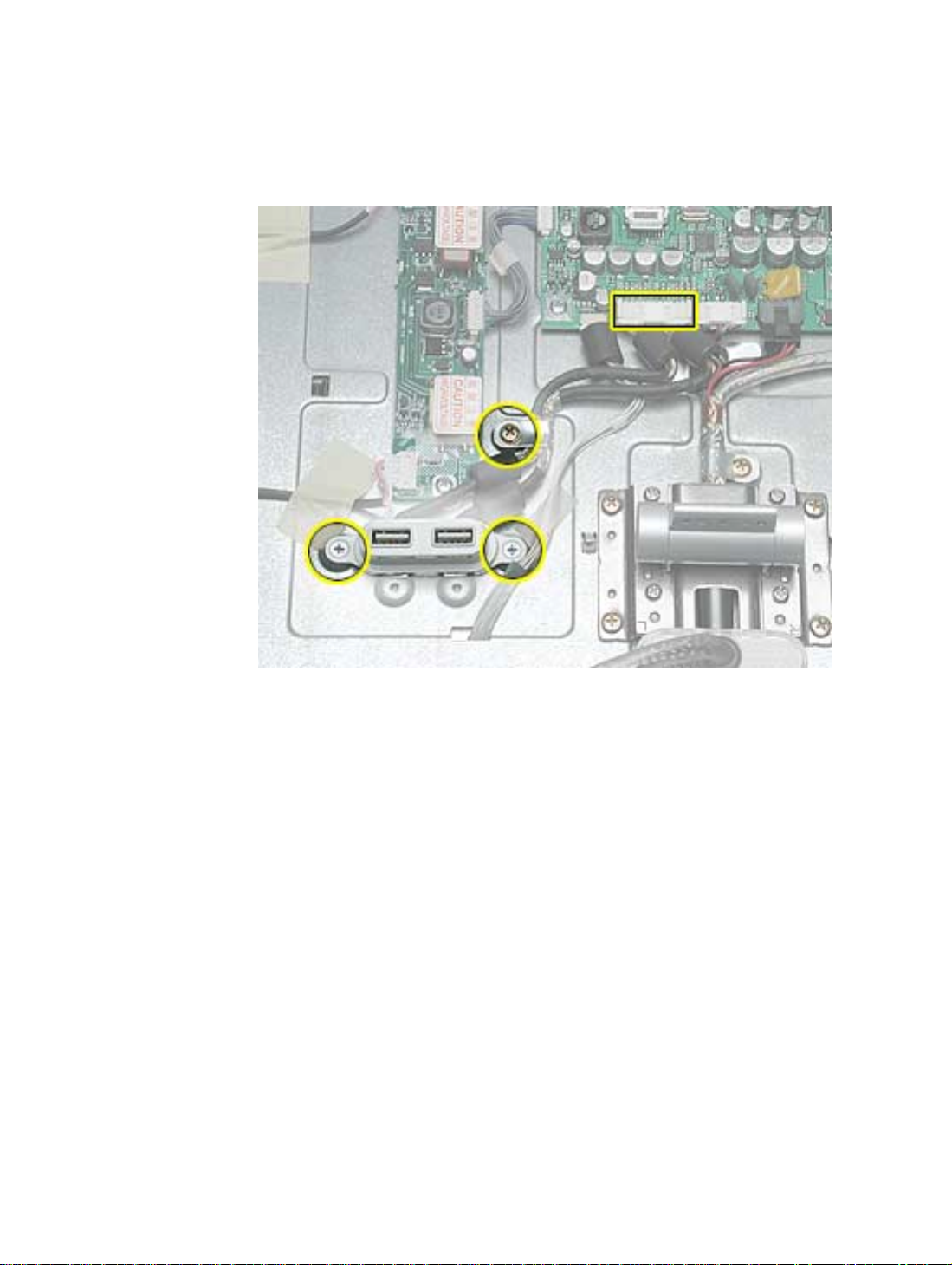
Procedure
1. Disconnect the USB connector on the main board and remove three screws. Lift the
cable connector from the chassis.
16
Studio Display 15” (ADC) Take Apart
USB Cable Assembly
Page 20
Hinge
Tools
This procedure requires the following tools:
• Phillips #2
Part Location
Hinge
Preliminary Steps
Before you begin, do the following:
• Place the computer face down on an ESD mat
• Remove the foot assembly.
• Remove the back cover and the inner rear cover.
• Remove the rear shield.
Studio Display 15” LCD (ADC) Take Apart -
17
Page 21
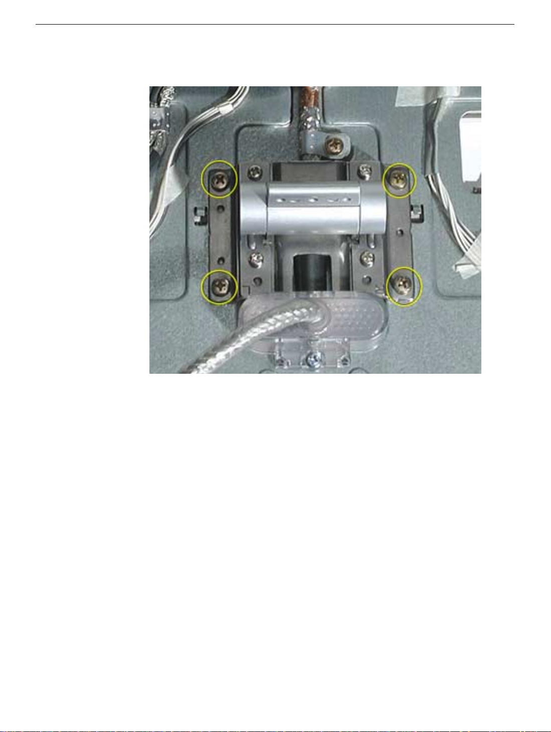
Procedure
1. Remove the four hinge screws.
2. Lift the hinge off the chassis.
18
Studio Display 15” (ADC) Take Apart
Hinge
Page 22
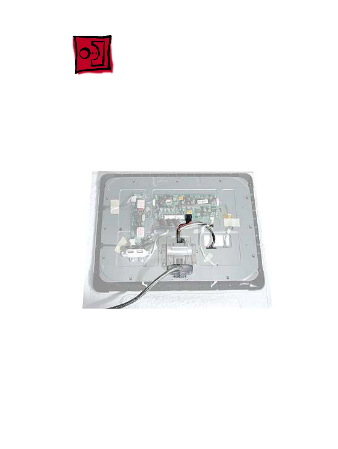
ADC Cable
Tools
This procedure requires the following tools:
• Phillips #2
Part Location
ADC Cable
Preliminary Steps
Before you begin, do the following:
• Place the computer face down on an ESD mat
• Remove the foot assembly.
• Remove the back cover and the inner rear cover.
• Remove the rear shield.
• Remove the hinge.
Studio Display 15” LCD (ADC) Take Apart -
19
Page 23
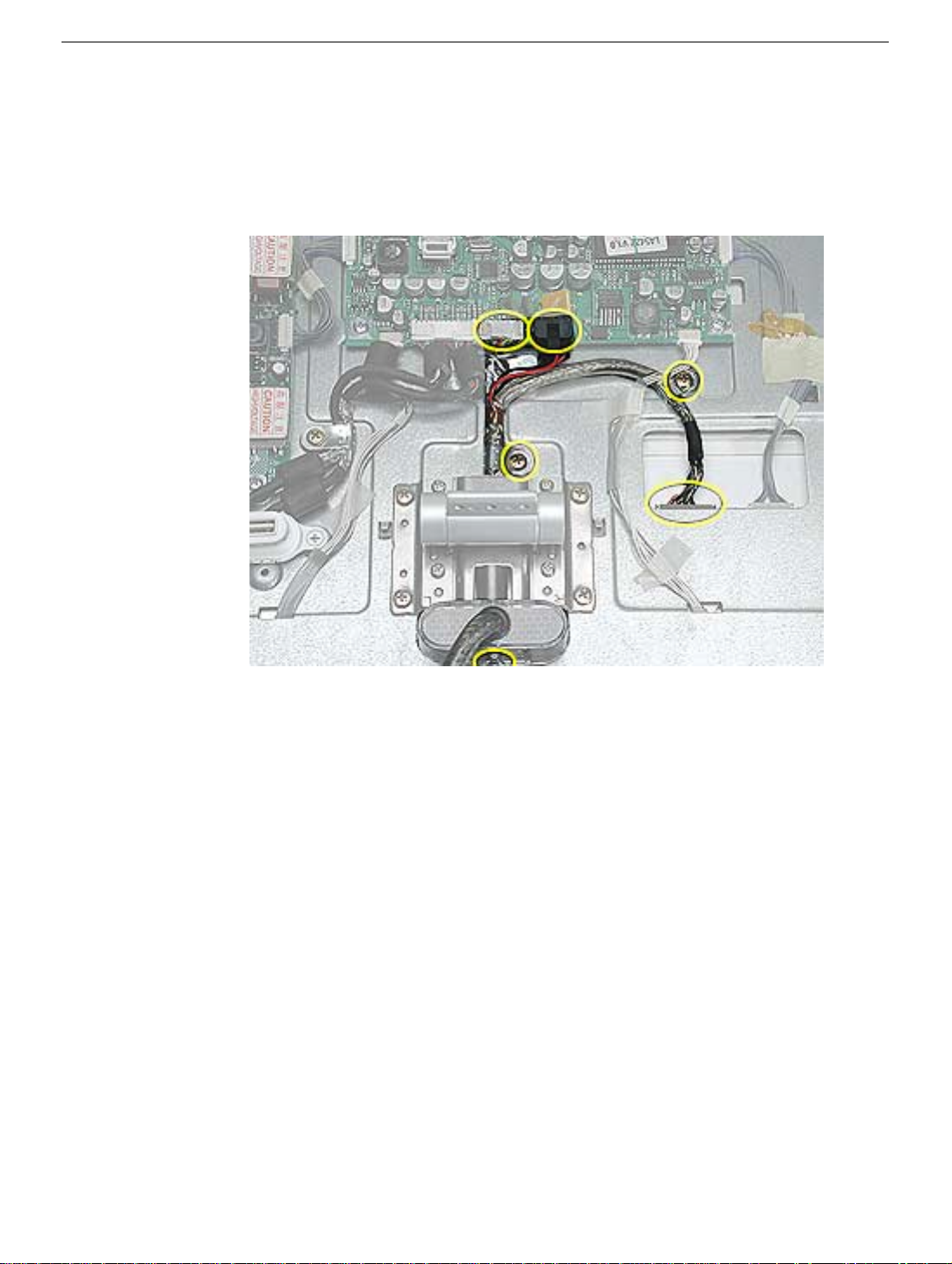
Procedure
1. Note: The hinge would already be removed.
Disconnect the three ADC cables and remove three screws (one is located toward the
bottom of the ADC cable).
2. Lift the ADC cable off the chassis.
20
Studio Display 15” (ADC) Take Apart
ADC Cable
Page 24
Front Bezel
Tools
This procedure requires the following tools:
• Phillips #2
Part Location
Front Bezel
Preliminary Steps
Before you begin, do the following:
• Place the computer face down on an ESD mat or soft cloth.
damaged. The white gloves prevent fingerprints.
• Remove the foot assembly.
• Remove the back cover and the inner rear cover.
• Remove the rear shield.
Studio Display 15” LCD (ADC) Take Apart -
Note:
Plastics are easily
21
Page 25
Procedure
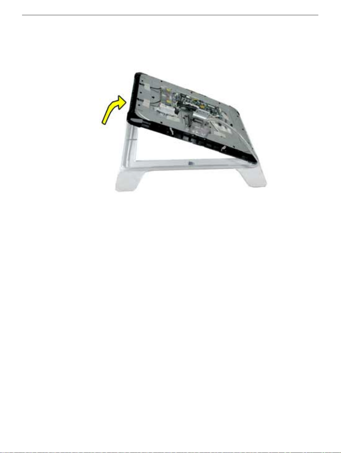
1. Lift the chassis and LCD panel off the front bezel.
22
Studio Display 15” (ADC) Take Apart
Front Bezel
Page 26

Touch Switches
Tools
This procedure requires the following tools:
• Phillips #2
Part Location
Touch Switches
Preliminary Steps
Before you begin, do the following:
• Place the computer face down on an ESD mat
• Remove the foot assembly.
• Remove the back cover and the inner rear cover.
• Remove the rear shield.
• Remove the horizontal and vertical clips
• Remove front bezel
Studio Display 15” LCD (ADC) Take Apart -
23
Page 27

Procedure
1. Remove the screw on each touch switch.
24
Studio Display 15” (ADC) Take Apart
Touch Switches
Page 28

2. Disconnect the touch switches from their cable connectors (two middle circles below).
The touch switches rest on the rubber boots (two outer circles below); set them aside
so you don’t lose them.
Touch Switches
Studio Display 15” LCD (ADC) Take Apart -
25
Page 29

LCD Display
Tools
This procedure requires the following tools:
• Phillips #2
Part Location
Preliminary Steps
Before you begin, do the following:
• Place the computer face down on an ESD mat
• Remove the foot assembly.
• Remove the back cover and the inner rear cover.
• Remove the rear shield.
• Remove the horizontal and vertical clips.
26
Studio Display 15” (ADC) Take Apart
LCD Display
Page 30

Procedure
1. Remove four LCD screws. Replacement Note: If you are replacing the LCD panel,
remove the square piece of gray tape (stuck on the panel between the touch switches)
and stick it on the replacement panel. The tape is cosmetic and goes behind the Apple
logo in the bezel.
2. Carefully turn the panel over. Disconnect the backlight bulb cables from the inverter
board and the touch switch cables from the touch switch boards.
LCD Display
Studio Display 15” LCD (ADC) Take Apart - 27
Page 31

3. Separate the metal chassis and black plastic panel cradle to access the backlight
cables. Pull the bulb cables through the openings in the plastic cradle.
4. Set the metal chassis and plastic cradle aside.
28 Studio Display 15” (ADC) Take Apart
LCD Display
Page 32
Bulbs and Bulb Shield
Tools
This procedure requires the following tools:
• Jeweler’s screwdriver
Part Location
Preliminary Steps
Before you begin, do the following:
• Place the computer face down on an ESD mat
• Remove the foot assembly.
• Remove the back cover and the inner rear cover.
• Remove the rear shield.
• Remove the horizontal and vertical clips
• Disconnect the touch switches.
• Remove the LCD panel
Bulbs and Bulb Shield
Studio Display 15” LCD (ADC) Take Apart - 29
Page 33
Procedure
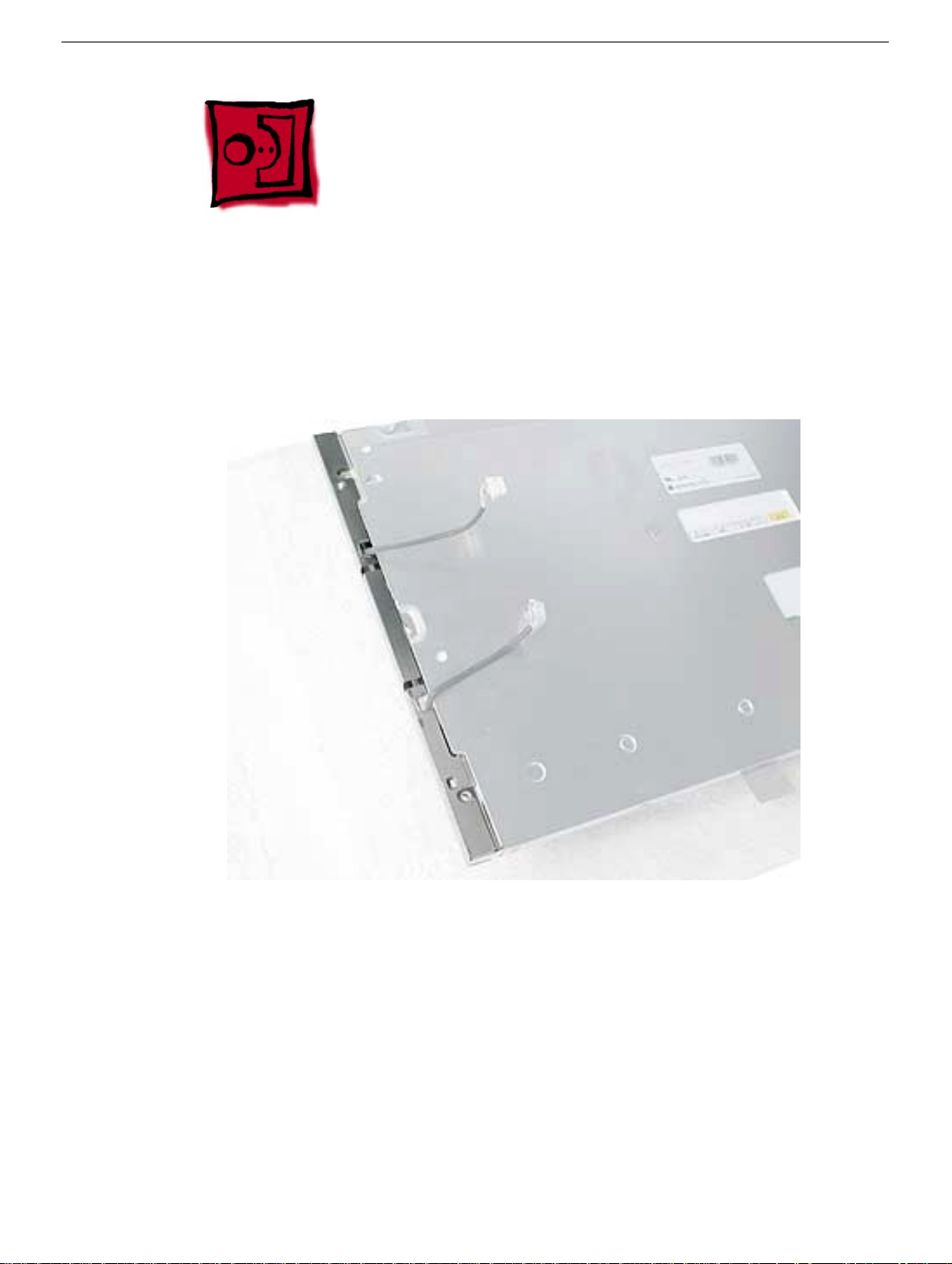
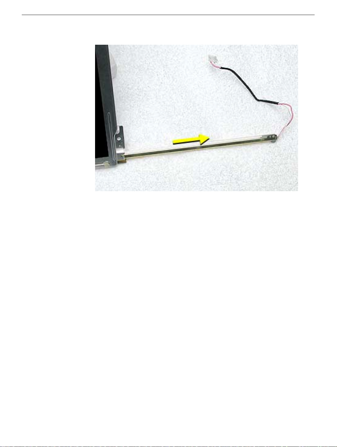
1. Carefully remove the bulb shield from the panel. There are two tabs (located near the
arrows below) that hold the shield in place. Replacement Note: When replacing the
shield be very careful not to pinch the bulb wires on the shield.
30 Studio Display 15” (ADC) Take Apart
Bulbs and Bulb Shield
Page 34
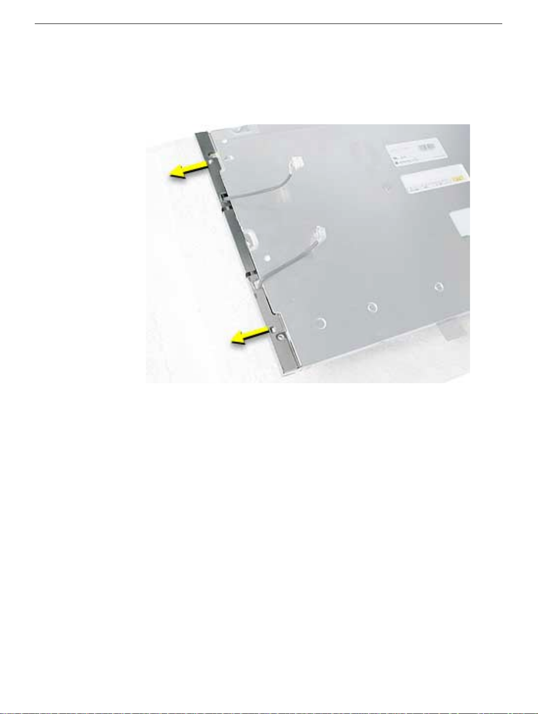
2. Note: This procedure shows removing both bulbs. Remove the screw (for each bulb)
on the back side of the panel. Carefully unhook the bulb cables that are routed
through the tab holders Important: The bulbs are very delicate and will break if
excessive force is applied to the bulb tray.
3. Turn the panel over. Remove the screw (for each bulb) on the top side of the LCD
panel. Replacement Note: Short screws go on the top side, long screws on the back.
Bulbs and Bulb Shield
Studio Display 15” LCD (ADC) Take Apart - 31
Page 35
4. Carefully remove the bulb(s) from the panel. Note: Don’t touch the bulb.
32 Studio Display 15” (ADC) Take Apart
Bulbs and Bulb Shield
Page 36

Bulbs and Bulb Shield
Studio Display 15” LCD (ADC) Take Apart - 33
Page 37
Service Source
Troubleshooting
Studio Display 15” LCD (ADC)
© 2002 Apple Computer, Inc. All rights reserved.
Page 38
General Information
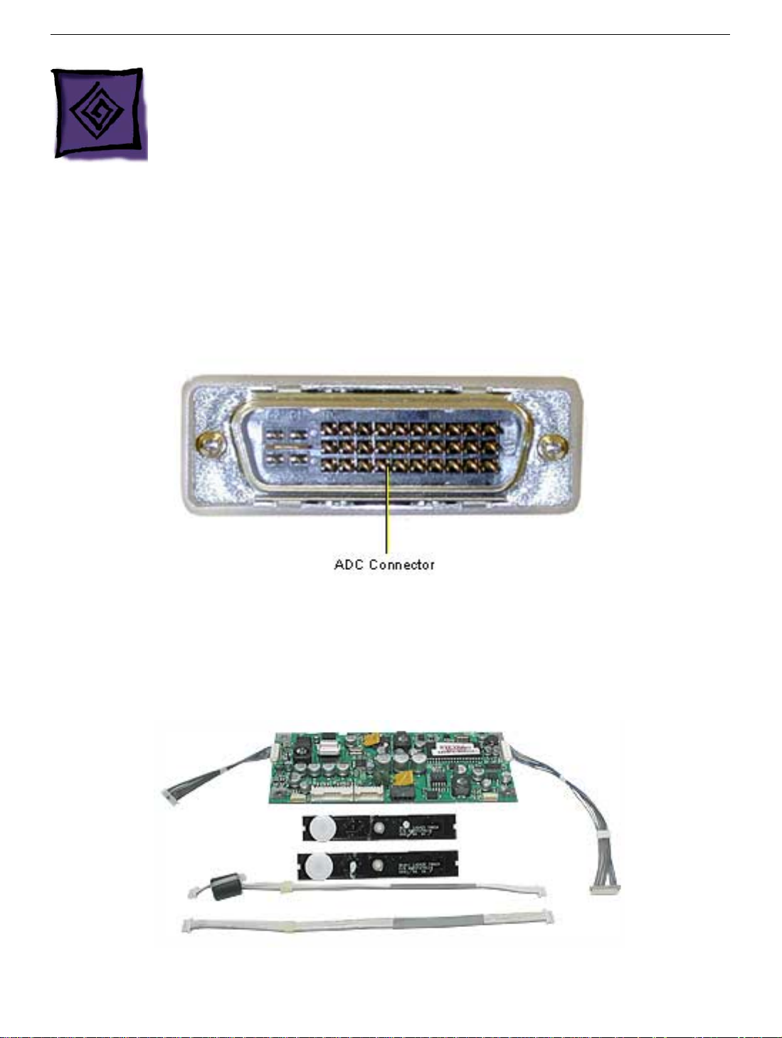
1. ADC Connector and Bent Pins: Always check for bent pins on the ADC connector and/or the video
card before replacing service parts. A damaged ADC connector on the display will ruin any video card it’s
plugged into (and vice versa). It’s important to isolate and repair damaged connectors quickly or risk
damaging every display and video card.
2. Touch switches: The touch switch kit (076-0891) shown below consists of a replacement main board,
two touch switches, and touch switch cables. The touch switch kit should only be installed when the
customer reports that the display starts up and/ or shuts down intermittently when wireless devices are
used in close proximity. The kit also provides users with the ability to disable the touch switches to
prevent false activation. The instructions for disabling the touch switches can be found in Knowledge
Base article 58813.
General Information
Studio Display 15” LCD ( ADC) - 1
Page 39
Most displays already have the touch switch kit features built in to the display so the touch
switch kit is not necessary. However,
below taken from Knowledge Base article 58813.
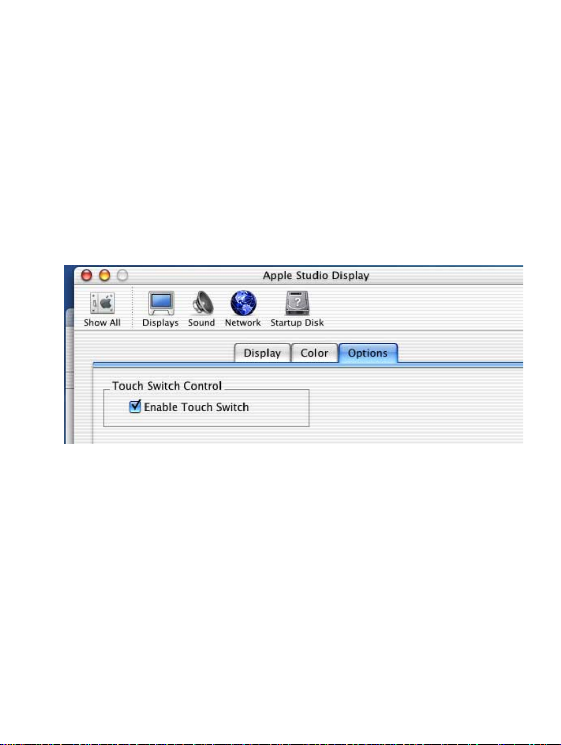
1. With the system booted and the Studio Display 15 attached, press and hold down the Command
and Shift keys, and continue to hold them down while you complete Step 2.
2. Touch the launch button on the left side of the display to open the Displays pane of System
Preferences. (You may also open the System Preferences from the Apple menu.)
3. Release the Command and Shift keys.
4. With the Display’s system preferences panel open, click the Options tab. Note: If the “Options” tab
appears, then the touch switch kit is already present. If the Options tab does not appear, and the
display is experiencing problems working in close proximity to some wireless devices, the touch
switch kit can be installed if necessary.
to determine whether the kit is required, follow the steps
2 - Studio Display 15” LCD ( ADC) Troubleshooting
General Information
Page 40
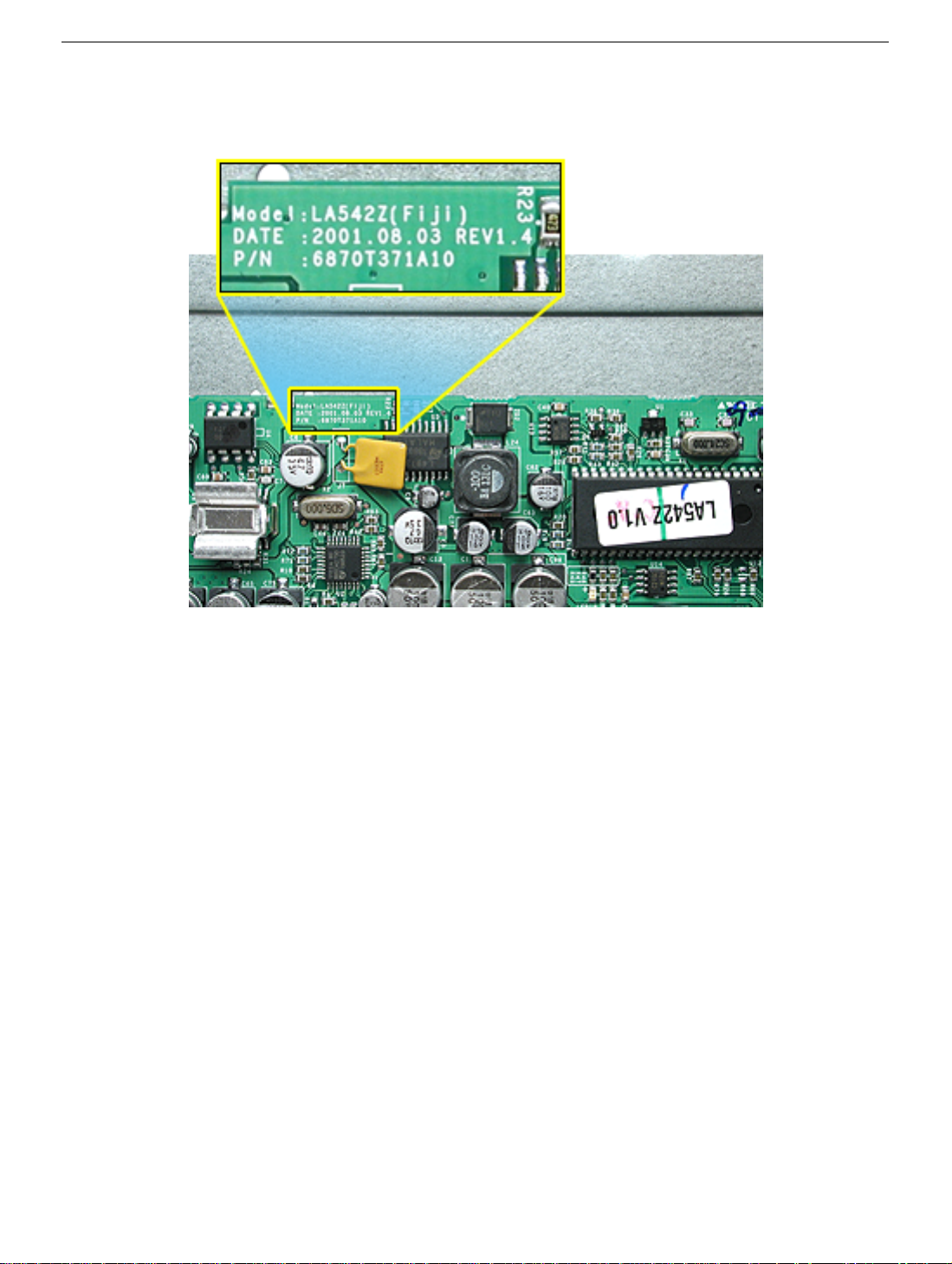
3. Main Board Identification: If the main pcb board shows Rev 1.4 (shown below) on the PCB silkscreen
then the touch switch kit features are already present. Note: Do not use the V1.0 information printed on
the large IC’s sticker to identify the board revision; use only the PCB silkscreen number.
4. Error codes: The Studio Display 15 will flash a repeating error code on the power LED if it detects a
backlight fault. The error code consists of two short flashes followed by a long flash, a pause, and then
the error repeats. When this error condition occurs, the problem could be bad bulbs, disconnected cable,
or a bad inverter. Test the bulbs by pulling them out of the display and plugging them directly into the
inverter. If they light, the bulbs are good. If they don’t light, try a known good bulb and try again. If the
bulb still doesn’t light, replace the inverter. Warning: The inverter board generates high voltage when
the display is plugged in. Do not touch the inverter board components, pins or connectors, when the
display is connected to the computer.
General Information
Studio Display 15” LCD ( ADC) - 3
Page 41

Symptom Charts
How to Use the Symptom Charts
The Symptom Charts included in this chapter will help you diagnose specific symptoms related to the
product. Because cures are listed on the charts in the order of most likely solution, try the cures in the
order presented. Verify whether or not the product continues to exhibit the symptom. If the symptom
persists, try the next cure.
Note: If you have replaced a module, reinstall the original module before you proceed to the next cure.
4 - Studio Display 15” LCD ( ADC) Troubleshooting
Symptom Charts
Page 42

No Power
1. Check J4 (see graphic below) input voltage. Do you measure +28V? I f yes, go on to the next step. If no,
make sure the ADC (Apple Display Cable) cable is securely connected. Disconnect the display cable and
check for bent pins on the display cable connector. Look for and carefully straighten any bent pins. Check
for bent pins on the video card, straighten any bent pins. Also, verify that you have a known good video
card in the computer. Turn on the computer to see if the symptom is gone.
2. Check IC U5 (pin 4) voltage. U5 is located to the right and slightly up (about 1/2”) from connector J4. Do
you measure +12V? If yes, go on to the next step. If no, replace the main board.
3. Check that the power button (touch switch) is working. Verify that the pins are not bent on the touch
switch. Refer to Knowledgebase article 58813 to determine whether the touch switches have been
software disabled. Reseat the connector at J9. If the power button touch switch is ok, go on to the next
step. If you still have no power, replace the power button (touch switch).
4. If you still have no power, recheck the ADC cable for bent pins, verify the connections to the main board
(J2, J4, J6).
5. Replace the main board.
No Power Symptom Charts
Studio Display 15” LCD ( ADC) - 5
Page 43

No Video
Dark Screen
1. Connect the display to a working computer. Shine a bright light onto the LCD to see if a faint image is
visible. If the backlighting system is not functioning (and for some reason there is no diagnostic code
on the LED) then the bright light should reveal a faint image of the desktop (or whatever is being
displayed at the time). Do you see a faint image? If yes, replace the backlight bulb(s). If you don’t see a
faint image, go on to the next step. Note: A high intensity light generates heat which could damage the
LCD display if left on for too long. Use caution to prevent damage to the LCD.
2. Check J3 (on the main board), pins 1 and 2 for +12V. Do you measure +12V? If yes, go on to the next
step. If no, replace the main board.
3. Check the inverter board connections. Reseat the connectors. If you still have no video, replace the
inverter board.
4. Check the connections on the ADC cable and TMDS connector (cable that connects to the flat panel
display). Reseat the connectors.
5. Check the connection on the main board cable at J2. This cable connects to the flat panel. Reseat the
cables.
6. Replace the LCD display.
6 - Studio Display 15” LCD ( ADC) Troubleshooting
Symptom Charts
Page 44

Partially Dim Screen
1. Plug the display into a known-good computer with a known-good video card and ADC display port. Boot
the computer.
2. The Studio Display 15 will flash a repeating error code on the power LED if it detects a backlight fault.
The error code consists of two short flashes followed by a long flash, a pause, and then the error
repeats. When this error condition occurs, the problem could be bad bulbs, disconnected cable, or a bad
inverter. Test the bulbs by pulling them out of the display and plugging them directly into the inverter. If
they light, the bulbs are good. If they don’t light, try a known good bulb and try again. If the bulb still
doesn’t light, replace the inverter. Warning: The inverter board generates high voltage when the display
is plugged in. Do not touch the inverter board components, pins or connectors, when the display is
connected to the computer.
No Video Symptom Charts
Studio Display 15” LCD ( ADC) - 7
Page 45

Touch Switch Not Working
1. Check if the touch switch is disabled (refer to Kbase article 58813).
2. Check the ADC cable. Replace/repair the ADC cable. Check the video card and ADC connector for
damage (bent pins).
3. Check the touch switches. The touch switches could be faulty (rare) or the touch switch cable(s) are
disconnected. Check the cables and touch switch and replace as needed. Usually if only one touch
switch is bad it’s probably the associated cable or touch switch. If neither touch switch works, it’s
probably the ADC cable or the main board having USB problems.
4. The USB circuit on the main board might be faulty. Use the Apple System Profiler to determine if the
display’s hub and the display are visible. If not, replace the main board.
8 - Studio Display 15” LCD ( ADC) Troubleshooting
Symptom Charts
Page 46

USB Devices Connected to Display Hub Not Working
1. Test the USB ports. Connect another USB device to one of the display’s USB ports. Use the Apple
System Profiler to determine if the display’s hub and the display are visible.
2. Does Apple System Profiler see the USB device you connected? If the hub shows up, but the attached
USB devices don’t, check the USB cable and its connectors that attach to the main board. If the hub or
attached devices don’t show up, there could be a problem with the ADC display cable (bent pins at the
ADC connector). If the problem still exists, go on to the next step.
3. Check connector J6 (on the main board). Make sure it’s connected and there are no bent pins.
4. Check Apple System Profiler again. Verify if the display’s USB hub is visible. If no, replace the main
board or replace the Apple Display Cable.
USB Devices Connected to Display Hub Not Work-
Studio Display 15” LCD ( ADC) - 9
Page 47

Pixel Anomalies
Note: Refer to KnowledgeBase article 22194 for the most current Pixel Anomaly information and
specifications.
Article 22194 defines the term “pixel anomaly”, explains why such anomalies occur, and describes what to
do if you feel your active matrix LCD panel has more than an acceptable number of pixel anomalies.
10 - Studio Display 15” LCD ( ADC) Troubleshoot-
Symptom Charts
Page 48

Pixel Anomalies Symptom Charts
Studio Display 15” LCD ( ADC) - 11
Page 49

Service Source
Views
Apple Studio Display 15" LDC (ADC)
© 2002 Apple Computer, Inc. All rights reserved.
Page 50
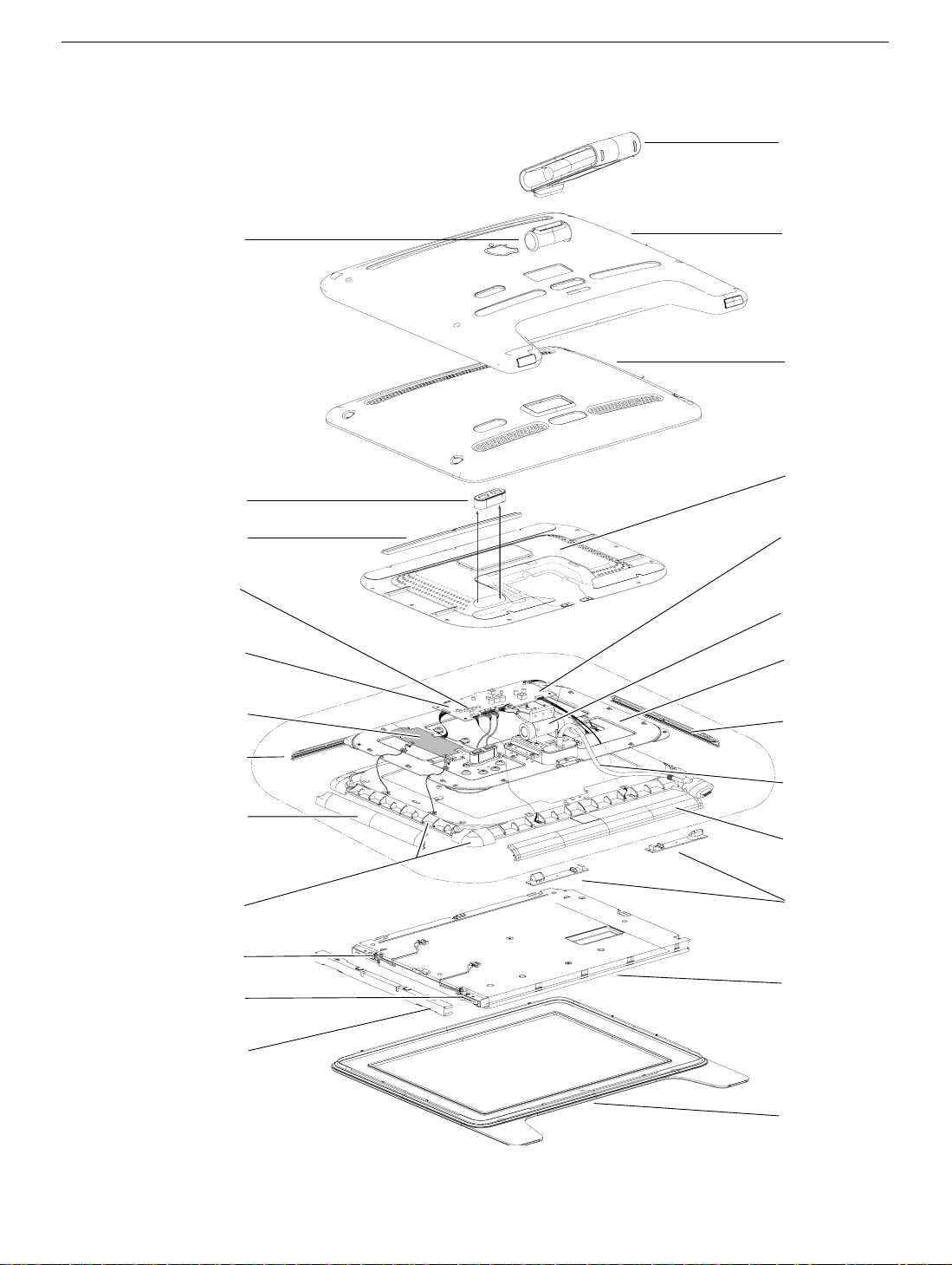
Exploded View
2
1
3
4
10
13
13
14
14
17
20
19
16
15
9
18
11
12
8
6
7
5
Foot Assembly
922-5621
Cover, Hinge
922-5622
Cover, USB Trim Ring
Cable, Main Board
922-5627
Rear Panel Clip
922-5626
Power Switch
922-5637
Main Board
922-5629
922-5696, Rev.2
Inverter Board
922-5632
Clip, Horizontal
922-5630
Clip, Vertical
922-5631
Bracket, Main Cradle
922-5634
Bulb, Upper
922-5644
Bulb, Lower
922-5645
Cover, Shield,
Backlight Bulbs
922-5592
Cover, Back
922-5623
Cover, Inner, Back
922-5624
Shield, EMI, LCD
922-5625
Cable,
Main B6-Adj Switch
922-5638
Hinge Assembly
922-5633
Chassis, Metal Frame
922-5628
Clip, Vertical
922-5631
Cable Main, ADC
922-5635
Clip, Horizontal
922-5630
Touch Switch
922-5636
922-5591, Rev.2
Display, LCD, 15"
661-2780
Apple Studio Display 15" LCD (ADC) Views
Bezel, Front, 15"
922-5590
 Loading...