


Model No. 831.299462
Serial No.
Find the serial number in the location shown below. Write the serial number in the space above for reference.
Serial
Number
Decal
SEARS, ROEBUCK AND CO. HOFFMAN ESTATES, IL 60179
 CAUTION
Read all precautions and instructions in this manual before using this equipment. Save this manual for future reference.
®
USER'S MANUAL
Patent Pending

 Visit our website at
www.proform.com
new products, prizes, fitness tips, and much more!

®
TABLE OF CONTENTS
IMPORTANT PRECAUTIONS . . . . . . . . . . . . . . . . . . . . . . . . . . . . . . . . . . . . . . . . . . . . . . . . . . . . . . . . . . . . . . . . .3 BEFORE YOU BEGIN . . . . . . . . . . . . . . . . . . . . . . . . . . . . . . . . . . . . . . . . . . . . . . . . . . . . . . . . . . . . . . . . . . . . . . .5 ASSEMBLY . . . . . . . . . . . . . . . . . . . . . . . . . . . . . . . . . . . . . . . . . . . . . . . . . . . . . . . . . . . . . . . . . . . . . . . . . . . . . . .6 OPERATION AND ADJUSTMENT . . . . . . . . . . . . . . . . . . . . . . . . . . . . . . . . . . . . . . . . . . . . . . . . . . . . . . . . . . . . .8 HOW TO FOLD AND MOVE THE TREADMILL . . . . . . . . . . . . . . . . . . . . . . . . . . . . . . . . . . . . . . . . . . . . . . . . . .19 TROUBLE-SHOOTING . . . . . . . . . . . . . . . . . . . . . . . . . . . . . . . . . . . . . . . . . . . . . . . . . . . . . . . . . . . . . . . . . . . . .20 CONDITIONING GUIDELINES . . . . . . . . . . . . . . . . . . . . . . . . . . . . . . . . . . . . . . . . . . . . . . . . . . . . . . . . . . . . . . .22 PART LIST . . . . . . . . . . . . . . . . . . . . . . . . . . . . . . . . . . . . . . . . . . . . . . . . . . . . . . . . . . . . . . . . . . . . . . . . . . . . . . .23 ORDERING REPLACEMENT PARTS . . . . . . . . . . . . . . . . . . . . . . . . . . . . . . . . . . . . . . . . . . . . . . . . . .Back Cover FULL 90-DAY WARRANTY . . . . . . . . . . . . . . . . . . . . . . . . . . . . . . . . . . . . . . . . . . . . . . . . . . . . . . . . . . .Back Cover
Note: An EXPLODED DRAWING is attached in the center of this manual.
2

IMPORTANT PRECAUTIONS
 WARNING: To reduce the risk of burns, fire, electric shock, or injury to persons, read the following important precautions and information before operating the treadmill.
1.It is the responsibility of the owner to ensure that all users of this treadmill are adequately informed of all warnings and precautions.
2.Use the treadmill only as described.
3.Place the treadmill on a level surface, with at least eight feet of clearance behind it. Do not place the treadmill on any surface that blocks air openings. To protect the floor or carpet from damage, place a mat under the treadmill.
4.Keep the treadmill indoors, away from moisture and dust. Do not put the treadmill in a garage or covered patio, or near water.
5.Do not operate the treadmill where aerosol products are used or where oxygen is being administered.
6.Keep children under the age of 12 and pets away from the treadmill at all times.
7.The treadmill should not be used by persons weighing more than 250 pounds.
8.Never allow more than one person on the treadmill at a time.
9.Wear appropriate exercise clothing when using the treadmill. Do not wear loose clothing that could become caught in the treadmill. Athletic support clothes are recommended for both men and women. Always wear athletic shoes. Never use the treadmill with bare feet, wearing only stockings, or in sandals.
10.When connecting the power cord (see page 8), plug the power cord into a surge suppressor (not included) and plug the surge suppressor into a grounded circuit capable of carrying 15 or more amps. No other appliance should be on the same circuit. Do not use an extension cord.
11.Use only a single-outlet surge suppressor that is UL 1449 listed as a transient voltage surge suppressor (TVSS). The surge suppressor must have a UL suppressed voltage rating of 400 volts or less and a minimum surge dissi-
pation of 450 joules. The surge suppressor must be electrically rated for 120 volts AC and 15 amps. To purchase a surge suppressor, see your local SEARS or call 1-800-366-7278 and order part number 146148.
12.Keep the power cord and the surge suppressor away from heated surfaces.
13.Never move the walking belt while the power is turned off. Do not operate the treadmill if the power cord or plug is damaged, or if the treadmill is not working properly. (See BEFORE YOU BEGIN on page 5 if the treadmill is not working properly.)
14.Never start the treadmill while you are standing on the walking belt. Always hold the handrails while using the treadmill.
15.The treadmill is capable of high speeds. Adjust the speed in small increments to avoid sudden jumps in speed.
16.The pulse sensor is not a medical device. Various factors, including the user's movement, may affect the accuracy of heart rate readings. The pulse sensor is intended only as an exercise aid in determining heart rate trends in general.
17.Never leave the treadmill unattended while it is running. Always remove the key, unplug the power cord and move the on/off switch to the off position when the treadmill is not in use. (See the drawing on page 5 for the location of the on/off switch.)
18.Do not attempt to raise, lower, or move the treadmill until it is properly assembled. (See ASSEMBLY on page 6, and HOW TO FOLD AND MOVE THE TREADMILL on page 19.) You must be able to safely lift 45 pounds (20 kg) in order to raise, lower, or move the treadmill.
19.Do not change the incline of the treadmill by placing objects under the treadmill.
20.When folding or moving the treadmill, make sure that the storage latch is fully closed.
3

21.When using i-FIT.com CD’s and videos, an electronic “chirping” sound will alert you when the speed and/or incline of the treadmill is about to change. Always listen for the “chirp” and be prepared for speed and/or incline changes. In some instances, the speed and/or incline may change before the personal trainer describes the change.
22.When using i-FIT.com CD’s and videos, you can manually override the speed and incline settings at any time by pressing the speed and incline buttons. However, when the next “chirp” is heard, the speed and/or incline will change to the next settings of the CD or video program.
23.Always remove i-FIT.com CD’s and videos from your CD player or VCR when you are not using them.
24.Inspect and tighten all parts of the treadmill regularly.
25.Never insert or drop any object into any opening.
26.DANGER: Always unplug the power cord immediately after use, before cleaning the treadmill, and before performing the maintenance and adjustment procedures described in this manual. Never remove the motor hood unless instructed to do so by an authorized service representative. Servicing other than the procedures in this manual should be performed by an authorized service representative only.
27.This treadmill is intended for in-home use only. Do not use this treadmill in any commercial, rental, or institutional setting.
 WARNING: Before beginning this or any exercise program, consult your physician. This is especially important for persons over the age of 35 or persons with pre-existing health problems. Read all instructions before using. SEARS assumes no responsibility for personal injury or property damage sustained by or through the use of this product.
SAVE THESE INSTRUCTIONS
The decals shown below have been placed on your treadmill. If a decal is missing, or if it is not legible, please call our toll-free HELPLINE to order a free replacement decal (see the front cover of this manual). Apply the decal in the location shown.
Note: This decal is shown at 38% of actual size.
4
BEFORE YOU BEGIN
Thank you for selecting the revolutionary PROFORM® 740CS treadmill. The 740CS treadmill combines advanced technology with innovative design to help you get the most from your exercise program in the convenience and privacy of your home. And when you’re not exercising, the unique 740CS can be folded up, requiring less than half the floor space of other treadmills.
For your benefit, read this manual carefully before using the treadmill. If you have additional questions, please call our toll-free HELPLINE at 1-800-736-6879,
Monday through Saturday, 7 a.m. until 7 p.m. Central Time (excluding holidays). To help us assist you, please note the product model number and serial number before calling. The model number of the treadmill is 831.299462. The serial number can be found on a decal attached to the treadmill (see the front cover of this manual for the location).
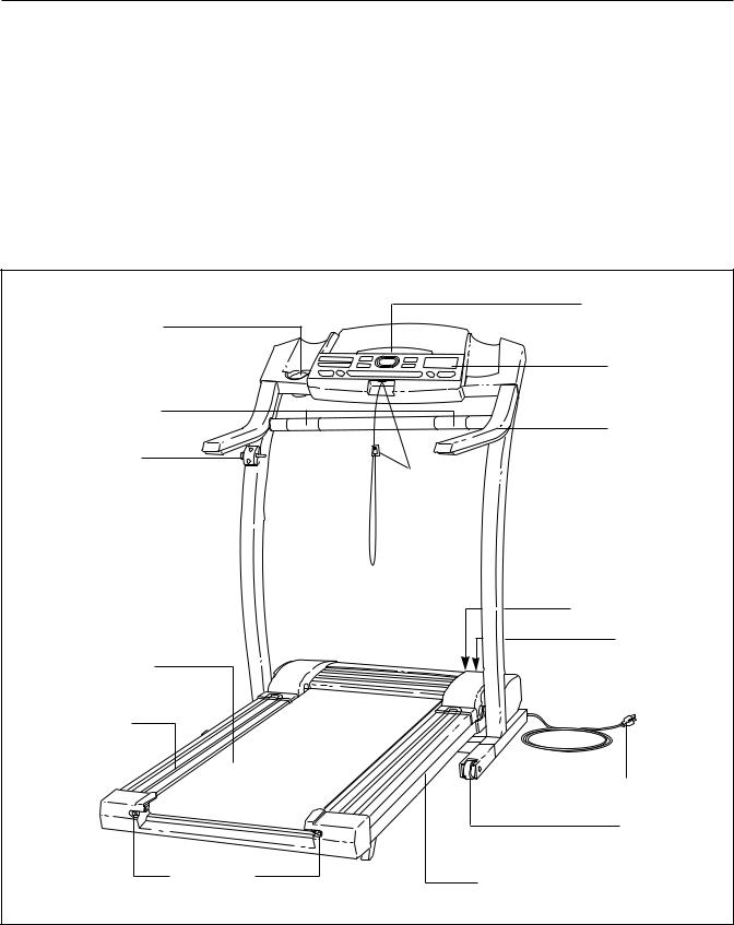
Before reading further, please review the drawing below and familiarize yourself with the parts that are labeled.
Water Bottle Holder (Bottle not included)
Pulse Sensor
Lock Knob
LEFT SIDE
Walking Belt
Foot Rail
Rear Roller
Adjustment Bolts
Book Holder
Console
Handrail
Key/Clip
RIGHT SIDE
On/Off Switch
Circuit
Breaker
Power Cord
Front
Wheel
Cushioned Walking Platform
5
ASSEMBLY
Assembly requires two people. Set the treadmill in a cleared area and remove all packing materials. Do not dispose of the packing materials until assembly is completed. Assembly requires your own Phillips screwdriver 
 , wire cutters
 , and rubber mallet
  .
.
Note: The underside of the treadmill walking belt is coated with high-performance lubricant. During shipping, a small amount of lubricant may be transferred to the top of the walking belt or the shipping carton. This is a normal condition and does not affect treadmill performance. If there is lubricant on top of the walking belt, simply wipe off the lubricant with a soft cloth and a mild, non-abrasive cleaner.
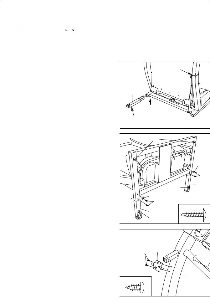
1.With the help of a second person, carefully raise the treadmill to the upright position.
While a second person tips the treadmill to one side slightly and holds it, insert one of the Extension Legs (103) into the treadmill as shown. Make sure that the Extension Leg is turned so the Base Pad (97) is on the bottom.
Next, tip the treadmill to the other side and insert the other Extension Leg (not shown) in the same way. Lower the side of the treadmill so that both Extension Legs (103) are resting flat on the floor. Cut the Wire Tie off the Upright (82).
2.With the help of a second person, carefully lower the treadmill frame and then tip the Uprights (82) down as shown. Make sure that the Extension Legs (103) remain in the Uprights.
Attach each Extension Leg (103) with two of the four Screws (101) and a Base Pad (126) as shown.
Note: One replacement Base Pad (126) and Spacer (not shown) are included. If a Base Pad becomes worn and needs to be replaced, use the replacement Base Pad. If a Thick Base Pad (97) needs to be replaced, use the replacement Base Pad with the Spacer.
3.With the help of a second person, carefully tip the Uprights (82) back to the vertical position.
Attach the Latch Assembly (9) to the left Upright (82) with the two 1/2” Screws (89).
1 |
Wire Tie |
|
|
||
|
82 |
|
103 |
|
|
97 |
|
|
2 |
97 |
|
|
||
|
126 |
|
|
101 |
|
|
103 |
|
|
97 |
|
82 |
126 |
|
101 |
||
|
||
|
101 |
|
|
103 |
|
|
97 |
|
3 |
|
|
89 |
9 |
|
89 |
82 |
|
|
6
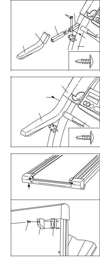
4.Insert a Handrail Extension (85) into the left post as shown. Align the holes in the Handrail Extension with the holes in the post. If necessary, tap the Handrail Extension with a rubber mallet to fully insert it. Next, attach the Handrail Extension by tightening three Small Screws (76) into the indicated holes. Note that the hole in the left side of the post is not used. Note: If there is only one hole in the top of the post, tighten the third Small Screw into the hole in the left side of the post.
Identify the Left Foam Grip (110), which has a large cutout in the right side. Slide the Left Foam Grip as far as possible onto the post on the left Upright (82). It may be helpful to apply soapy water to the Handrail Extension (85).
5.Make sure that the front edge of the Left Foam Grip (110) is under the Console Base (87) as shown. Tighten a Small Screw (76) into the side of the Left Foam Grip as shown.
Attach the Right Foam Grip (not shown) and the other Handrail Extension (not shown) as described in step 4 and this step.
There may be extra screws after assembly is completed.
6.Refer to drawing 6a. Locate the left Rear Foot (59) on the treadmill. If the left Rear Foot touches the floor, go to step 7. If there is a space between the left Rear Foot and the floor, follow the instructions below.
Hold the treadmill firmly with both hands, and raise the treadmill to the storage position as described on page 19.
Refer to drawing 6b. Using a phillips screwdriver, remove the Screw (60), the right Rear Foot (59), and the Rear Foot Spacer (11) from the treadmill. Reattach the right Rear Foot without the Rear Foot Spacer. Hold the treadmill with both hands, and lower the treadmill as described on page 19.
Check the left Rear Foot (59 [see drawing 6a]). If the left Rear Foot is still off the floor, raise the treadmill and remove the left Rear Foot. Snap the Rear Foot Spacer (11) onto the left Rear Foot and reattach the left Rear Foot and the Rear Foot Spacer. Carefully lower the treadmill.
4 |
|
|
|
|
|
76 |
Post |
|
|
|
|
|
|
85 |
|
Cutout |
|
|
|
110 |
|
|
76 |
|
|
82 |
|
|
|
|
|
|
|
|
76 |
5 |
|
87 |
|
|
|
|
|
|
76 |
|
|
|
110 |
|
|
|
|
|
76 |
6a |
|
|
|
59 |
|
|
|
6b |
|
|
|
60 |
59 |
|
|
|
11 |
|
|
|
|
|
7.Make sure that all parts are tightened before you use the treadmill. Keep the included allen wrench in a secure place. The allen wrench is used to adjust the walking belt (see page 21). To protect the floor or carpet from damage, place a mat under the treadmill.
7
OPERATION AND ADJUSTMENT
THE PERFORMANT LUBETM WALKING BELT
Your treadmill features a walking belt coated with PERFORMANT LUBETM, a high-performance lubricant.
IMPORTANT: Never apply silicone spray or other substances to the walking belt or the walking platform. Such substances will deteriorate the walking belt and cause excessive wear.
HOW TO PLUG IN THE POWER CORD
 DANGER: Improper connection of the equipment-grounding conductor can result in an increased risk of electric shock. Check with a qualified electrician or serviceman if you are in doubt as to whether the product is properly grounded. Do not modify the plug provided with the product—if it will not fit the outlet, have a proper outlet installed by a qualified electrician.
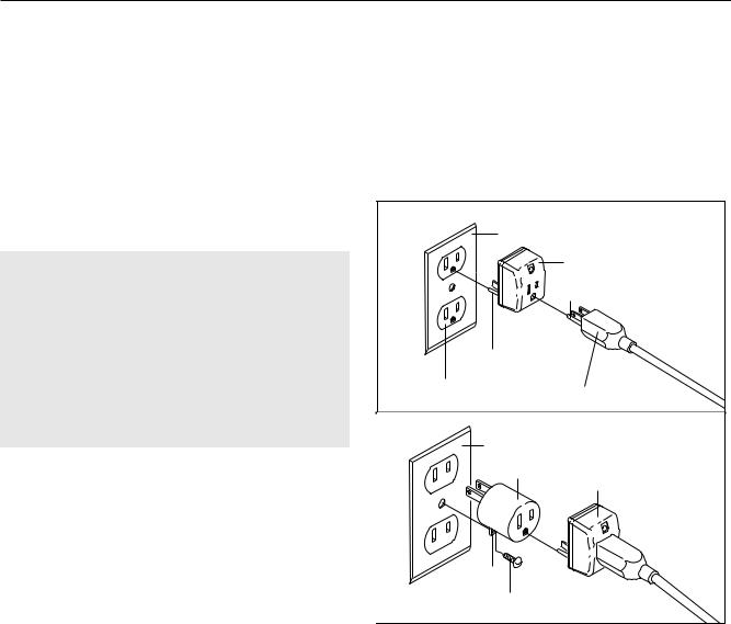
Your treadmill, like any other type of sophisticated electronic equipment, can be seriously damaged by sudden voltage changes in your home’s power. Voltage surges, spikes, and noise interference can result from weather conditions or from other appliances being turned on or off. To decrease the possibility of your treadmill being damaged, always use a surge suppressor with your treadmill (see drawing 1 at the right).
To purchase a surge suppressor, see your local SEARS or call toll-free 1-800-366-7278 and order part number 146148. Use only a single-outlet surge suppressor that is UL 1449 listed as a transient voltage surge suppressor (TVSS). The surge suppressor must have a UL suppressed voltage rating of 400 volts or less and a minimum surge dissipation of 450 joules. The surge suppressor must be electrically rated for 120 volts AC and 15 amps.
This product must be grounded. If it should malfunction or break down, grounding provides a path of least resistance for electric current to reduce the risk of electric shock. This product is equipped with a cord having an equipment-grounding conductor and a grounding plug. Plug the power cord into a surge suppressor, and plug the surge suppressor into an appropriate outlet that is properly installed and grounded in accordance with all local codes and ordinances. Important: The treadmill is not compatible with GFCI-equipped outlets.
This product is for use on a nominal 120-volt circuit, and has a grounding plug that looks like the plug illustrated in drawing 1 below. A temporary adapter that looks like the adapter illustrated in drawing 2 may be used to connect the surge suppressor to a 2-pole receptacle as shown in drawing 2 if a properly grounded outlet is not available.
1
Grounded Outlet Box
|
Surge Suppressor |
|
Grounding Pin |
Grounding Pin |
|
Grounded Outlet |
Grounding Plug |
|
|
2
Grounded Outlet Box
Adapter
Surge Suppressor
Lug
Metal Screw
The temporary adapter should be used only until a properly grounded outlet (drawing 1) can be installed by a qualified electrician.
The green-colored rigid ear, lug, or the like extending from the adapter must be connected to a permanent ground such as a properly grounded outlet box cover. Whenever the adapter is used it must be held in place by a metal screw. Some 2-pole receptacle outlet box covers are not grounded. Contact a qualified electrician to determine if the outlet box cover is grounded before using an adapter.
8
 Loading...