


Issue date 12-01 288F0460
BPV 655
High-Power FM/AM/CD Receiver with Detachable Face
Autoradio FM/AM à Lecteur CD de Forte Puissance et à Face Amovible Receptor FM/AM/Reproductor de CD de Alta Potencia y con Panel Extraíble
Rádio FM/AM/CD de Alta Potência com Face Removível
Robert Bosch Corporation Sales Group — Blaupunkt Division
2800 South 25th Avenue, Broadview, Illinois 60155 http://www.blaupunktUSA.com/
ENGLISH
FRANÇAIS
PORTUGUÊS ESPAÑOL
BPV655_Cover |
1 |
1/10/02, 5:49 PM |
FCC WARNING |
Precautions |
Handling the Front Panel |
This equipment has been tested and found to comply with the limits for a Class B device, pursuant to Part 15 of the FCC Rules. These limits are designed to provide reasonable protection against harmful interference in a residential installation. This equipment generates, uses, and can radiate radio frequency energy, and, if not installed and used in accordance with instructions, may cause harmful interference with radio communications. However, there is no guarantee that radio interference will not occur in particular installation. If this equipment does cause harmful interference to radio or television reception, which can be determined by turning the equipment off and on, the user is encouraged to consult the dealer or an experienced radio/TV technician for help.
You are cautioned that any changes or modifications not expressly approved in this manual could void your authority to operate this equipment.
•Avoid installing the unit where it would be subject to high temperatures, such as in direct sunlight or a hot air stream from the heater, or where it would be subject to dust, dirt, or excessive vibration.
•Do not turn on the unit if the temperature inside the car is very high. Always cool down the unit before usage. Parking your car in direct sunlight will result in a temperature rise.
•If the unit does not turn on, check the connections first. Then check whether the fuse at the back of the unit is blown.
•Carefully read this manual before using the unit. If you encounter any problems that are not covered in this manual, please consult the dealer where you purchased the unit or the dealer nearest to you.
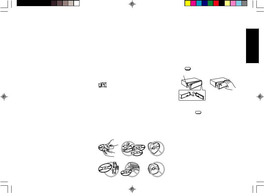
•This unit has been designed specifically for playback of compact discs bearing the following mark. Other discs cannot be played.
Features
•Detachable front panel
•Built-in power amplifier (max. output : 55W × 4ch)
•FM/AM PLL Synthesizer tuner
•30 Station preset memory
•Travel Store / Scan tuning
Handling Compact Discs
•Be careful when removing a compact disk after the playback is completed because the disk may be extremely hot.
•Do not use non-conventional discs such as heart-shaped, octangonal discs, etc. The player could be damaged.
•Do not expose compact discs to direct sunlight or any heat source.
•Check all compact discs before playing, and discard cracked, scratched or warped discs.
•Wipe dirty or damp discs outward from the centre with a soft cloth.
•Do not use any solvents such as commercially available cleaners, antistatic spray, or thinner to clean the compact discs.
Attaching the Front Panel |
|
|
Place the right hand side of the front panel so that the parts |
ENGLISH |
|
A of the front panel are engaged with the parts B of the unit |
||
|
||
as shown below. Then push the left hand side of the front |
|
|
panel until it is securely locked. |
|
|
Detaching the Front Panel |
|
|
Remove the CD from the unit, if any, and turn off the power of |
|
|
the unit. |
|
|
Press the REL to unlock the front panel from the unit. Grasp |
|
|
the front panel as shown below and remove it from the unit. |
|
Security
To avoid theft or loss of the front panel, you can inactivate the release button REL by installing the screw provided.
1. Unscrew the bolt marked * at the left front side of the unit. (See diagram above)
2. Attach the front panel.
3. Select a locking screw from the mounting hardware (See page 7) and screw it into the same hole to fasten the front panel.
Notes
•Do not press hard on the front panel when affixing it to the unit. No more than light to moderate pressure should be needed.
•Make sure there is no dust or dirt on the electrical terminals on the back of the front panel as this could cause intermitent operation or other malfunctions.
E-1
BPV655(EN)_body |
1 |
1/10/02, 5:49 PM |
|
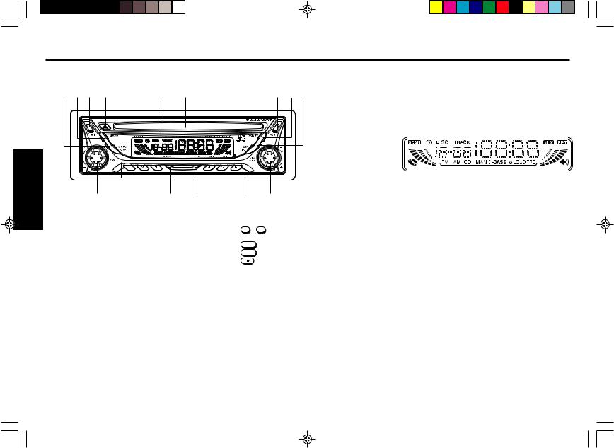
Identification of Controls |
|
|
|
|
|
|
|
|
|
||||
ENGLISH |
Front Panel |
|
|
|
|
|
LCD Display |
|
|
|
|
|||
1 |
2 |
3 |
4 |
5 |
6 |
7 |
8 |
9 |
|
|
|
|
|
|
|
|
|
|
|
|
|||||||||
|
|
|
|
|
|
|
|
|
1 |
2 |
3 |
4 |
5 |
6 |
|
|
|
|
|
FMlll AMll CDC MAN X-BASS lo LOUD TRE |
|
|
|
|
|
|
|
|
|
14 |
13 |
12 |
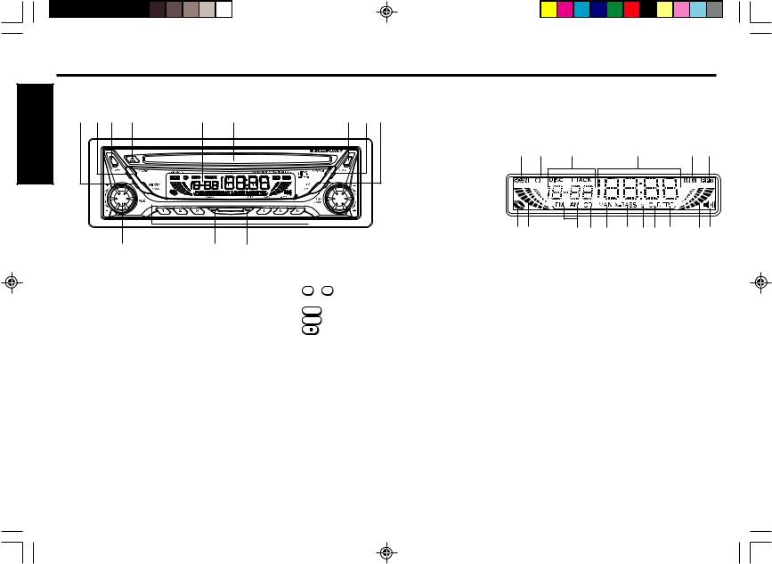
1MUTE/SENS button
Mutes the sound. Switches the seek sensitivity between local and distance.
2AUDIO button
Audio control selector; Bass, Treble, Loudness, X-BASS, Balance, Fader & Level Meter.
3REL button
Releases the detachable front panel.
4Eject  button
Ejects the CD. Reset the unit.
5LCD Display window
6CD insertion slot
Insert the CD here.
7PWR button
Turns the power of the unit on or off.
8DISPLAY button
Display selector. Display priority setting.Clock adjustment.
9SC/PS button
Scan tuning. Preset scan tuning. Scan play in CD mode.
10TUN/TRK dial
Used to tune in to the desired station.
|
|
|
|
|
|
|
|
|
|
|
|
|
|
|
|
|
|
|
|
|
|
17 16 |
15 |
|
14 |
13 |
12 |
11 10 |
9 |
8 |
7 |
||
11 |
10 |
|
|
|
|
|
|
|
|
|
|
|
|
|||
11 PRESET MEMORY button |
1 |
SCAN indicator |
|
|
|
|
|
|
|
|
||||||
During radio reception : |
2 |
STEREO signal indicator |
|
|
|
|
|
|
||||||||
1 - 6 |
; |
For Preset memory |
3 |
DISC/TRACK Number indicator |
|
|
|
|
|
|||||||
During CD mode : |
4 |
Main display section |
|
|
|
|
|
|
|
|||||||
4/MIX |
; |
For Mix play |
5 |
MIX Mode indicator |
|
|
|
|
|
|
|
|||||
5/RPT |
; |
For Repeat play |
6 |
RPT Mode indicator |
|
|
|
|
|
|
|
|||||
6/ |
; |
For Pause |
7 |
X-BASS level indicator |
|
|
|
|
|
|
|
|||||
12 CD button |
|
|
|
8 |
R-ch Level Meter |
|
|
|
|
|
|
|
|
|||
Selects the operating source (CD, CD changer or AUX). |
9 |
Treble indicator |
|
|
|
|
|
|
|
|
||||||
13 BAND button |
|
10 |
LOUD indicator |
|
|
|
|
|
|
|
|
|||||
Selects the AM/FM band & Travel store. |
11 lo(Local) indicator |
|
|
|
|
|
|
|
|
|||||||
14 VOL dial |
|
|
|
12 |
X-BASS/BAS indicator |
|
|
|
|
|
|
|
||||
Adjusts the volume level and audio control. |
13 |
MAN(Manual tuning) indicator |
|
|
|
|
|
|||||||||
|
|
|
|
|
14 |
CD indicator |
|
|
|
|
|
|
|
|
|
|
|
|
|
|
|
15 |
AM/FM indicator |
|
|
|
|
|
|
|
|
||
|
|
|
|
|
16 |
L-ch Level Meter |
|
|
|
|
|
|
|
|
||
|
|
|
|
|
17 |
DISC IN indicator |
|
|
|
|
|
|
|
|
||
E-2
BPV655(EN)_body |
2 |
1/10/02, 5:49 PM |
General Operations
Turning the power On/Off
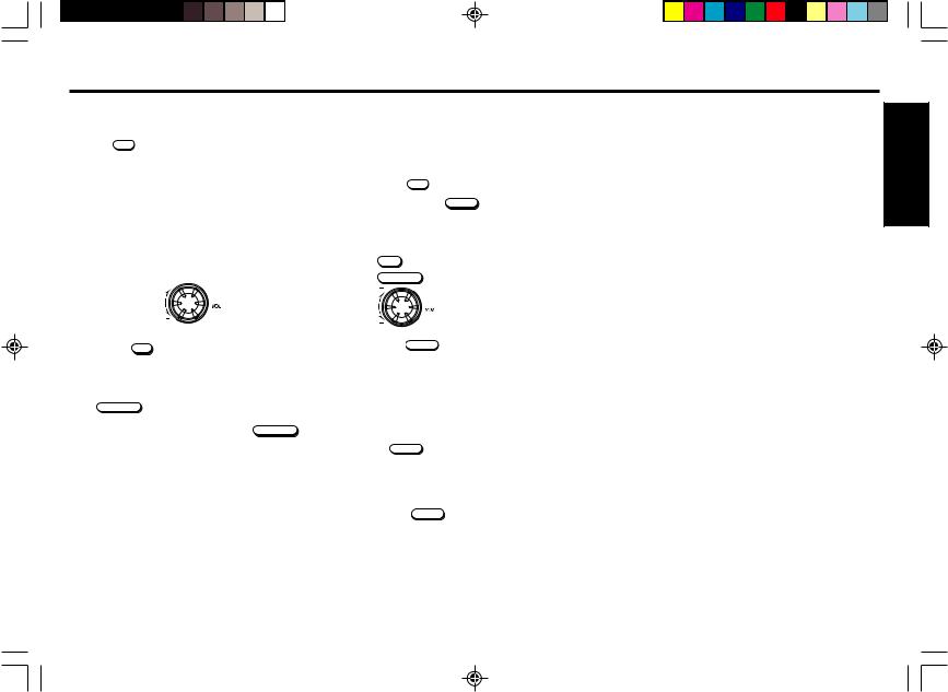
Press the PWR to turn the unit On or Off.
Volume Level Control and Memory
Rotate the VOL dial to adjust the volume.
It is also possible to set turn-on volume level by following the procedure explained below.
1. Rotate the VOL dial until it is set at the required volume.
Volume up
Volume down
2. Press the PWR for two or more seconds. The power will be switched off and the current volume level recorded.
Muting the sound
Press MUTE / SENS .
The R-ch/L-ch Level Meter flashes.
To restore the previous volume level, press MUTE / SENS again.
Setting the Clock |
|
|
The clock uses a 12-hour display system. |
ENGLISH |
|
1. |
Turn the ignition key to the ON position. |
|
2. |
Press the PWR to turn on the unit. |
|
3. |
|
|
Press and hold the DISPLAY for more than two seconds to |
|
|
|
enter the Clock setting mode. |
|
4. Use the following buttons and dial to set the clock. (The blinking section can be adjusted.)
AUDIO |
: To activated Hour blink |
MUTE / SENS |
: To activated Minute blink |
|
: Adjust the Hour and minute |
5. Press the DISPLAY |
momentarily to complete the Clock set- |
ting mode. |
|
Ignition-off Clock Recall
The display will illuminate showing the time and then automatically shut off after 5 seconds.
Press the |
DISPLAY |
while the ignition switch is in the “ OFF ” |
|
||
position. |
|
|
Display Priority Selector
Each time the DISPLAY is pressed, the display window will change as shown below ;
•Radio mode
Frequency and Clock.
•CD mode
Elapsed time and Clock.
E-3
BPV655(EN)_body |
3 |
1/10/02, 5:49 PM |

|
Adjusting the Sound Characteristics |
|
ENGLISH |
1. Press the AUDIO |
to select the desired adjustment mode |
as follows; |
|
|
|
|
|
|
BASS 0 |
|
|
TREBLE 0 |
|
|
LOUD OFF (LOUDNESS) |
|
|
X-BASS 0 |
|
|
L0 R0 (BALANCE) |
|
R0 F0 (FADER)
LE Lo (LEVEL METER)
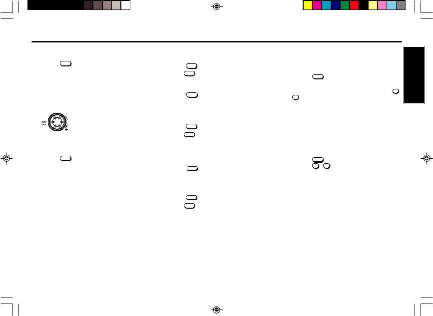
2. Rotate the VOL dial to adjust the selected item.
Use the following tables as a guide for adjusting the settings in each mode.
Adjust within 5 seconds after selecting the item. After 5 seconds, the unit returns to previous indication.
Adjustment Range
BASS |
BASS –5 |
|
BASS 5 |
|
|
|
|
||
TREBLE |
TREBLE –5 |
TREBLE 5 |
||
|
|
|
||
LOUDNESS |
LOUD OFF |
LOUD ON |
||
|
|
|
||
X-BASS |
X-BASS 0 |
X-BASS 4 |
||
|
|
|
||
BALANCE |
L9 R0(Full left) |
L0 R9(Full right) |
||
|
|
|
||
FADER |
R9 F0(Full rear) |
R0 F9(Full front) |
||
|
|
|
|
|
LEVEL METER |
OFF |
Lo (Normal) |
Hi (High) |
|
|
|
|
|
|
Tip
Settings for BASS, TREBLE, LOUDNESS and XBASS can be made to each of the following modes independently:
FM, AM, CD.
E-4
BPV655(EN)_body |
4 |
Enhancing the bass sound
For extended bass centered @ 72Hz, Blaupunkt’s X-BASS function can be set for either each band and CD mode.
You can select :
•X-BASS 1 : Enhanced BASS level (low).
•X-BASS 2 : Enhanced BASS level (Middle).
•X-BASS 3 : Enhanced BASS level (High).
•X-BASS 4 : Enhanced BASS level (Very high).
•X-BASS 0 : No BASS enhanced.
Press the AUDIO to display the “ X-BASS ” on the display window. Each time you rotate the VOL dial, the current mode appears on the display window and the mode change as fol-
lows:
X-BASS 0 (No display)
X-BASS 1
X-BASS 2
X-BASS 3
X-BASS 4
Note
Reduce XBASS level if your combination of speakers and addon amplifiers sound distorted at the preferred sound level.
Level Meter Sensitivity selection
The sensitivity of the level meter display can be switched.
You can select :
• OFF (No indication)
• Low |
: Normal (Low) sensitivity. |
• High |
: High sensitivity. |
1. Press the AUDIO to display the “ LE Lo ” on the display window.
2. Rotate the VOL dial to select the desired meter sensitiv-
ity.
: OFF
: Lo
: Hi
1/10/02, 5:49 PM
Radio Reception
Seek Tuning
1. Press the BAND to select the desired AM or FM band. FM I FM II FM III AM I AM II
(FM III & AM II are Travel Store bands.)
2. Rotate the TUN/TRK dial to tune in stations. Tuning automatically stops at a broadcasting frequency.
When tuned in to FM stereo broadcasting stations, the “ ” stereo signal indicator will appear on the display window.
: Lower Frequency.
: Higher Frequency.
Manual Tuning
1. Press the BAND to select the desired AM or FM band.
2. Rotate and hold the TUN/TRK dial for more than 0.5 second to activate the manual tuning mode.
“ MAN ” indicator will appear on the display window. Rotate again to tune in to stations.
After 4 seconds of completing Manual Tuning, the tuning control will revert to the Seek Tuning mode.
Scan Tuning
1. |
Press the |
BAND |
to select the desired AM or FM band. |
2. |
Hold the |
SC/PS |
pressed for less than 2 seconds. |
|
The unit will scan the selected band for stations and the |
||
|
unit will stop at each station for 8 seconds, before con- |
||
|
tinuing to the next station. |
||
|
Press the |
SC/PS |
again to stop Scan Tuning and remain |
|
this on the selected frequency. |
||
Preset Scan Tuning |
|||
1. |
Press the |
BAND |
to select the desired AM or FM band. |
2. |
Hold the |
SC/PS |
pressed for more than 2 seconds. |
The unit will scan preset memory for the 12 stations from the AM I/AM II band or the 18 stations from the FM I/FM II/FM III bands. The unit will stop at each preset station for 8 seconds, before continuing to the next preset station.
Press the SC/PS again to stop Preset Scan Tuning and remain this on the selected frequency.
Memorizing Stations Automatically (Travel Store)
1. |
Press the |
BAND |
to select the desired AM or FM band. |
2. |
Hold the |
BAND |
pressed for longer than 2 seconds. |
Up to 6 stations with strong signals will be automatically stored in preset memory for the selected band.
If the radio is in FM I or FM II, it switches to FM III. If the radio is in AM I, it switches to AM II.
Note
This function is available for FM III and AM II.
Memorizing Only the Desired Stations |
|
|
|||
You can store up to 6 stations on each band (18 for FM I, FM |
ENGLISH |
||||
II and FM III, 12 for AM I and AM II) in the order of your |
|||||
|
|||||
choice. |
|
|
|
||
1. |
Press the BAND to select the desired band. |
|
|
||
2. |
Rotate the TUN/TRK dial to tune in stations. |
|
|
||
3. |
Press and hold the desired preset memory button 1 |
- |
|
||
|
6 |
for about 2 seconds until the frequency indicator |
|
||
|
flashes twice. |
|
|
||
|
The number of the pressed preset memory button ap- |
|
|||
|
pears on the display window. |
|
|
||
Note
If when you store another station on the same preset number button, the previously stored station is replaced with new one.
Receiving the Memorized Stations
1. |
Press the |
BAND |
to select the desired AM or FM band. |
2. |
Press the |
1 - |
6 momentarily. |
Local/Distant (LO/DX) Selection
This feature is used to select the signal strength at which the radio will stop during Seek Tuning.
Press the  for more than 2 seconds to select the Local setting and only strong (local) stations will be received. The “ lo ” indicator appears on the display window.
Pressing for more than 2 seconds again will select the Distant setting and the radio will stop at a wider range of signals, including weaker more distant stations. The “ lo ” indicator will go out on the display window. DX is the suggested default setting.
E-5
BPV655(EN)_body |
5 |
1/10/02, 5:50 PM |
CD Operations
ENGLISH |
Playing the CD player |
|
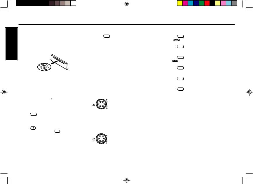
Loading Discs |
||
|
||
|
Insert the disc into the CD insertion slot with the labeled side |
|
|
facing up. |
|
|
Playback begins automatically. |
|
|
Labeled side up |
Stopping Playback
Press the BAND to select the radio reception (FM I, FM II, FM III or AM I, AM II).
Ejecting Discs
Press the  to eject the disc.
Notes
•The unit will turn on automatically when a CD is inserted if the ignition switch is ‘‘ON’’.
•When the disc is ejected from the CD slot, remove it within 10 seconds; otherwise, the disc will be reloaded automatically.
Scan Play
Press the |
SC/PS |
during CD mode. |
The ‘‘ |
’’ indicator appears in the display window. This |
|
will play the first 10 seconds of all the tracks on the disc. |
||
Press the |
SC/PS |
again to cancel this feature. |
Repeat Play |
|
|
Press the |
5/RPT |
during CD mode. |
The ‘‘ |
’’ indicator appears in the display window and the |
|
current track is played repeatedly. |
||
Press the |
5/RPT |
again to cancel this feature. |
Mix Play
NEVER Insert a 3-inch CD!
This unit is designed for playback of standard 5-inch CD’s only. Do not attempt to use 3-inch CD singles in this unit, either with or without an adaptor, as damage to the player and/or disc may occur.
Tips
• When a CD is loaded, the  on the display remains lit.
Listening to a disc that is already loaded
Press the |
CD to select the CD mode. |
Playback begins automatically. |
|
Pausing Playback |
|
Press the |
6/ . |
To resume playback, press the 6/ 

 again.
Track Search
Rotate the TUN/TRK dial during CD mode. Track numbers appear in the display window.
:Playback starts from the beginning of the current track. Rotate again to play the previous track.
:Playback starts from the beginning of the next track.
Cue / Review
Rotate and hold the TUN/TRK dial. Release when you have found the desired point.
: To search backward.
Press the 4/MIX during CD mode.
The ‘‘  ’’ indicator appears in the display window.
All the tracks on the current disc are played in random order. Press the 4/MIX again to cancel this feature.
: To search forward.
E-6
BPV655(EN)_body |
6 |
1/10/02, 5:50 PM |
Installations
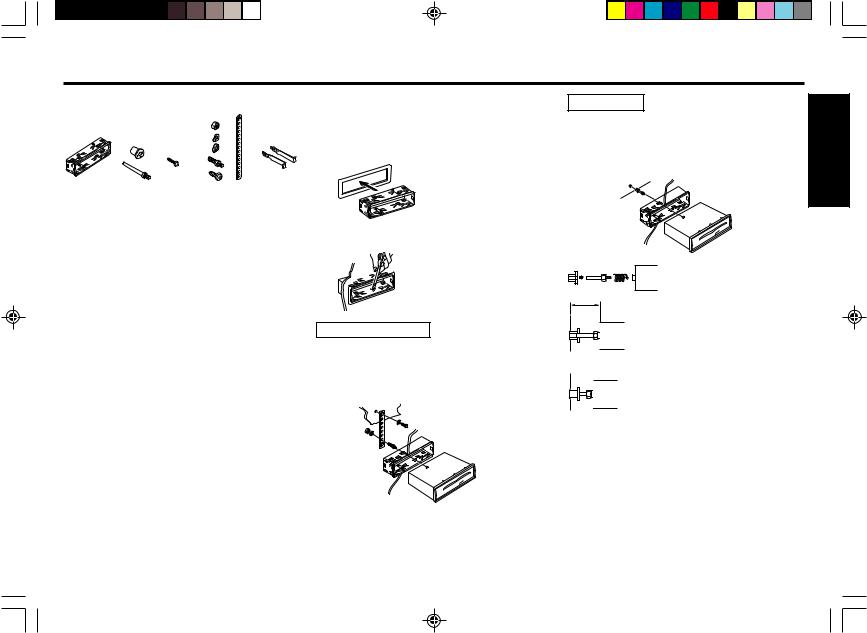
Supplied Mounting Hardware
Sleeve |
Bushing, |
Locking |
Mounting Strap |
Release |
|
Screw |
screw |
and Screw |
Keys |
||
|
Precautions
•Be sure to detach the front panel before you start installing the unit.
•Choose the mounting location carefully so that the unit will not interfere with the normal driving operations of the driver.
•Use only the supplied mounting hardware for a safe and secure installation.
•When mounting the unit in a car, keep the unit as level as possible. If the unit must be mounted at an angle, due to the design of the vehicle, make sure that the unit does not tilt upward by more than 30°.
Mounting Example
Installation in the dashboard.
1. Install the sleeve in the dashboard.
2. Select and bend the appropriate tabs to hold the sleeve firmly in place.
Bushing Use |
ENGLISH |
||
3. |
As shown in the figure below, securely fasten the |
||
|
|||
|
screw, which has been inserted into the bushing to |
|
|
|
the rear of the set. |
|
|
|
Fire wall |
|
|
Mounting Strap Use
3. Attaching the Mounting Strap to the underside of the dash board, using screw.
Attach the back of the unit to the Mounting Strap using the support stem bolt and hardware.
Fire wall
The distance to the fire wall varies due to the type of the car. Be sure to secure the unit by properly inserting the bushing.
Caution
Insufficient fastening of the screw may cause some CD’s to skip.
* Warning
Failure to properly install the Mounting Strap or rear support Bushing is a major cause of CD skipping. Without these securing devices, the chassis of the CD receiver is able to move up & down whenever the road has imperfections and CD skipping results.
Note
Some Japanese/Asian vehicles such as TOYOTA & NISSAN do not require use of the sleeve and trim ring assembly.
To secure the replacement radio use the O.E.M. brackets and mounting screws. These brackets will align with the threaded
screw holes found on each side of the new radio.
E-7
BPV655(EN)_body |
7 |
1/10/02, 5:50 PM |
|
Connections |
|
|
Warning |
Connection procedure |
ENGLISH |
• To prevent short circuit, remove the key from the ignition |
|
and disconnect the battery’s (–) terminal. |
|
|
|
|
|
|
• This unit is designed for negative ground 12 V DC operation |
|
|
only. You can not use it for 24 V or other types of car batter- |
|
|
ies. |
|
|
Connection procedure |
|
|
Caution |
|
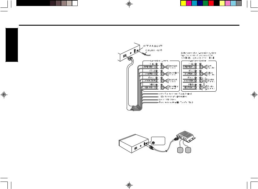
•DO NOT connect any speaker wires to the metal body or chassis of the vehicle.
•DO NOT connect the speaker common (–) wires to each other.
•Connect each speaker wire directly to each speaker terminal.
•All speaker common (–) wires must remain floating.
ie. No common connections or connection to vehicle grd.
•Connect each pair of speaker leads only to a single speaker (or speaker system) that has an impedance of least 4 ohms, as well as 55-watt power-handling capability.
•Do not connect speaker leads to any inputs on external amplifiers. This will cause damage to the internal amplifier of this unit.
1Make sure the car’s ignition key has been removed.
2Disconnect the negative (–) terminal of the car’s battery.
3Connect the wiring harness wires in the following order : Ground wire (Black), +12V Constant Power Supply (Yellow), +12V Accessory/Switched (Red) and Power Antenna/Amplifier Turn On (Blue), and tape each so they do not come in contact with each other.
4Connect the speaker wires of the wiring harness.
5Connect the car’s antenna terminal to the antenna socket of the unit.
6Connect the detachable wire harness to the unit.
7Reconnect the negative (–) terminal of the car’s battery.
8Start the car’s engine.
9Make sure the unit operates properly.
E-8
Preamp Out/Line Out Connections
• Since this unit has Line Level Outputs, you can use an amplifier to upgrade your vehicle stereo system.
RCA Line-out Jacks
 White (Left)
Red (Right)
External Amplifier
Rear Speaker
RCA Line-out Jacks (For Rear Speakers)
•Connect a patch cable (not supplied) from the White (left rear channel) and Red (right rear channel) RCA line output jacks of the unit to the line input terminals of the external amplifier.
BPV655(EN)_body |
8 |
1/10/02, 5:50 PM |
Maintenance
Replacing the Fuse
If the fuse is blown, check the power connection first and then replace the fuse. If the fuse blows again under normal conditions, the unit may be defective.
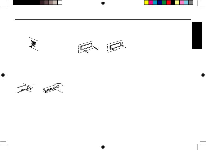
Removing the Unit
Use the supplied release keys when you need to remove the unit from the car.
Insert them into the unit as shown below. This will unlock the unit from the sleeve, allowing for removal of the unit.
Back of the unit
Warning
Use only a fuse with the specified amperage (10 A).
Use of another type of fuse can result in a fire or unit damage.
Cleaning the Connectors
If the connectors of the unit and the front panel are contaminated, malfunctions may occur.
Detach the front panel and clean the connectors with an alcohol dampened cotton swab as shown below.
Note
•Handle the release keys carefully to avoid injuring your fingers.
•Keep the release keys in a safe place for future use.
Main unit |
Back of the front panel |
Returning to the Initial Settings
When the Eject button is pressed for more than 10 seconds, the microcomputer of the unit returns to the initial settings. If the display window is not properly shown or the unit malfunctions, press the Eject button for more than five seconds.
ENGLISH |
E-9
BPV655(EN)_body |
9 |
1/10/02, 5:50 PM |
Troubleshooting Guide |
Specifications |
|
The following check will assist in the correction of most prob- |
|
|
lems which you may encounter with your unit. Before going |
|
ENGLISH |
through the check list below, refer back to the connection and |
|
operating procedures. |
|
|
|
|
|
|
General |
|
|
Trouble |
Cause/Solution |
|
• Memorized stations and |
Leads are not matched |
|
correct time are erased. |
correctly with the car’s |
|
• The fuse has blown. |
accessory power |
|
• Radio works when the igni- |
connector. |
|
tion key is the ON, ACC and |
Check wiring for short |
|
OFF positions. |
circuits. |
•No power is being supplied to the unit.
• The power is continuously |
The car doesn't have an |
supplied to the unit. |
ACC position. |
Radio reception
Trouble |
Cause/Solution |
Preset stations are not re- |
The broadcast signal is too |
ceivable. |
weak. |
|
|
Seek tuning is not possible |
The broadcast signal is too |
|
weak. → Use manual tuning. |
|
|
Travel Store feature does Not enough broadcast frequennot complete storing of six cies are receivable.
stations.
Also make sure that antenna is connected, extended and dry inside.
If the above mentioned solutions do not help to improve the situation, consult your nearest Blaupunkt dealer or in the United States call 1-800-266-2528 for technical assistance, parts and service. Call 1-800-950-2528 for dealer referral or to request product brochure.
CD Player Troubleshooting
When problems occur with CD playback, an error message appears in the display window.
Refer to the table below to identify the problem, then take the suggested corrective action. If the error persists, contact your nearest Blaupunkt dealer.
Message |
Possible cause |
Recommended action |
|
|
|
|
|
E-01 |
Dirty disc. |
Clean the disc. |
|
|
Scratched disc. |
Replace the disc. |
|
|
Up-side-down. |
Check the disc. |
|
|
|
|
|
E-02 |
Focus error. |
Try ejecting and re-insert- |
|
|
|
ing under normal tempera- |
|
|
|
ture conditions. |
|
|
|
|
|
E-03 |
Data and focus error. |
Under normal temperature |
|
|
|
conditions, eject and insert |
|
|
|
clean, undamaged disc |
|
|
|
properly. |
|
|
|
|
|
E-04 |
Mechanical problem. |
Eject and re-insert. |
|
E-05 |
Loading/Eject error. |
Eject and re-insert. |
|
GENERAL
Dimensions |
: Approx. 178 mm × 50 mm × 155 mm |
|||
|
|
(W × H × D) |
||
Power requirements : |
12 volts DC car battery |
|||
|
|
(negative ground) |
||
Output Power |
: RMS and Peak Power ratings (188 |
|||
|
|
watts) |
|
|
|
|
220 watts/55 peak × 4ch |
||
Output Wiring |
: Floating-ground type designed for 4 |
|||
|
|
speaker use. |
||
|
|
RCA low-level outputs (2 channels). |
||
Output Impedance |
: Compatible with 4-8 ohm speakers. |
|||
Low - Level Output |
: |
2 V. |
|
|
TUNER |
|
|
|
|
Tuning Range |
: AM |
: |
530 - 1,710 kHz (10 kHz step) |
|
|
|
FM |
: |
87.5 - 107.9 MHz (200 kHz step) |
Sensitivity |
: AM |
: |
20 µV |
|
|
|
FM |
: |
9.1 dBf mono sensitivity |
FM |
|
|
|
|
Stereo Separation |
: |
35 dB |
|
|
CD PLAYER |
|
|
|
|
Frequency |
|
|
|
|
Response |
: |
20 - 20,000 Hz |
||
S/N Ratio |
: |
98 dB |
|
|
Wow & Flutter |
: |
Below the measurable limit |
||
E-10
BPV655(EN)_body |
10 |
1/15/02, 9:35 AM |

AVERTISSEMENT DE LA FCC |
Précautions |
Manipulations de la face avant |
Cet appareil a été testé et déclaré conforme aux limitations d’un dispositif de classe B, conformément à la section 15 des règlements de la FCC. Ces limitations ont été conçues afin de fournir une protection adéquate contre toute interférence nuisible lors d’une installation pour une utilisation non professionnelle. Cet appareil génère, utilise et peut émettre de l’énergie de radiofréquence; par conséquent, lors d’une installation et d’une utilisation contraires aux instructions, il risquerait d’interférer de façon nuisible avec les communications radio. Toutefois, il n’est pas garanti qu’aucune interférence radio ne se manifeste dans certains cas. Si cet appareil interfère de façon nuisible avec les réceptions radio ou télévision, ce qui peut être déterminé en allumant et en éteignant l’appareil, il est recommandé de consulter le revendeur ou un technicien radio/TV qualifié pour toute assistance nécessaire.
Nous souhaitons vous avertir du fait que toute modification ou tout changement non conforme à ce manuel annulera votre droit d’utiliser cet appareil.
•Eviter d’exposer l’appareil à de hautes températures, par exemple à la lumière directe du soleil ou au flux d’air chaud d’un chauffage, ou de l’installer dans des endroits poussiéreux, sales ou soumis à des vibrations excessives.
•Ne pas allumer l’appareil si la température à l’intérieur du véhicule est très élevée. Toujours laisser refroidir l’appareil avant utilisation. Si vous garez votre voiture en plein soleil, la température intérieure augmentera.
•Si l’appareil ne se met pas en marche, vérifier en premier les connexions. Vérifier ensuite que le fusible situé à l’arrière de l’appareil n’a pas sauté.
•Lire soigneusement cette notice avant d’utiliser l’appareil. Si vous rencontrez des problèmes autres que ceux qui y sont expliqués, veuillez consulter votre revendeur ou le revendeur le plus proche.
•Le présent appareil a été conçu tout spécialement pour la lecture des disques compacts qui portent la marque suivante. Il ne permet pas d’écouter d’autres disques.
Caractéristiques
•Façade détachable
•Amplificateur de puissance intégré (Sortie max.: 55W × 4 Voies)
•Syntoniseur / Synthétiseur PLL FM/AM
•Mémoire de présélection de 30 stations
•Mémorisation automatique de voyage / Recherche par balayage
Manipulation des disques compacts
•Faire attention lors du retrait d’un disque compact après sa lecture car il se peut qu’il soit extrêmement chaud.
•Ne jamais utiliser de disques non traditionnels, comme des disques en forme de cœur, des disques octogonaux, etc. Ils pourraient endommager le lecteur.
•Ne pas laisser les disques compacts en plein soleil ou les exposer à une source de chaleur.
•Vérifier chaque disque compact avant d’en effectuer la lecture et jeter les disques fêlés, rayés ou gondolés.
•Nettoyer les disques humides ou sales avec un chiffon doux en décrivant un mouvement du centre vers l’extérieur.
•Ne pas utiliser de solvants, notamment les produits de nettoyage disponibles dans le commerce, de vaporisateurs antistatiques ou de dissolvants pour nettoyer les disques compacts.
Fixation de la face avant
Placer la partie droite de la face avant de sorte que les éléments A s’insèrent dans les éléments B de l’appareil comme indiqué ci-dessous. Pousser ensuite sur la partie gauche de la face jusqu’à ce qu’elle soit correctement mise en place.
Retrait de la face avant |
|
|
Retirer le CD du lecteur, le cas échéant, et mettre l’appareil |
|
|
hors tension. |
|
|
Appuyer sur la touche REL |
pour libérer la face avant de l’ap- |
|
pareil. Saisir la face avant comme indiqué ci-dessous et la |
FRANÇAIS |
|
détacher de l’appareil. |
|
|
|
|
|
Security
Pour protéger la façade contre le vol et la perte, désactiver la touche de dégagement REL en installant la vis fournie.
1. Dévisser le boulon indiqué * sur la partie avant gauche de l’appareil (Voir le diagramme ci-dessus).
2. Fixer la face avant.
3. Sélectionner une vis de blocage dans les pièces de montage (voir page 7) et le visser dans le même orifice pour fixer la face avant.
Remarques
•Ne jamais appuyer trop fort sur la face avant lors de sa fixation à l’appareil. Seule une légère pression, voire une pression modérée, est nécessaire.
•Vérifier s’il n’y a pas de poussières ou de saletés sur les connecteurs électriques situés à l’arrière de la face avant car cela pourrait provoquer un fonctionnement sporadique de l’appareil, voire des erreurs de fonctionnement.
F-1
BPV655(FR)_body |
1 |
1/10/02, 5:50 PM |
Identification des touches
Face avant |
Affichage à cristaux liquides (LCD) |
FRANÇAIS
1 |
2 |
3 |
4 |
5 6
FMlll AMll CDC MAN X-BASS lo LOUD TRE
7 |
8 |
9 |
14 |
13 |
12 |
1 Touche MUTE/SENS (ARRET DU SON/SENSIB.) Coupe le son. Commute entre la sensibilité de recherche locale et distante.
2Touche AUDIO
Sélecteur audio: Bass, Treble, Loundness, X-BASS, Balance, Fader (atténuateur) et Level meter.
3Touche REL
Libère le panneau avant amovible.
4Touche EJECT 
Ejecter un CD. Réinitialise l’appareil.
5Ecran d’affichage à cristaux liquides (LCD)
6Fente d’insertion de CD
Insérez un CD ici.
7Touche PWR (MARCHE) Allume et éteint l’appareil.
8Touche DISPLAY
Affiche le sélecteur. Réglage de la priorité d'affichage. Ajustement de l’horloge.
9Touche SC/PS (BALAYAGE/BALAYAGE PREREGLE) Recherche par balayage. Recherche par balayage des stations mémorisées. Lecture par balayage en mode CD.
10Bouton rotatif TUN/TRK
Pour localiser la station de votre choix.
11 10
11Touche PRESET MEMORY (MEMOIRE DE PRESELECTIONS) Durant la réception radio :
1 - 6 |
; |
pour la mémoire de présélections |
En mode CD : |
|
|
4/MIX |
; |
pour une lecture aléatoire |
|
||
5/RPT |
; |
pour répéter la lecture |
6/ |
; |
pour effectuer une pause |
12 Touche CD
Sélectionne la source de fonctionnement (CD, changeur de CD ou AUX).
13 Touche BAND (BANDE)
Sélectionne la bande AM/FM et la mémorisation automatique de voyage.
14 Bouton rotatif VOL (VOLUME)
Règle le niveau du volume et la commande audio.
F-2
1 |
2 |
|
3 |
|
4 |
5 |
6 |
||||||||||||||||||||
|
|
|
|
|
|
|
|
|
|
|
|
|
|
|
|
|
|
|
|
|
|
|
|
|
|
|
|
|
|
|
|
|
|
|
|
|
|
|
|
|
|
|
|
|
|
|
|
|
|
|
|
|
|
|
|
|
|
|
|
|
|
|
|
|
|
|
|
|
|
|
|
|
|
|
|
|
|
|
|
|
|
|
|
|
|
|
|
|
|
|
|
|
|
|
|
|
|
|
|
|
|
|
|
|
|
|
|
|
|
|
|
|
|
|
|
|
|
|
|
|
|
|
|
|
|
|
|
|
|
|
|
|
|
|
|
|
|
|
|
|
|
|
|
|
|
|
|
|
|
|
|
|
|
|
|
|
|
|
|
|
|
|
|
|
|
|
|
|
|
|
|
|
|
|
|
|
|
|
|
|
|
|
|
|
|
|
|
|
|
|
|
|
|
|
|
|
|
|
|
|
|
|
|
|
|
|
|
|
|
|
|
|
|
|
|
|
|
|
|
|
|
|
|
|
|
|
|
|
|
|
|
|
|
|
|
|
|
|
|
|
|
|
|
|
|
|
|
|
|
|
|
|
|
|
|
|
|
|
|
|
|
|
|
|
|
|
|
|
|
|
|
|
|
|
|
|
|
|
|
|
|
|
|
|
|
|
|
|
|
|
|
|
|
|
|
|
|
|
|
|
|
|
|
|
|
|
|
17 16 |
15 14 |
13 |
12 |
11 10 |
9 |
8 |
7 |
1Témoin SCAN
2Témoin du signal STEREO
3Témoin DISC/TRACK (numéro de disque/plage)
4Section d’affichage principale
5Témoin de mode MIX
6Témoin de mode RPT
7Témoin de niveau X-BASS
8Compteur de niveau du canal droit
9Témoin des sons aigus
10Témoin LOUD
11Témoin lo (Local)
12Témoin X-BASS/BAS
13Témoin MAN (accord manuel)
14Témoin du CD
15Témoin AM/FM
16Compteur de niveau du canal gauche
17Témoin DISC IN (disque inséré)
BPV655(FR)_body |
2 |
1/10/02, 5:51 PM |
 Loading...