


Amplifier
BGA 450 7 607 792 101
Bedienungs- und Einbauanleitung
Operating and installation instructions
Notice d’emploi et de montage
Istruzioni d’uso e di installazione
Gebruiksaanwijzing en inbouwhandleiding
Bruks- och monteringsanvisning
Instrucciones de manejo e instalación
Instruções de serviço e de montagem
http://www.blaupunkt.com

BGA 450
DEUTSCH...................................... 3
Fig. 1 - Fig. 5 ................................ 35
ENGLISH ....................................... 7
Fig. 1 - Fig. 5 ................................ 35
FRANÇAIS................................... 11
Fig. 1 - Fig. 5 ................................ 35
ITALIANO .................................... 15
Fig. 1 - Fig. 5 ................................ 35
NEDERLANDS ............................ 19
Fig. 1 - Fig. 5 ................................ 35
SVENSKA.................................... 23
Fig. 1 - Fig. 5 ................................ 35
ESPAÑOL .................................... 27
Fig. 1 - Fig. 5 ................................ 35
PORTUGUÊS .............................. 31
Fig. 1 - Fig. 5 ................................ 35
2

BGA 450
DEUTSCH
Einführung
Herzlichen Glückwunsch zum Erwerb dieses hochwertigen BGA-Leistungsverstärkers! Mit der Wahl eines BGA 450 haben
Sie sich für höchste Wiedergabequalität entschieden. Egal ob Sie den BGA-Leistungsverstärker in ein vorhandenes System einbauen oder ein neues Hifi-System zusammenstellen, die unüberhörbare Steigerung
der Klangqualität wird Sie begeistern!
Die Blaupunkt Redakteure arbeiten ständig
daran, die Bedienungsanleitungen übersichtlich und allgemein verständlich zu gestalten. Sollten Sie dennoch Fragen zur Bedienung haben, so wenden Sie sich bitte an
Ihren Fachhändler oder an die Telefon Hotline Ihres Landes. Die Rufnummer finden Sie
auf der Rückseite dieses Heftes.
Für unsere innerhalb der Europäischen Union gekauften Produkte, geben wir eine Herstellergarantie. Die Garantiebedingungen
können Sie unter www.blaupunkt.de abru-
fen oder direkt anfordern bei:
Blaupunkt GmbH
Hotline
Robert Bosch Str. 200
D-31139 Hildesheim
Empfehlung:
Die Leistung eines Verstärkers kann immer
nur so gut sein wie seine Installation. Eine
korrekte Installation erhöht die Gesamtperformance Ihres Audiosystems. Der BGAVerstärker sollte von einem Fachmann eingebaut werden; falls Sie ihn selbst installieren möchten, lesen Sie diese Einbauanleitung gründlich durch, und nehmen Sie sich
für den Einbau ausreichend Zeit.
Gestatten Sie uns abschließend noch ein
Wort zum Thema Gesundheitsschutz: Bitte
bedenken Sie bei der Musikwiedergabe in
Ihrem Fahrzeug, dass dauerhafte Schalldruckpegel oberhalb von 100 dB zu bleibenden Schädigungen des menschlichen Ohrs
bis hin zum vollständigen Verlust des Gehörs führen können. Mit modernen Hochleistungssystemen und hochwertigen Lautsprecherkonfigurationen sind Schalldruckpegel von über 130 dB zu erreichen.
Einbau- und
Anschlussvorschriften
Das Verstärkerstromkabel muss maximal
30 cm von der Batterie entfernt mit einer Sicherung versehen werden, um die Fahrzeugbatterie bei einem Kurzschluss zwischen Leistungsverstärker und Batterie zu
schützen. Die Sicherung des Verstärkers
schützt nur den Verstärker selbst, nicht die
Fahrzeugbatterie. Für die Dauer der Mon-
tage und des Anschlusses ist der Minuspol der Batterie abzuklemmen.
Hierbei sind die Sicherheitshinweise des KfzHerstellers (Airbag, Alarmanlagen, Bordcomputer, Wegfahrsperren) zu beachten.
In Hinsicht auf Unfallsicherheit muss die
Endstufe professionell befestigt werden. Die
Montagefläche muss zur Aufnahme der beiliegenden Schrauben geeignet sein und sicheren Halt bieten.
3

BGA 450
Beim Bohren von Löchern darauf achten,
dass keine Fahrzeugteile (Batterie, Kabel,
Sicherungskasten) beschädigt werden.
Der Amplifier wird an einem geeigneten
Montageort z. B. unter den Sitzen oder im
Kofferraum montiert (Fig. 1).
Bei der Auswahl des Einbauortes sollte eine
trockene Stelle ausgewählt werden, die ausreichende Luftzirkulation für die Kühlung des
Verstärkers gewährleistet. An scharfkantigen
Löchern Kabeldurchführungen verwenden.
Lautsprecher mit 2-4 Ω Impedanz verwenden (siehe Tabelle bzw. Einbauzeichnung).
Max. Belastbarkeit (Musikleistung) beachten. Lautsprecher nicht an Masse anschließen, nur die bezeichneten Klemmen verwenden. Der Querschnitt des Plus und Minuskabels darf 6 mm
2
nicht unterschreiten.
Amplifier BGA 450
Der Amplifier eignet sich zum Anschluss an
Autoradios mit Cinch-Anschluss.
Für den Anschluss an Autoradios mit
ISO-Anschluss Blaupunkt ISO-Cinch
Adapter verwenden (7 607 893 093 oder
7 607 855 094).
Einsatzmöglichkeiten und
Lautsprecheranschluss:
Quadro-Mode
Max Power 4 x 100 Watt / 4 Ω Fig. 3
Stereo-Mode
Max Power 2 x 320 Watt / 4 Ω Fig. 5
Quadro-Mode
Max Power 4 x 160 Watt / 2 Ω Fig. 3
Quadro-Mode
RMS Power 4 x 50 Watt / 4 Ω Fig. 3
Stereo-Mode
RMS Power 2 x 160 Watt / 4 Ω Fig. 5
Quadro-Mode
RMS Power 4 x 80 Watt / 2 Ω Fig. 3
Frequenzgang 10 Hz - 30.000 Hz
Signal-Rausch-
abstand > 90 dB
Stabilität 2 Ω
Eingangs-
empfindlichkeit 0,1 - 8 V
Tiefpassfilter
(Low Pass) 40 - 450 Hz
Hochpassfilter
(High Pass) 65 - 450 Hz
Bass Boost 0-18 dB
Abmessungen
B x H x T (mm) 332 x 49,5 x 232
4

Plus- / Minus- Anschluss
Wir empfehlen einen Mindestquerschnitt von
6 mm2. Handelsübliche Pluskabel zur Batterie verlegen und über Sicherungshalter
anschließen. An scharfkantigen Löchern
Kabeldurchführungen verwenden. Handelsübliche Minuskabel an einen störfreien Massepunkt (Karosserieschraube, Karosserieblech) sicher anschrauben (nicht am Minuspol der Batterie). Kontaktfläche des Massepunktes metallisch blank kratzen und mit
Graphitfett einfetten.
Integrierte Sicherungen (Fuse)
Die im Amplifier integrierten Sicherungen
(Fuse) schützen die Endstufe und das gesamte elektrische System im Fehlerfall. Bei
dem Einsatz einer Ersatzsicherung bitte niemals Sicherungen überbrücken oder gegen
Typen mit höherem Strom auswechseln.
Anschlussbeispiele
Anschluss der Spannungsversorgung
Fig. 2.
Anschluss an Autoradios mit Cinch-Ausgang
Fig. 2a.
Lautsprecheranschlüsse Fig. 3/4/5.
BGA 450
+12V
Remote- Anschluss des
Verstärkers mit schaltbarer +12 V
Spannungsquelle verbinden
Auf diese Weise kann der Verstärker über
den Ein / Ausschalter des Radiogeräts einund ausgeschaltet werden.
Level Regler
Mit Hilfe des Level Reglers kann die Eingangsempfindlichkeit der Endstufe an die
Ausgangsspannung Ihres Autoradio- V orverstärkerausganges angepasst werden.
Der Einstellbereich reicht von 0,1 V bis 8 V .
Bei Anschluss eines Autoradios anderer Her-
steller ist die Eingangsempfindlichkeit entsprechend den Herstellerangaben anzupassen.
Hierzu noch einige wichtige
Erläuterungen:
Durch Drehen des Reglers im Uhrzeigersinn
erhöht sich die Eingangsempfindlichkeit des
Verstärkers und damit auch die Lautstärke.
Es handelt sich jedoch nicht um eine Lautstärkeregelung; in der Endposition lässt sich
keine höhere Verstärkerleistung erzielen,
auch wenn sich dies zunächst so anhört. Das
System steigert lediglich schneller die Lautstärke, wenn die Lautstärkeregelung des
Radiogerätes aufgedreht wird.
Lautsprecheranschlüsse
(Falls der Verstärker in Brücke geschaltet
werden soll, an dieser Stelle direkt mit dem
Abschnitt „Überbrückte Lautsprecheranschlüsse“ fortfahren).
Wie bei jeder Audiokomponente ist die korrekte Polung von Verstärker und Lautsprechern von essentieller Bedeutung für eine
gute Basswiedergabe. Deshalb ist bei den
5

BGA 450
Anschlüssen darauf zu achten, dass der positive (+) Anschluss des V erstärkers mit dem
positiven Anschluss (+) des Lautsprechers
verbunden wird; entsprechendes gilt für die
negativen (-) Anschlüsse. Außerdem muss
der linke Verstärkerkanal mit dem linken
Lautsprecher und der rechte Verstärkerkanal mit dem rechten Lautsprecher verbunden werden.
Überbrückte Lautsprecheranschlüsse
Der BGA-Verstärker kann für eine Monokonfiguration auch in Brücke geschaltet werden.
Auf diese Weise kann der Verstärker für einen oder mehrere Subwoofer bzw. einen
Mitteltöner verwendet werden. In dieser Konfiguration addiert der Verstärker den rechten und linken Kanal zu einem Einkanalausgang (Monoausgang).
Hinweis:
Der Verstärker kann die rechte und linke Signalinformation nur dann addieren, wenn
sowohl der rechte als auch der linke RCAAnschluss vorgenommen wurde.
ACHTUNG:
In Brückenschaltung muss die Verstärkerlast 4 Ohm oder höher betragen. Eine
niedrigere Last führt zu einer Überhitzung
oder Abschaltung des Verstärkers und
kann dauerhafte Schäden verursachen.
Art und Bereich der
Frequenzübergänge einstellen.
Beim BGA 450 kann die Art des Frequenzübergangs (d. h. „Low-Pass“ oder „Hi-Pass“)
und die gewünschte Einstiegsfrequenz eingestellt werden. Wenn beispielsweise ein
Subwoofer- Paar angeschlossen werden
soll, sind die abgebildeten „Low-Pass“- Einstellungen erforderlich (Fig. 2a). Die Einstiegsfrequenz ist abhängig vom Frequenzbereich der Lautsprecher (siehe empfohlener Frequenzbereich der Lautsprecher).
„High- Pass“- Frequenzregelung
Dieser Regler ist aktiv, wenn sich der Schalter in der Position „Hi-Pass“ befindet, und
ermöglicht die Einstellung der gewünschten Einstiegsfrequenz. Beispiel: Bei einer
Einstellung von 40 Hz hat der Verstärker einen Frequenzbereich von 40 Hz bis 30.000
Hz.
„Low- Pass“- Frequenzregelung
Dieser Regler ist aktiv, wenn sich der Schalter in der Position „Low-Pass“ befindet, und
ermöglicht die Einstellung der gewünschten
Einstiegsfrequenz. Beispiel: Bei einer Einstellung von 150 Hz hat der Verstärker einen Frequenzbereich von 10 Hz bis 150 Hz.
Bass Boost
Mit Hilfe des Bass Boost Reglers kann die
Basswiedergabe des Verstärkers eingestellt
werden. Der Einstellbereich reicht von 0 dB
bis +18 dB.
Betriebsanzeige
(POWER / PROTECTION)
Grünes Licht: Endstufe an, regulärer Betriebszustand.
Rotes Licht: Endstufe ist elektronisch abgeschaltet da Fehlerfall vorliegt.
6

ENGLISH
Introduction
Congratulations on your purchase of a highquality BGA power amplifier . By selecting the
BGA 450 you have chosen a product which
delivers superlative reproduction quality.
Whether you are upgrading an existing system or using the BGA power amplifier in a
new system, you are certain to notice immediate performance benefits!
The Blaupunkt editors are constantly working on making the operating instructions
clearer and easier to understand. However,
if you still have any questions on how to operate the equipment, please contact your
dealer or the telephone hotline for your country. You will find the hotline telephone numbers printed at the back of this booklet.
We provide a manufacturer guarantee for our
products bought within the European Union.
You can view the guarantee conditions at
www.blaupunkt.de or ask for them directly
at:
Blaupunkt GmbH
Hotline
Robert Bosch Str. 200
D-31139 Hildesheim
Germany
BGA 450
Recommendation:
A power amplifier’s performance is only as
good as its installation. Proper installation
will maximise the overall performance of your
audio system. We recommend that you have
our product installed professionally. Should
you decide to install the amplifier yourself,
however, please read through these instructions carefully, and take your time over the
installation.
Finally, a word about your health: please bear
in mind when playing music in your car that
sustained sound levels above 100 dB can
damage your hearing and may even result
in total hearing loss. Modern high-performance systems and high-quality loudspeaker
configurations are quite capable of generating noise levels above 130 dB.
Safety precautions Instructions
for installation and connection
Fit a fuse in the amplifier power line no more
than 30 cm from the vehicle battery, in order
to protect the battery in the event of a shortcircuit between it and the power amplifier.
The amplifier’s own fuse protects the amplifier itself, but not the car battery. Discon-
nect the negative terminal of the battery
before carrying out installation and connection work.
Observe the vehicle manufacturer’s safety
instructions (regarding airbags, alarm systems, trip computers, vehicle immobilisers).
The final stage must be installed professionally for reasons of safety. The mounting surface must be suitable for the screws provided, and must provide firm support.
When drilling holes, take care to avoid damage to vehicle components (battery, cables,
fuse boxes).
7

BGA 450
Fit the amplifier in a suitable location, e.g.
beneath the seats or in the trunk (Fig. 1).
The mounting location must also be dry, and
provide sufficient ventilation for cooling of the
amplifier. Use cable grommets when passing cables through holes with sharp edges.
Use loudspeakers with an impedance of
2 to 4 Ω (see table or installation drawing).
Observe the max. power handling specifications (music output). Do not connect the
loudspeakers to ground; only use the terminals provided. The cross-section of the positive and negative cable must be at least
6mm2.
BGA 450 amplifier
The amplifier is suitable for connection to car
radios with Cinch connector. Use the
Blaupunkt ISO Cinch adapter to connect
the amplifier to car radios with ISO connector (7 607 893 093/ 7 607 855 094).
Applications and loudspeaker
connection
Quadro-Mode
Max Power 4 x 100 Watt / 4 Ω Fig. 3
Stereo-Mode
Max Power 2 x 320 Watt / 4 Ω Fig. 5
Quadro-Mode
Max Power 4 x 160 Watt / 2 Ω Fig. 3
Quadro-Mode
RMS Power 4 x 50 Watt / 4 Ω Fig. 3
Stereo-Mode
RMS Power 2 x 160 Watt / 4 Ω Fig. 5
Quadro-Mode
RMS Power 4 x 80 Watt / 2 Ω Fig. 3
Frequency
response 10 Hz - 30.000 Hz
Signal-to-noise
ratio > 90 dB
Stability 2 Ω
Input-sensitivity 0,1 - 8 V
Low-pass filter 40 - 450 Hz
High-pass filter 65 - 450 Hz
Bass Boost 0-18 dB
Dimensions
W x H x D (mm) 332 x 49,5 x 232
8

Positive/negative connection
We recommend a cable cross-section of not
less than 6 mm2. Run a standard commercial positive cable to the battery and connect to the fuse holder. Use cable grommets
when passing cables through holes with
sharp edges. Bolt a standard commercial
negative cable to a ground point free of induced noise (car body bolt, body panel) not to the negative battery pole. Clean the
contact surface of the ground point down to
bare metal and coat with antiseize graphite
petroleum.
Integral fuses
The integral fuses within the amplifier protect the final stage and the entire electrical
system in the event of a fault. Never bridge
fuses or replace fuses with a higher current
rating.
Example connections
Power supply connection Fig. 2.
Connection of car radio with cinch output
Fig. 2a.
Loudspeaker connections Fig. 3/4/5.
BGA 450
+12V
Connect remote amplifier
connection to switchable +12 V
power source
This enables the amplifier to be switched on
and off with the radio’s On/Off switch.
Level control
The Level control enables the input sensitivity of the final stage to be matched to the
output voltage of your car radio preamp output.
The range of adjustment extends from
0.1 V to 8 V .
Adjust the input sensitivity in accordance with
the manufacturer’s specifications when connecting the amplifier to other radios.
Important: Turning the Level control clockwise increases the input sensitivity of the
amplifier, and thereby also the volume. The
Level control is however not a volume control; an increase in volume is not achieved
in the maximum position, even if this subjectively appears to be the case. The system merely increases the volume more
quickly when the volume is turned up on the
radio.
Loudspeaker connections
(If the amplifier is to be connected in a
bridged mode, proceed with the section
“Bridged loudspeaker connections”.)
As with any audio component, connection
of the amplifier and speakers with the correct polarity is essential for good bass reproduction. Ensure therefore when connecting that the positive (+) amplifier terminal is
connected to the positive (+) loudspeaker
terminal. The same applies to the negative
(-) terminals. The left-hand amplifier chan-
9

BGA 450
nel must also be connected to the left-hand
loudspeaker and the right-hand amplifier
channel to the right-hand loudspeaker.
Bridged loudspeaker connections
The BGA can also be bridged in a mono configuration. This enables you to use the amplifier for one or more subwoofer(s) or a midrange speaker. In this configuration the amplifier sums the right-hand and left-hand
channels, delivering a single channel (mono)
output.
Note:
The amplifier can sum the right- and left-hand
signal information only if both the right- and
left-hand RCA connections have been made.
CAUTION:
The amplifier must be presented with a
load of 4 Ohms or higher in bridged
mode. A lower load will cause the amplifier to overheat or switch off. This can
lead to permanent damage of the unit.
Adjustment of the type and range
of the cross-over frequencies
The type of crossover (i.e. “low-pass” or “hipass”) and the desired crossover frequency
can be selected on the BGA 450. If, for example, you wish to drive a pair of
subwoofers, connect in accordance with the
low-pass diagram (fig. 2a).The crossover frequency is dependent upon the loudspeaker
frequency range (consult the loudspeaker
manufacturer’s data for the recommended
frequency range).
“High- Pass” frequency control
This control is active when the switch is in
the “Hi-pass” position, and permits selection
of the desired crossover frequency. Example: at a of 40 Hz, the loudspeaker has a
frequency range of 40 Hz to 30.000 Hz.
“Low-pass” frequency control
This control is active when the switch is set
to “Low-pass” and permits selection of the
desired crossover frequency. Example: at a
setting of 150 Hz, the loudspeaker has a frequency range of 10 Hz to 150 Hz.
Bass boost
You can adjust the bass output of the amplifier using the bass boost control. The settings range covers 0 dB to +18 dB.
Operating indicator
(POWER / PROTECTION)
Green lamp: Power amp on, regular operating condition
Red lamp: Power amp has been switched
off electronically, due to a fault or failure.
10

FRANÇAIS
Introduction
Félicitations! Vous avez acheté un amplificateur BGA haut de gamme. En optant pour
un BGA 450 vous avez choisi une reproduction du son de très haute qualité. Que vous
intégriez l‘amplificateur BGA dans un système déjà existant ou dans un nouveau système hi-fi, l‘amélioration de la qualité du son,
que vous aurez bien du mal à ne pas remarquer, vous convaincra dès le premier instant d‘écoute!
Blaupunkt s’efforce en permanence de rendre les instructions de service de ses appareils toujours plus claires et de lecture facile. Si malgré cela, vous émettiez des doutes sur un point quelconque du manuel, n’hésitez pas à vous adresser à votre représentant agréé Blaupunkt ou à composer le numéro du centre d’assistance téléphonique
de votre pays (hot line). Vous trouverez celui-ci à la dernière page de ce fascicule.
Notre garantie s’étend à tous les produits
achetés à l’intérieur de l’Union Européenne.
Vous en trouverez les conditions sur notre
site Internet : www.blaupunkt.de. Vous
pourrez aussi les obtenir en vous adressant
à:
Blaupunkt GmbH
Hotline
Robert Bosch Str. 200
D-31139 Hildesheim
BGA 450
Recommandation :
La performance d‘un amplificateur est toujours fonction de son installation, une installation correcte améliorant la performance
d‘ensemble du système audio. L‘amplificateur BGA devrait être installé par un expert;
au cas où ce serait vous à vouloir l‘installer,
lisez d‘abord ce mode d‘emploi sans rien
omettre, puis effectuez l‘installation en prenant le temps nécessaire.Pour conclure,
permettez-nous de vous donner encore
quelques conseils, notamment en matière
de protection de la santé :écouter de la musique dans un véhicule à un niveau dépassant 100 décibels, peut endommager l‘ouïe
humaine de façon irrémédiable, voire occasionner sa perte totale. Avec les systèmes
modernes, très puissants, et des hautparleurs haut de gamme, il est possible de
dépasser le niveau de pression sonore de
130 décibels.
Consignes de sécurité
Dispositions relatives à
l‘installation et au branchement
Le câble électrique de l‘amplificateur doit être
équipé d‘un fusible placé à une distance
maximale de 30 cm par rapport à la batterie
du véhicule, pour protéger celle-ci en cas
de court-circuit entre l‘amplificateur et la batterie. Le fusible de l‘amplificateur ne protège
que ce dernier, non la batterie du véhicule.
Pendant le montage et le branchement
de l‘amplificateur, le pôle négatif de la
batterie doit être déconnecté.
Effectuer l‘installation en observant les consignes de sécurité du fabricant du véhicule
(air bag, équipement d‘alarme, ordinateur de
bord, dispositif d‘antidémarrage).
Pour prévenir les accidents, il est nécessaire
que l‘étage amplificateur de puissance soit
fixé de façon professionnelle. Il doit être pos-
11

BGA 450
sible d‘introduire les vis livrées avec l‘amplificateur dans la surface de montage, qui, elle,
doit offrir un support sûr.
En perçant des trous, il est nécessaire de
faire attention à ne pas endommager des
pièces du véhicule telles que la batterie, les
câbles ou la boîte à fusibles.
L‘amplificateur doit être installé à un endroit
convenable, p. ex. sous les sièges ou dans
le coffre (fig. 1). Lors du choix de l‘emplacement, veillez à ce que celui-ci soit sec et que
l‘air y circule suffisamment pour assurer le
refroidissement de l‘amplificateur. Si le bord
des trous est tranchant, utilisez un cheminement de câbles. Utilisez des haut-parleurs
ayant une impédance de 2-4 (Cf. tableau ou
dessin de montage). Faites attention à la
charge maximale (puissance sonore). Ne
reliez les haut-parleurs à la terre, n‘utilisez
que les bornes marquées. La section des
câbles +/- ne doit pas être inférieure à 6 mm2.
Amplifier BGA 450
Cet amplificateur est conçu pour le rattachement à une prise Cinch d‘autoradio. Si
l‘autoradio est équipé d‘une prise ISO
Blaupunkt, utiliser un adaptateur ISOCinch (7 607 893 093/ 7 607 855 094).
Possibilités d‘emploi et branchement
des haut-parleurs :
Quadro-Mode
Max Power 4 x 100 Watt / 4 Ω Fig. 3
Stereo-Mode
Max Power 2 x 320 Watt / 4 Ω Fig. 5
Quadro-Mode
Max Power 4 x 160 Watt / 2 Ω Fig. 3
Quadro-Mode
RMS Power 4 x 50 Watt / 4 Ω Fig. 3
Stereo-Mode
RMS Power 2 x 160 Watt / 4 Ω Fig. 5
Quadro-Mode
RMS Power 4 x 80 Watt / 2 Ω Fig. 3
Réponse
hormonique 10 Hz - 30.000 Hz
Rapport signal
bruit > 90 dB
Stabilité 2 Ω
Sensibilité d‘
entrée 0,1 - 8 V
Filtre passe-bas
(Low Pass) 40 - 450 Hz
Filtre passe-haut
(High Pass) 65 - 450 Hz
Bass Boost 0-18 dB
Dimensions
L x A x P (mm) 332 x 49,5 x 232
12

Branchement +/-
Nous recommandons une section minimale
de 6 mm2. Les câbles (+), en vente dans
n‘importe quel magasin offrant ce genre d‘articles, doivent être mis en place jusqu‘à la
batterie, et reliés aux porte-fusibles. Si le
bord des trous est tranchant, utilisez un cheminement de câbles. Les câbles (-), eux
aussi en vente dans n‘importe quel magasin offrant ce genre d‘articles, doivent être
vissés fermement à un point de contact à la
terre, libre d‘interférence, tel que des vis ou
le métal de la carrosserie (pas au pôle négatif de la batterie !). Mettre à nu les points
de contact à la terre, en grattant dessus, et
les graphiter.
Fusibles intégrés (Fuse)
Les fusibles intégrés dans l‘amplificateur
(Fuse) protègent l‘étage amplificateur de
puissance et tout le système électrique en
cas de dérangement. Au moment de changer les fusibles, ne les shuntez en aucun
cas, et ne les remplacez pas par des fusibles conçus pour des courants plus importants.
Exemples de branchement
Branchement de la tension d‘alimentation
fig. 2.
Branchement aux autoradios à sortie Cinch
fig. 2a.
Branchement de haut-parleurs fig. 3/4/5.
BGA 450
+12V
Relier la prise remote de
l‘amplificateur à une source
de tension commutable de +12 V
Il est ainsi possible d‘allumer et d‘éteindre
l‘amplificateur par l‘interrupteur Marche/Arrêt de la radio.
Régulateur de gain
A l‘aide du régulateur de gain, il est possible
d‘adapter la sensibilité d‘entrée de l‘étage
amplificateur de puissance à la tension de
sortie du préamplificateur de votre autoradio. La plage de régulation va de 0,1 V à 8
V. Pour les modèles.
Pour brancher un modèle d‘un autre fabricant, il est nécessaire d‘adapter la sensibilité d‘entrée selon les instructions du fabricant en question.
Sur ce point, encore quelques renseignements importants : en tournant le régula-
teur dans le sens des aiguilles d‘une montre, on augmente la sensibilité d‘entrée de
l’amplificateur, et par là également le volume.
Il ne s‘agit cependant pas d‘un réglage de
volume ; en position finale, la puissance sonore n‘est pas majeure, même si au départ
on en a l‘impression. Car le système n‘augmente plus rapidement la puissance sonore
que si le régulateur de volume de la radio
est ouvert.
Branchement de haut-parleurs
(A cas où l‘amplificateur devrait être branché à pont, vous pouvez sauter ce passage
et passer immédiatement à la partie « Branchement à pont de haut-parleurs ».)
Comme pour tous les composants audio, le
même principe vaut aussi pour l‘amplificateur et les haut-parleurs : pour assurer une
bonne reproduction des bas, il est nécessaire que les pôles soient branchés correc-
13

BGA 450
tement. C‘est pourquoi il est très important
que la prise (+) de l‘amplificateur soit reliée
à la prise (+) du haut-parleur ; il en est de
même pour le pôle négatif. En outre, il est
nécessaire de veiller à ce que la voie de
gauche de l‘amplificateur soit connectée
avec le haut-parleur de gauche, ainsi que la
voie de droite avec le haut-parleur de droite.
Branchement à pont de haut-parleurs
L‘amplificateur BGA peut être shunté pour
fonctionner aussi en mode mono, ce qui
permet à l‘amplificateur d‘être utilisé pour un
ou plusieurs subwoofers, voire pour un hautparleur pour les fréquences moyennes .
Dans ce cas, l‘amplificateur réunit les voies
de droite et de gauche en une voie unique
de sortie (sortie mono).
Remarque :
l‘amplificateur peut réunir les signaux de
droite et de gauche seulement si les branchements RCA de droite et de gauche ont
été effectués.
ATTENTION :
En cas de connexion à pont, la charge
d‘amplificateur ne doit pas être inférieure
à 4 ohm. Une charge assez faible entraîne
une surchauffe ou un arrêt de l‘amplificateur et risque de produire des dommages permanents.
Réglage du mode et de la zone
des passages de fréquence
BGA 450 permet le réglage du mode de passage de fréquence (c.-à-d. Low-Pass ou
High-Pass), ainsi que celui de la fréquence
d‘accès désirée. Si l‘on souhaite brancher
p. ex. une paire de subwoofers, les réglages Low-Pass que représente la, doivent
être effectués. La fréquence d‘accès est
fonction de la gamme de fréquences des
haut-parleurs (voir gamme recommandée de
fréquences de haut-parleur).
Réglage des fréquences High-Pass
Ce régulateur, qui est actif lorsque l‘interrupteur se trouve en position « Hi-Pass », permet de régler la fréquence d‘accès souhaitée. Exemple : pour un réglage sur 40 Hz,
l‘amplificateur aura une gamme de fréquences entre 40 Hz et 30.000 Hz.
Réglage des fréquences Low-Pass
Ce régulateur, qui est actif lorsque l‘interrupteur se trouve en position
« Low-Pass », permet de régler la fréquence
d‘accès souhaitée. Exemple : pour un réglage sur 150 Hz, l‘amplificateur aura une
gamme de fréquences entre 10 Hz et 150
Hz.
Bass Boost
Le régulateur Bass Boost (Amplification des
basses) permet de régler la restitution des
basses de l’amplificateur. La plage de réglage va de 0 dB à + 18 dB.
Indication de fonctionnement
(POWER / PROTECTION)
Affichage vert: Etage de sortie connectée,
état de fonctionnement régulier.
Affichage rouge: L’étage de sortie est électroniquement déconnectée à cause d’une
défaillance.
14

ITALIANO
Introduzione
Congratulazioni! Avete scelto un amplificatore BGA eccezionale.
L‘acquisto di un amplificatore BGA 450 garantisce una riproduzione sonora di altissima qualità. Inserito in un sistema già esistente o in un nuovo sistema hi-fi – Lei, gentile cliente, sarà comunque convinto del netto
miglioramento della qualità del suono del suo
impianto!
I redattori dei testi delle istruzioni d’uso dei
prodotti Blaupunkt si premurano continuamente a rendere queste istruzioni quanto più
semplici e quanto più comprensibili possibile. Se doveste avere lo stesso bisogno di
chiarimenti in merito all’impiego dell’apparecchio, vi preghiamo di rivolgervi al vostro
negoziante specializzato oppure di telefonare alla linea diretta di assistenza del vostro
paese (hotline). I numeri dei servizi di assistenza sono riportati sul retro del presente
opuscolo.
Per i prodotti acquistati nell’ambito dell’Unione Europea concediamo una garanzia di
produttore. Le condizioni di garanzia potete
richiamarle all’indirizzo Internet
www.blaupunkt.de oppure anche richiederle direttamente a noi:
Blaupunkt GmbH
Hotline
Robert Bosch Str. 200
D-31139 Hildesheim
BGA 450
Consigli:
Il rendimento di un amplificatore dipende
sempre dall‘installazione. Se quest‘ultima
viene eseguita correttamente, la qualità del
suono migliora automaticamente.
L‘amplificatore BGA dovrebbe essere installato da un esperto. Se decidete di volerlo
installare da soli, vi consigliamo di leggere
prima attentamente le istruzioni, e di eseguire l‘installazione senza fretta.
Permettete alcune avvertenze nell‘interesse
della vostra salute: ascoltare la musica in
auto ad un volume superiore a 100 decibel
causa danni permanenti all‘orecchio umano e può causare perfino la perdita totale
dell‘udito. Con i sistemi ad alto rendimento
e gli altoparlanti moderni si possono raggiungere valori oltre i 130 decibel.
Indicazioni di sicurezza
Installazione e collegamento
Il cavo elettrico dell‘amplificatore deve avere un fusibile ad una distanza massima di
30 cm dalla batteria, per proteggere la batteria dell‘automobile in caso di cortocircuito
tra amplificatore e batteria. Il fusibile dell‘amplificatore protegge solamente quest‘ultimo,
non la batteria dell‘automobile. Il polo ne-
gativo della batteria deve essere staccato durante le operazioni di montaggio e
di collegamento dell‘amplificatore.
Durante il montaggio si deve tenere conto
delle istruzioni di sicurezza fornite dal produttore dell‘auto (airbag, allarme, computer
di bordo, dispositivo antiaccensione).
Per prevenire incidenti, occorre che lo stadio finale sia fissato professionalmente. La
superficie di montaggio deve essere idonea
per le viti comprese nella fornitura ed assicurare una presa sicura.
15

BGA 450
Quando si praticano fori, bisogna prestare
attenzione a non danneggiare parti dell‘automobile come la batteria, i cavi o il contenitore dei fusibili.L‘amplificatore va montato in
un posto adeguato, p. es. sotto i sedili o nel
portabagagli (fig. 1).
Si consiglia di scegliere un luogo asciutto
con sufficiente circolazione d‘aria per il raffreddamento dell‘amplificatore. In caso di fori
taglienti, dovete usare un passacavi. Usate
altoparlanti con impedenza 2-4 (Vedi tabella e/o disegno di montaggio). Tenete conto
della portata massima (potenza sonora).
Non collegate gli altoparlanti a massa, usate soltanto i morsetti contrassegnati. La sezione dei cavi +/- non deve essere inferiore
a 6 mm2.
Amplifier BGA 450
Questo amplificatore è previsto per autoradio fornite di attacco Cinch.
Nelle autoradio con attacco ISO
Blaupunkt, bisogna utilizzare un adattatore ISO-Cinch (7 607 893 093/ 7 607 855
094).
Possibili applicazioni e collegamento
degli altoparlanti:
Quadro-Mode
Max Power 4 x 100 Watt / 4 Ω Fig. 3
Stereo-Mode
Max Power 2 x 320 Watt / 4 Ω Fig. 5
Quadro-Mode
Max Power 4 x 160 Watt / 2 Ω Fig. 3
Quadro-Mode
RMS Power 4 x 50 Watt / 4 Ω Fig. 3
Stereo-Mode
RMS Power 2 x 160 Watt / 4 Ω Fig. 5
Quadro-Mode
RMS Power 4 x 80 Watt / 2 Ω Fig. 3
Risposta 10 Hz - 30.000 Hz
Rapporto fruscio-
segnale
Stabilità 2 Ω
Sensibilità
d‘ingresso 0,1 - 8 V
Filtre passa basso
(Low Pass) 40 - 450 Hz
Filtre passa alto
(High Pass) 65 - 450 Hz
Bass Boost 0-18 dB
Dimensioni
L x A x P (mm) 332 x 49,5 x 232
> 90 dB
16

Attacco +/-
Consigliamo una sezione minima di 6 mm2.
I cavi (+), reperibili in commercio, vanno
posati fino alla batteria e allacciati ai
portafusibili. Nel caso di fori taglienti, usate
dei passacavi. I cavi (-), anch‘essi reperibili
in commercio, vanno avvitati saldamente a
un punto di contatto di massa, esente da
disturbi, quali viti o il metallo della carrozzeria (non al polo negativo della batteria!). I
punti di contatto vanno denudati, raschiando, e lubrificati con grafite.
Fusibili integrati (Fuse)
I fusibili integrati nell‘amplificatore (Fuse)
proteggono lo stadio finale e l‘intero sistema elettrico in caso di guasto. Quando si
cambiano i fusibili, siete pregati di non
shuntare mai i fusibili né di sostituirli con tipi
per tensioni più alte.
Esempi di allacciamento
Attacco tensione d‘alimentazione
fig. 2.
Collegamento di autoradio con uscita cinch
fig. 2a.
Attacchi per altoparlanti fig. 3/4/5.
BGA 450
+12V
L‘attacco remote
dell‘amplificatore va connesso
con una fonte di tensione
commutabile da +12 V
In questo modo si può spegnere ed accendere l‘amplificatore con l‘interruttore On/Off
della radio.
Regolatore Gain
Con questo regolatore si può adattare la
sensibilità d‘ingresso dello stadio finale alla
tensione d‘uscita del preamplificatore della
vostra autoradio. L‘ambito di questo
regolatore va da 0,1 V a 8 V. Per collegare
un modello di un altro fabbricante, bisogna
adattare la sensibilità d‘ingresso riportandosi
alle istruzioni del fabbricante in questione.
Ancora qualche informazione importante sul
regolatore: spostando il regolatore in senso
orario si amplifica la sensibilità d‘ingresso
dell’amplificatore e così anche il volume. Non
si tratta, però, di un regolatore di volume;
nella posizione finale infatti non si può
ottenere un volume maggiore anche se
inizialmente l‘impressione è diversa. Il
sistema aumenta di volume più velocemente
solamente quando il regolatore di volume
della radio è aperto.
Attacchi per altoparlanti
(Se l‘amplificatore dovesse funzionare con
una connessione a ponte si consiglia di saltare questo passaggio e di passare direttamente al paragrafo “Connessioni a ponte per
altoparlanti”.)
Come vale per tutti i componenti audio, anche in questo caso la polarizzazione dell’amplificatore e degli altoparlanti è essenziale
per la qualità dei bassi. Perciò è molto importante allacciare l‘attacco (+) dell‘amplificatore con l’attacco (+) dell‘altoparlante. La
17

BGA 450
stessa regola vale per gli attacchi (-). Inoltre
il canale sinistro dell‘amplificatore va collegato con l‘altoparlante sinistro, mentre il canale destro con l‘altoparlante destro.
Connessioni a ponte per altoparlanti
L‘amplificatore BGA può essere shuntato per
funzionare pure in modalità mono. Così è
possibile utilizzare l‘amplificatore per uno o
più subwoofer, nonché per un altoparlante
per toni medi. In questo caso l‘amplificatore
riunisce i canali di destra e di sinistra in un
unico canale d‘uscita (uscita mono).
Nota:
l‘amplificatore può riunire i due canali solo
se sono stati effettuati gli attacchi RCA destro e sinistro.
ATTENZIONE:
Nel caso di una connessione a ponte, il
carico d‘amplificazione non deve essere
inferiore a 4 ohm. Un carico minore provoca un surriscaldamento o spegnimento dell´amplificatore e può provocare
danni permanenti.
Regolazione della modalità e della
zona dei passaggi di frequenza
Con questo modello si può regolare la modalità di passaggio della frequenza (cioè
Low-pass o High-pass) nonché la frequenza d‘accesso desiderata. Se si vuole allacciare una coppia di Subwoofer, bisogna eseguire le regolazioni Low-pass rappresentate in. La frequenza d‘accesso dipende dalla
gamma di frequenze degli altoparlanti (vedi
gamma di frequenze consigliata per altoparlanti).
Regolazione delle frequenze Highpass
Questo regolatore, attivo quando l‘interruttore si trova in posizione “Hi-pass”, permette di regolare la frequenza d‘accesso desiderata. Esempio: se si regola su 40 Hz, l‘amplificatore avrà una gamma di frequenze da
40 Hz a 30.000 Hz.
Regolazione delle frequenze Lowpass
Questo regolatore, attivo quando l‘interruttore si trova in posizione “Low-pass”, permette di regolare la frequenza d‘accesso
desiderata. Esempio: se si regola su 150 Hz,
l‘amplificatore avrà una gamma di frequenze da 10 Hz a 150 Hz.
Bass Boost
Con il regolatore Bass Boost Reglers si può
impostare la riproduzione dei bassi dell’amplificatore. Il campo di regolazione va da 0
dB fino a +18 dB.
Spia indicatrice di stato
(POWER / PROTECTION)
Luce verde: amplificatore di potenza in funzione, stato normale.
Luce rossa: disinserzione elettronica dell‘amplificatore di potenza a seguito di guasto.
18

NEDERLANDS
Inleiding
Hartelijk gefeliciteerd met de aanschaf van
deze hoogwaardige BGA-vermogens-versterker. Met uw keus voor de BGA 450 heeft
u gekozen voor de hoogste weergavekwaliteit. Of u de BGA-vermogens-versterker nu inbouwt in een bestaand systeem of
een nieuw HiFi-systeem samenstelt - de
onmiskenbare verhoging van de geluidskwaliteit zal u direct in zijn greep krijgen!
De Blaupunkt-redacteurs werken continu om
de gebruiksaanwijzingen overzichtelijk en
begrijpelijk vorm te geven. Mocht u toch nog
vragen over de bediening hebben, dan kunt
u contact opnemen met uw dealer of met de
hotline in uw land. U vindt de nummers op
de achterzijde van dit boekje.
Voor onze producten die binnen de Europese Unie zijn aangeschaft, bieden wij een
fabrieksgarantie. U kunt de garantievoorwaarden oproepen onder
www.blaupunkt.de of direct opvragen bij:
Blaupunkt GmbH
Hotline
Robert Bosch Str. 200
D-31139 Hildesheim
BGA 450
Advies:
De prestaties van een versterker kunnen
altijd slechts zo goed zijn als de manier
waarop hij geïnstalleerd is. Correcte installatie verhoogt de algehele performance van
uw audiosysteem. De BGA-versterker moet
worden ingebouwd door een vakman. Mocht
u hem zelf willen installeren, lees dit handboek dan grondig door en gun uzelf voldoende tijd voor de inbouw.
Staat u ons tot slot toe nog een enkele woorden te besteden aan de bescherming van
uw gezondheid. Houdt u er bij de muziekweergave in uw auto a.u.b. rekening mee
dat continue geluidsniveaus boven 100 dB
blijvende schade aan het menselijk gehoor
kunnen veroorzaken en zelfs tot volledige
doofheid kunnen leiden. Met moderne systemen met hoge vermogens en hoogwaardige luidsprekerconfiguraties kunnen
geluidsniveaus van meer dan 130 dB worden bereikt.
Aanwijzingen voor de veiligheid
Voorschriften voor inbouw en
aansluiting
De stroomkabel van de versterker moet
maximaal 30 cm van de accu worden voorzien van een zekering om de auto-accu te
beschermen bij kortsluiting tussen de
vermogensversterker en de accu. De
zekering van de versterker beschermt alleen
de versterker zelf, niet de accu. Voor de
duur van de montage en de aansluiting
moet de minpool van de accu worden
losgekoppeld.
Hierbij moeten de veiligheidsvoorschriften
van de autofabrikant (airbag, alarminstallaties, boordcomputer, wegrijblokkering) worden opgevolgd. Met het oog op gevaar voor
ongelukken moet de eindtrap professioneel
worden bevestigd. Het montage-oppervlak
19

BGA 450
moet geschikt zijn voor de meegeleverde
schroeven en een stevige ondergrond bieden. Bij het boren van gaten dient u erop te
letten dat er geen onderdelen van de auto
(accu, kabels, zekeringkast) beschadigd raken.
De versterker wordt op een geschikte plaats
gemonteerd, bv. onder de stoel of in de kofferruimte (fig 1).
Bij de keuze van de plaats van inbouw moet
een droge plaats worden gekozen waar voldoende ventilatie voor de koeling van de
versterker gegarandeerd is. Gebruik kabeldoorvoeringen bij gaten met scherpe randen.
Gebruik luidsprekers met een impedantie
van 2 tot 4 Ohm (Zie tabel resp. inbouwtekening). Let op de maximale belastbaarheid
(muziekvermogen). Leg de luidsprekers niet
aan aarde en gebruik alleen de aangegeven klemmen. De doorsnede van de plusen minkabel mag niet kleiner zijn dan 6mm2.
Versterker BGA 450
De versterker is geschikt voor aansluiting op
autoradio’s met cinch-aansluiting. Gebruik
voor de aansluiting op autoradio’s met
ISO-aansluiting een Blaupunkt ISOcinch-adapter (7 607 893 093 / 7 607 855
094).
Possibili applicazioni e collegamento
degli altoparlanti:
Quadro-Mode
Max Power 4 x 100 Watt / 4 Ω Fig. 3
Stereo-Mode
Max Power 2 x 320 Watt / 4 Ω Fig. 5
Quadro-Mode
Max Power 4 x 160 Watt / 2 Ω Fig. 3
Quadro-Mode
RMS Power 4 x 50 Watt / 4 Ω Fig. 3
Stereo-Mode
RMS Power 2 x 160 Watt / 4 Ω Fig. 5
Quadro-Mode
RMS Power 4 x 80 Watt / 2 Ω Fig. 3
Frequentiebereik
Signaal-ruis-
verhouding > 90 dB
Stabiliteit 2 Ω
Ingangsge-
voeligheid 0,1 - 8 V
Laagdoorlaatfilter
(Low Pass) 40 - 450 Hz
Hoogdoorlaatfilter
(High Pass) 65 - 450 Hz
Bass Boost 0-18 dB
Abmessungen
L x A x P (mm) 332 x 49,5 x 232
10 Hz - 30.000 Hz
20

Plus-/minaansluiting
Wij bevelen een minimale doorsnede van 6
mm2 aan. Leg een in de handel verkrijgbare
pluskabel naar de accu en sluit deze aan
via een zekeringhouder. Gebruik kabeldoorvoeringen bij gaten met scherpe randen.
Schroef een in de handel verkrijgbare minkabel stevig vast op een storingsvrij massapunt (carrosserieschroef, plaatstaal van de
carrosserie - niet aan de minpool van de
accu). Kras het metaal op het contactoppervlak van het massapunt blank en vet
het in met grafietvet.
Geïntegreerde zekeringen (Fuse)
De in de versterker geïntegreerde zekeringen (Fuse) beschermen de eindtrap en het
gehele elektrische systeem in geval van fouten. Overbrug nooit zekeringen wanneer u
een reservezekering plaatst en vervang ze
nooit door typen met een hoger ampèrage.
Aansluitvoorbeelden
Aansluiting van de voeding Fig. 2.
Aansluiting op autoradio‘s met cinch-uitgang
Fig. 2a.
Voorbeelden van aansluiting van de luidspre-
kers Fig. 3/4/5.
BGA 450
+12V
Remote-aansluiting van de versterker
verbinden met schakelbare 12 Voltsspanningsbron
Op deze manier kan de versterker via de
aan-/uitschakelaar van de radio worden inen uitgeschakeld.
Level-regelaar
Met behulp van de Level-regelaar kan de
ingangsgevoeligheid van de eindtrap worden aangepast aan de uitgangsspanning
van de voorversterkeruitgang van uw autoradio. Het instelbereik verloopt van 0,1 tot
8 Volt. W anneer een autoradio van een andere fabrikant wordt aangesloten, moet de
ingangsgevoeligheid worden aangepast in
overeenstemming met de gegevens van de
fabrikant.
Nog enkele belangrijke aanwijzingen hierbij:
Wanneer de regelaar met de klok mee wordt
gedraaid, wordt de ingangsgevoeligheid van
de versterker, en daarmee het volume, groter. Het betreft hier echter geen volumeregeling. In de eindpositie wordt geen hoger vermogen van de versterker bereikt, ook
al klinkt dit aanvankelijk wel zo. Het volume
wordt alleen sneller verhoogd wanneer de
volumeregelaar van de radio hoger wordt
gezet.
Luidsprekeraansluitingen
(In het geval dat de versterker in brug moet
worden geschakeld, begint u hier direct met
de paragraaf "Overbrugde luidsprekeraansluiting".)
Zoals bij iedere audiocomponent is de correcte polariteit van versterker en luidsprekers van essentieel belang voor een goede
basweergave. Daarom moet er bij het aansluiten op worden gelet dat de positieve (+)
21

BGA 450
aansluiting van de versterker met de positieve (+) aansluiting van de luidsprekers
wordt verbonden. Voor de negatieve aansluitingen geldt hetzelfde. Bovendien moet
het linker versterkerkanaal met de linker luidspreker en het rechter versterkerkanaal met
de rechter luidspreker worden verbonden.
Overbrugde luidsprekeraansluiting
De BGA-versterker kan voor een mono-configuratie ook in brug worden geschakeld. Op
deze manier kan de versterker voor één of
meer subwoofers, resp. een middentonenluidspreker worden gebruikt. In deze configuratie voegt de versterker het rechter- en
het linkerkanaal samen tot een eenkanaals
(mono-)uitgang.
Let op:
De versterker kan de rechter- en de linkersignalen alleen samenvoegen wanneer zowel de rechter als de linker RCA-aansluiting
is uitgevoerd.
ATTENTIE:
In brugschakeling moet de impedantie
4 Ohm of meer bedragen. Een lage belasting leidt tot oververhitting of
uitschakeling van de versterker en kan
permanente schade veroorzaken.
Aard en omvang van de
frequentie-overgangen instellen
Bij de BGA 450 kan de aard van de frequentie-overgang (d.w.z. "high pass" of "low
pass") en de gewenste aanvangsfrequentie
worden ingesteld. Wanneer bv. een paar
subwoofers moet worden aangesloten, zijn
de in fig. 2a afgebeelde "low pass"-instellingen vereist. De aanvangsfrequentie is afhankelijk van het frequentiebereik van de luidsprekers (zie aanbevolen frequentiebereik
van de luidsprekers).
"High pass"-frequentieregeling
Deze regelaar is actief indien de schakelaar
zich in de "Hi-Pass"-stand bevindt, en maakt
de instelling van de gewenste aanvangsfrequentie mogelijk. Voorbeeld: Bij een instelling van 40 Hz heeft de versterker een
frequentiebereik van 40 Hz tot 30.000 Hz.
"Low pass"-frequentieregeling
Deze regelaar is actief indien de schakelaar
zich in de "Low-Pass"-stand bevindt, en
maakt de instelling van de gewenste aanvangsfrequentie mogelijk. Voorbeeld: Bij een
instelling van 150 Hz heeft de versterker een
frequentiebereik van 10 Hz tot 150 Hz.
Bass boost
Met behulp van de Bass Boost-regelaar kan
de basweergave van de Versterker worden
ingesteld. Het instelbereik loopt van 0 dB tot
+18 dB.
Aanduiding bedrijfstoestand
(POWER / PROTECTION)
Groen lampje: eindtrap aan, reguliere bedrijfstoestand;
Rood lampje: eindtrap is elektronisch uitgeschakeld omdat een storing is opgetreden.
22

SVENSKA
Introduktion
Vi gratulerar till ditt köp av denna högklassiga BGA-kraftförstärkare! I och med valet av
en BGA 450 bestämde du dig för bästa ljudåtergivningskvalitet. Kanske integrerar du
BGA-kraftförstärkaren i ditt nuvarande system eller också kanske du ställer samman
ett nytt hifi-system - hur som helst kommer
du genast att hänföras av den hörbart förbättrade tonkvaliteten!
Vi redaktörer på Blaupunkt strävar målmedvetet efter att utforma översiktliga och lättförståeliga bruksanvisningar. Skulle emellertid ändå oklarheter dyka upp, ber vi dig ta
kontakt med din fackhandel eller med kundtjänsten i ditt land. Telefonnumret står på
baksidan av denna bruksanvisning.
För våra produkter köpta inom
Europeiska unionen ger vi en tillverkargaranti. Villkoren för vårt garantiåtagande
publiceras på www.blaupunkt.de och kan
beställas på följande adress:
Blaupunkt GmbH
Hotline
Robert Bosch Str. 200
31139 Hildesheim
Tyskland
BGA 450
Rekommendation:
Kraften från en förstärkare kan aldrig bli
bättre än vad installationen är. En korrekt
installation ökar audio-systemets totala prestationsförmåga. BGA-förstärkaren bör byggas in av en fackman; om du önskar installera den själv ska du först läsa igenom denna
handbok ordentligt och ta gott om tid på dig
för installationen.
Låt oss avslutningsvis säga något angående
temat hälsoskydd: Tänk vid musikåtergivning
i din bil på att om ljudtrycksnivån ständigt
överskrider 100 dB kan detta medföra bestående hörselskador och i värsta fall en fullständig förlust av hörseln. Med moderna
högeffektiva system och högklassiga
höBGAlarkonfigurationer kan ljudtrycksnivåer på över 130 dB uppnås.
Säkerhetsföreskrifter
Monterings- och inkopplingsinformation
Förstärkarströmkabeln måste förses med en
säkring maximalt 30 cm från batteriet, för att
bilbatteriet ska vara skyddat vid en kortslutning mellan kraftförstärkaren och batteriet.
Förstärkarens säkring skyddar endast själva förstärkaren, inte bilbatteriet. Under mon-
terings- och inkopplingstiden ska bilbatteriets minuspol vara lossad.
Observera säkerhetsföreskrifterna från biltillverkaren (airbag, alarmanläggningar, bordcomputer, stöldskyddsanordningar) i detta
sammanhang.
Med tanke på olycksfallssäkerheten måste
slutsteget fästas på ett professionellt sätt.
Monteringsytan måste vara lämplig att fästa
de bifogade skruvarna i och ge tillräcklig stabilitet.
Var noga med att inga delar i bilen (batteri,
ledningar, säkringslåda) skadas vid borrning
av hål. Montera förstärkaren på en lämplig
23

BGA 450
monteringsplats, t ex under sätena eller i
bagageutrymmet (fig 1).
Välj en torr plats som monteringsplats, där
luftcirkulationen för kylning av förstärkaren
säkert är tillräcklig. Använd kabel-genomföringar till skarpkantade hål. Använd höBGAlare med 2-4 ohm impedans (se tabell resp.
monteringsanvisning). Observera den maximala effekttåligheten (musikeffekt). Anslut
inte höBGAlarna till godsledningen, använd
endast de märkta klämmorna. Plus- och
minusledningarnas areor får ej vara mindre
än 6 mm
2
Amplifier BGA 450
Förstärkaren är lämplig för anslutning till en
bilradio med cinch-anslutning.Använd
Blaupunkt ISO-cinch adapter för anslutning till en bilradio med ISO-anslutning.
(7 607 893 093/7 607 855 094)
Användningsmöjligheter och
höBGAlaranslutning:
Quadro-Mode
Max Power 4 x 100 Watt / 4 Ω Fig. 3
Stereo-Mode
Max Power 2 x 320 Watt / 4 Ω Fig. 5
Quadro-Mode
Max Power 4 x 160 Watt / 2 Ω Fig. 3
Quadro-Mode
RMS Power 4 x 50 Watt / 4 Ω Fig. 3
Stereo-Mode
RMS Power 2 x 160 Watt / 4 Ω Fig. 5
Quadro-Mode
RMS Power 4 x 80 Watt / 2 Ω Fig. 3
Frekvensområde
Signal-
brusavstånd > 90 dB
Stabilitet 2 Ω
Ingångs-
känslighet 0,1 - 8 V
Low Pass
Filter 40 - 450 Hz
High Pass
Filter 65 - 450 Hz
Bass Boost 0-18 dB
Abmessungen
B x H x D (mm) 332 x 49,5 x 232
10 Hz - 30.000 Hz
24

Plus-/minusanslutning
Vi rekommenderar en area på minst 6 mm2.
Lägg en vanlig plusledning som finns i handeln till batteriet och anslut över säkringshållaren. Använd kabelgenomföringar till
skarpkantade hål. Skruva fast en vanlig
minuskabel som finns i handeln ordentligt
vid ett störningsfritt godsställe (karosseriskruv, karosseriplåt; ej vid batteriets minuspol). Skrapa godsställets kontaktyta metalliskt blank och smörj in den med grafitfett.
Integrerade säkringar (fuse)
De i förstärkaren integrerade säkringarna
(fuse) skyddar slutsteget och hela elektriska
systemet om det uppkommer ett fel. Överbrygga aldrig säkringar om en ny säkring
behövs och byt heller aldrig ut mot typer med
högre ström.
Exempel på anslutningar
Anslutning av spänningstillförseln fig. 2.
Anslutning till bilstereoanläggningar med
Cinch-utgång fig. 2a.
HöBGAlaranslutningar fig. 3/4/5.
BGA 450
+12V
Koppla förstärkarens remoteanslutning till en omkopp
lingsbar +12 V spänningskälla.
På så vis kan förstärkaren slås på / stängas
av via radions på- och avslagning.
Level reglering
Med hjälp av Level regleringen kan slutstegets ingångskänslighet anpassas till
utgångsspänningen för bilradions förförstärkarutgång. Inställningsområdet är 0,1 8 V. Vid anslutning till en bilradio av ett annat fabrikat ska ingångskänsligheten anpassas i enlighet med uppgifterna från tillverkaren.
Några viktiga förklaringar om detta: Genom vridning medsols av regleringen ökar
förstärkarens ingångskänslighet och därmed
även ljudstyrkan. Det är dock inte frågan om
en reglering av ljudstyrkan; i slutpositionen
går det inte att uppnå större förstärkarkraft,
även om det först låter så. Systemet ökar
bara ljudstyrkan snabbare när volymen på
radion dras på.
HöBGAlaranslutningar
(Vid en bryggkoppling av förstärkaren: Gå
direkt till avsnittet "HöBGAlaranslutningar
med brygga" och fortsätt där.)
Precis som för alla audiokomponenter är en
korrekt polning av förstärkare och
höBGAlare av mycket avgörande betydelse
för en god basåtergivning. Därför är det viktigt att vid anslutningarna se till att förstärkarens plusledning (+) kopplas till höBGAlarens
plusledning (+); samma sak gäller för minusledningarna (-). Dessutom måste vänster
förstärkarkanal kopplas till vänster höBGAlare och höger förstärkarkanal till höger
höBGAlare.
25

BGA 450
HöBGAlaranslutningar med brygga
För en monokonfiguration kan BGA-förstärkaren även kopplas i brygga. På så vis kan
förstärkaren användas till en eller flera
subwoofer eller en mellanregistrering. I
denna konfiguration adderar förstärkaren
höger och vänster kanal till en enkanals-utgång (monoutgång).
Hänvisning:
Förstärkaren kan endast addera höger och
vänster signal-information om såväl höger
som vänster RCA-anslutning gjorts.
OBSERVERA:
Vid en bryggkoppling måste
förstärkarlasten uppgå till 4 ohm eller
mer. En lågohmigare last medför att förstärkaren överhettas eller stängs av och
förorsaka bestående skador.
Inställning av
frekvensövergångarnas typ och
område
BGA 450 kan typen av frekvensövergång
(dvs "Low-Pass" eller "Hi-Pass") och den
önskade ingångsfrekvensen ställas in. Om
exempelvis ett subwoofer-par ska anslutas
behövs de enligt "Low-Pass"-inställningarna.
Ingångsfrekvensen är beroende av
höBGAlarens frekvensområde (se rekommenderat frekvensområde för höBGAlarna).
"High-Pass" - frekvensreglering
Denna reglering är aktiv när inställning gjorts
på positionen "Hi-Pass" och gör det möjligt
att ställa in den önskade ingångsfrekvensen.
Exempel: Vid en inställning på 40 Hz har
förstärkaren ett frekvensområde på 40 Hz -
30.000 Hz.
"Low-Pass"- frekvensreglering
Denna reglering är aktiv när inställning gjorts
på positionen "Low-Pass" och gör det möjligt att ställa in den önskade ingångsfrekvensen. Exempel: Vid en inställning på
150 Hz har förstärkaren ett frekvensområde
på 10 Hz - 150 Hz.
Basreglage
Med basreglaget (bass boost) kan Du justera Förstärkarens basåtergivning. Inställningsområdet går från 0 dB till +18 dB.
Driftslägessignal
(POWER / PROTECTION)
Grönt ljus: Slutsteget på, reguljär drift.
Rött ljus: Slutsteget är elektroniskt bortkopp-
lat på grund av fel.
26

ESPAÑOL
Introducción
¡Le felicitamos por haber adquirido este
amplificador de potencia BGA de alta calidad! Al elegir el modelo BGA 450 Ud. ha
optado por la máxima calidad de reproducción. No importa, si Ud. instala el amplificador de potencia BGA en un sistema ya existente o desea componer un sistema Hifi
nuevo, ¡en seguida quedará entusiasmado
por la evidente incrementación de la calidad
de sonido!
Los redactores de Blaupunkt han puesto
todo su empeño en crear un manual de instrucciones claro y comprensible. No obstante, si tiene alguna duda, póngase en contacto con su proveedor o llame a la línea de
atención al cliente de su país. El número de
teléfono lo encontrará al final de este manual.
Para los productos adquiridos dentro de la
Unión Europea, le ofrecemos una garantía
del fabricante. Las condiciones de esta garantía pueden consultarse en
www.blaupunkt.de o solicitarse directamente a:
Blaupunkt GmbH
Hotline
Robert Bosch Str. 200
D-31139 Hildesheim
BGA 450
Recomendación:
La potencia de un amplificador siempre será
tan buena como lo permita su instalación.
Una instalación correcta aumenta la representación general de su sistema audio. Preferiblemente, el montaje del amplificador
BGA se realizará por un especialista. En
caso de que Ud. mismo desee instalarlo, es
importante leerse detenidamente el presente
manual y tomarse el tiempo suficiente para
efectuar una instalación perfecta.Permítanos
unas palabras acerca de la protección de la
salud: Por favor, observe para la reproducción musical en su vehículo, que un nivel de
presión sonora permanente superior a los
100 dB dañará el oído humano, incluso puede resultar en la pérdida completa del oído.
Los modernos sistemas de alto rendimiento
y configuraciones de altavoces de alta calidad proporcionan unos niveles de presión
sonora de más de 130 dB.
Normas de seguridad
Instrucciones de montaje y
conexión
El cable de corriente del amplificador tiene
que estar asegurado mediante un fusible a
una distancia máxima de 30 cm de la batería a fin de proteger la batería del coche en
caso de cortocircuito entre el amplificador
de potencia y la batería. El fusible del amplificador sólo protege el propio amplificador y
no la batería del coche. Para la duración del
montaje y de la conexión hay que desconectar el polo negativo de la batería.Sírvase
de observar siempre el reglamento de seguridad del fabricante automovilista (Airbag,
equipos de alarma, ordenador de a bordo,
inmovilizador electrónico antirrobo).
Con respecto a la protección máxima en
caso de un accidente hay que fijar el paso
final profesionalmente. La superficie de
27

BGA 450
montaje tiene que estar apta para colocar
los tornillos adjuntos además de proporcionar una sujeción segura. Al perforar los taladros observar que no se dañen ningunas
piezas del vehículo (batería, cables, caja
para fusibles).
El amplificador se instalará en un lugar de
montaje seguro, como p.ej. por debajo de
los asientos o en el maletero (fig. 1).
Como lugar de montaje se escogerá un sitio seco que garantice una circulación de aire
suficiente para la refrigeración del amplificador. En los taladros de canto vivo utilizar
conducciones de cable. Usar altavoces con
una impedancia de 2-4 Ω (Ver tabla o ilustración de instalación). Observar la máx.
carga (potencia
máxima). No conectar los altavoces a masa,
usar solamente los bornes indicados. La
sección de cable positivo y negativo no debe
ser inferior a 6 mm2 .
Amplificador BGA 450
El amplificador es idóneo para conectarlo
en autorradios con conectores Cinch.Para
la conexión en autorradios con conector
ISO usar adaptadores Blaupunkt ISOCinch. (7 607 893 093/ 7 607 855 094)
Posibles aplicaciones y conexión de
altavoces:
Modo cuadral
Máx potencia 4 x 100 Watt / 4 Ω Fig. 3
Modo estéreo
Máx potencia 2 x 320 Watt / 4 Ω Fig. 5
Modo cuadral
Máx potencia 4 x 160 Watt / 2 Ω Fig. 3
Modo cuadral
Potencia sinoidal
Modo estéreo
Potencia sinoidal
Modo cuadral
Potencia sinoidal
Respuesta 10 Hz - 30.000 Hz
Relación señal-
ruido > 90 dB
Estabilidad 2 Ω
Sensibilidad
de entrada 0,1 - 8 V
Filtro de paso bajo
(Low Pass) 40 - 450 Hz
Filtro de paso alto
(High Pass) 65 - 450 Hz
Bass Boost 0-18 dB
Dimensiones
A x A x P (mm) 332 x 49,5 x 232
4 x 50 Watt / 4 Ω Fig. 3
2 x 160 Watt / 4 Ω Fig. 5
4 x 80 Watt / 2 Ω Fig. 3
28

Conexión positivo/negativo
Recomendamos una sección mínima de
6 mm2. Colocar los cables positivos corrientes en el mercado hacia la batería y conectarlos por medio de portafusibles. En taladros de canto vivo usar conducciones de
cable. Atornillar fijamente los cables negativos corrientes en el mercado a un punto de
masa sin ruidos (tuerca de carrocería, chapa para carrocería) (no al polo negativo de
la batería). Rayar en blanco metálico la superficie de contacto del punto de masa y
engrasarla con grasa grafitada.
Fusibles integrados (Fuse)
Los fusibles integrados en el amplificador
(Fuse) protegen tanto al paso final como a
todo el sistema eléctrico en caso de avería.
Al emplear un fusible de repuesto jamás
pontear fusibles, ni cambiarlos por otro tipo
de mayor voltaje.
Ejemplos de conexión
Conexión de alimentación de tensión
fig. 2.
Conexión a una radio con salida cinch
fig. 2a.
Conexiones de altavoces fig. 3/4/5.
BGA 450
+12V
Unir conector remoto del
amplificador con fuente de
tensión conectable de +12 V.
De esta manera es posible conectar y desconectar el amplificador mediante la tecla
ON/OFF de la radio.
Regulador Level
Mediante el regulador Level se puede adaptar la sensibilidad de entrada del paso final
a la tensión de salida de la salida
preamplificadora (preamp out) de su
radio.La escala de ajuste comprende valores de 0,1 V a 8 V . Al conectar un autorradio
de otra marca hay que adaptar la sensibilidad de entrada según las respectivas indicaciones del fabricante.
Otras aclaraciones importantes: Al girar
el regulador en sentido del reloj aumenta la
sensibilidad de entrada del amplificador y
de esta manera también el volumen. Sin
embargo, no se trata de una regulación de
volumen. En la posición final no es posible
obtener una mayor potencia de amplificador a pesar de que así suene. El sistema
solamente aumenta el volumen más rápidamente al activar el control del volumen
de radio.
Conexiones de altavoces
(Si Ud. desea conectar el amplificador de
puente continuar a partir de aquí directamente según las instrucciones del aparte
"Conexiones de altavoz ponteadas").
Tanto como para cualquiera de las componentes audio también es de importancia
esencial la polaridad correcta para obtener
una buena reproducción de los graves. Por
este motivo hay que observar en las conexiones que el conector positivo (+) del am-
29

BGA 450
plificador esté unido con el conector positivo del altavoz, y lo mismo rige para las conexiones negativas (-). Además hay que conectar el canal de amplificador izquierdo con
el altavoz izquierdo y el canal de amplificador derecho con el altavoz derecho.
Conexiones de altavoz ponteadas
El amplificador BGA también puede ser conectado de puente para una configuración
mono. De esta manera es posible emplear
el amplificador para uno o más subwoofer o
un altavoz para las frecuencias medias,
resp.. En esta configuración el amplificador
suma el canal izquierdo y derecho a una
salida de canal mono (salida mono).
Nota:
El amplificador sólo puede sumar la información de señal izquierda y derecha cuando estén conectados tanto el conector RCA
izquierdo como el derecho.
ATENCIÓN:
En conexión de puente, la carga de amplificador tiene que estar de 4 ohmios o
más. Al aplicar una carga menor puede
pasar que sobrecalenta o se desconecta
el amplificador, lo que puede causar daños permanentes del equipo.
Ajustar clase y gama de los
pasos de frecuencia
Para el BGA 450 es posible ajustar la clase
de paso de frecuencia (es decir paso bajo
"Low-Pass" o paso alto "Hi-Pass") así como
la frecuencia inicial deseada. Si Ud. opta,
p.ej., por conectar un par de subwoofer, hay
que realizar los ajustes ilustrados en la fig.
2a La frecuencia inicial depende de la gama
de frecuencias de los altavoces (ver gama
de frecuencias recomendada para los altavoces).
Regulación de frecuencias
"High - Pass"
Este regulador es activado en cuanto el interruptor se halla en posición "Hi-Pass" y
facilita el ajuste de la frecuencia inicial deseada. Ejemplo: Con un ajuste de 40 Hz el
amplificador tiene una gama de frecuencias
de 40 Hz a 30.000 Hz.
Regulación de frecuencias
"Low - Pass"
Este regulador es activado en cuanto el interruptor se halla en posición "Low-Pass" y
facilita el ajuste de la frecuencia inicial deseada. Ejemplo: Con un ajuste de 150 Hz el
amplificador tiene una gama de frecuencias
de 10 Hz a 150 Hz.
Bass Boost
Con el regulador Bass Boost se regula la
reproducción de los tonos graves del amplificador. El margen de regulación abarca de
0 dB a +18 dB.
Indicador de servicio
(POWER / PROTECT)
Luz verde: etapa final activada, servicio normal.
Luz roja: la etapa final está electrónicamente
desactivada por haber un fallo.
30

PORTUGUÊS
Introdução
Congratulamos pela aquisição deste amplificador de potência BGA de alta qualidade e
potência! Com a escolha de um BGA 450
decidiu-se pela melhor qualidade de reprodução. Se instalar o seu amplificador BGA
num sistema já existente ou se configurar
um novo sistema Hifi - o nítido aumento de
qualidade de som irá impressionar!
Os redactores da Blaupunkt procuram aperfeiçoar constantemente as instruções de
serviço, com vista a torná-las bem acessíveis e compreensíveis. Se, mesmo assim,
continuar com dúvidas acerca do comando
do aparelho, queira dirigir-se a um revendedor especializado ou contacte a linha azul
no seu país. Encontrará o número de telefone no verso deste caderno.
Concedemos uma garantia para todos os
nossos produtos comprados na União Europeia. As condições da garantia do fabricante podem ser lidas sob
www.blaupunkt.de ou requisitadas directamente na:
Blaupunkt GmbH
Hotline
Robert Bosch Str. 200
D-31139 Hildesheim
BGA 450
Recomendação:
A potência de um amplificador só pode ser
tão boa quanto a sua instalação. Uma instalação correcta aumenta o desempenho
geral do sistema de audio. O amplificador
BGA deveria ser instalado por um especialista; caso desejar instalar o aparelho pessoalmente, leia atenciosamente este manual, e calcule tempo suficiente para a instalação.
Permita-nos ainda por fim mais algumas
palavras sobre o tema protecção de saúde:
Por favor tenha em consideração durante a
reprodução de música no automóvel, que
um contínuo nível de pressão acústica acima de 100 dB, poderá levar a danos permanentes do ouvido humano, e até à surdez. Com modernos sistemas de alta potência e configurações de altifalantes de alta
qualidade, é possível alcançar níveis de
pressão acústica acima de 130 dB.
Indicações de serviço
Regulamentos de instalação e
ligação
O cabo de corrente do amplificador deve ser
provido de um fusível, numa distância de
no máximo 30 cm da bateria, para proteger
a bateria do automóvel no caso de um curto
circuito entre o amplificador de potência e a
bateria. O fusível do amplificador protege
apenas o próprio amplificador, não a bateria do automóvel. Durante a instalação e
ligação, deverá separar por pressão o
pólo negativo da bateria.
Para isto deverá considerar as indicações
de serviço do fabricante do automóvel
(Airbag, sistemas de alarme, computador de
bordo, imobilizadores). No que diz respeito
à segurança no caso de acidentes, o andar
final deve ser fixado de forma profissional.
A superfície de montagem deve ser apro-
31

BGA 450
priada para a admissão dos parafusos em
anexo e oferecer suficiente apoio. Ao fazer
furos, observe que nenhuma peça do automóvel (bateria, cabos, caixa de fusíveis)
sejam danificadas.
O amplificador deve ser instalado num local
de montagem apropriado, p. ex. sob os assentos ou no porta-mala (fig. 1).
O local de instalação deve ser seco e deve
ser assegurada uma suficiente circulação de
ar para o arrefecimento do amplificador. No
caso de orifícios com cantos afiados, deverá utilizar uma protecção de cabos. Utilizar
altifalantes com impendância de 2-4 Ω (Ver
tabela ou desenho de instalação). Considerar a carga máx. (potência musical) Não ligar o altifalante à massa, utilizar apenas os
bornes indicados. O diâmetro mínimo do
cabo positivo e do cabo negativo não deve
ser inferior a 6 mm2.
Amplificador BGA 450
O amplificador é apropriado para a ligação
à auto-rádios Cinch. Para a ligação à auto-
rádios com ligação ISO, é necessário utilizar um adaptador Blaupunkt ISO-Cinch
(7 607 893 093/7 607 855 094)
Possibilidades de aplicação e ligação
de altifalantes:
Quadro-Mode
Potência máx 4 x 100 Watt / 4 Ω Fig. 3
Stereo-Mode
Potência máx 2 x 320 Watt / 4 Ω Fig. 5
Quadro-Mode
Potência máx 4 x 160 Watt / 2 Ω Fig. 3
Quadro-Mode
Potência RMS 4 x 50 Watt / 4 Ω Fig. 3
Stereo-Mode
Potência RMS 2 x 160 Watt / 4 Ω Fig. 5
Quadro-Mode
Potência RMS 4 x 80 Watt / 2 Ω Fig. 3
Resposta de
frequência 10 Hz - 30.000 Hz
Relação sinal
ruído > 90 dB
Estabilidade 2 Ω
Sensibilidade
de entrada 0,1 - 8 V
Filtro de
Low Pass 40 - 450 Hz
Filtro de
High Pass 65 - 450 Hz
Bass Boost 0-18 dB
Dimensões
L x A x P (mm) 332 x 49,5 x 232
32

Ligação positivo/negativo
Recomendamos um diâmetro mínimo de 6
mm2. Instalar cabos positivos adquiríveis no
mercado à bateria e ligar através do suporte de fusível. No caso de orifícios com cantos afiados, é necessário utilizar uma protecção para cabos. Aparafusar firmemente
(não ao pólo negativo da bateria) o cabo
negativo adquirível no mercado à um ponto
de massa (parafuso de carroceria, chapa de
carroceria). Raspar a superfície de contacto do ponto de massa até chegar ao metal
puro e lubrificar com graxa de grafita.
Fusíveis integrados (Fuse)
Os fusíveis (Fuse) integrados no amplificador protegem o andar final e todo o sistema
eléctrico no caso de uma falha. Ao utilizar
um fusível sobressalente, jamais ligar o fusível em ponte ou substituir por um outro
com corrente mais alta.
Exemplos de ligação
Ligação do abastecimento de tensão
Fig. 2.
Ligação à auto-rádios com saída Cinch
Fig. 2a.
Ligações de altifalantes Fig. 3/4/5.
BGA 450
+12V
Ligar a ligação Remote do
amplificador à fonte de ten
são comutável de + 12 V
Desta maneira o amplificador pode ser ligado e desligado através do interruptor de ligar e desligar do aparelho de rádio.
Regulador Level
Com auxílio do regulador Level é possível
adaptar a sensibilidade da entrada do andar final à tensão de saída da sua saída do
pré-amplificador do auto-rádio. A amplitude
de ajuste é de 0,1 V a 8 V. Ao ligar autorádios de outros fabricantes, é necessário
adaptar a sensibilidade de entrada de acordo com as indicações do fabricante.
Para este efeito ainda mais algumas explicações: Girando o regulador no sentido
dos ponteiros do relógio, aumenta-se a sensibilidade de entrada do amplificador. Não
se trata no entanto de um ajuste de volume
de som; na posição final não pode ser
alcançada uma maior potência de amplificação, mesmo que de início tenha esta impressão. O sistema apenas aumenta o volume de som com maior rapidez, quando o
ajuste de som do aparelho de rádio é elevado.
Ligações de altifalantes
(Se um amplificador tiver que ser ligado em
ponte, siga aqui directamente com a secção "Ligações de altifalantes ligados em
ponte"). Como em todos os componentes
Audio, uma polarização correcta de amplificador e altifalantes é essencial para uma
boa reprodução de graves. Por isto deverá
observar que a ligação positiva (+) do amplificador esteja ligada à ligação positiva (+)
do altifalante; o mesmo vale para as ligações negativas (-). Além disto é necessário
33

BGA 450
que o canal esquerdo do amplificador seja
ligado ao altifalante esquerdo e o canal direito do amplificador seja ligado ao altifalante
direito. Altifalantes, 4 ómios (min. 2 ómios).
Ligações de altifalantes ligados em
ponte
O BGA também pode ser ligado em ponte
para uma configuração mono. Desta maneira o amplificador pode ser utilizado para um
ou vários Subwoofers ou um Woofer. Nesta
configuração o amplificador soma o canal
esquerdo e direito para uma saída de um
canal (saída monofónica).
Indicação:
O amplificador só pode somar a informação de sinal da esquerda e da direita, se
tiverem sido realizadas ambas as ligações
RCA.
ATENÇÃO:
No caso de ligação em ponte, a carga do
amplificador deve ser de 4 ómios ou
mais. Uma carga inferior à prevista leva
a um sobreaquecimento ou ao desligamento do amplificador, o que pode provocar danos duradouros.
Ajustar o tipo e a amplitude das
transições de frequência
No BGA 450, o tipo de transição de frequência (ou seja "Low-Pass" ou "Hi-Pass") e a
frequência de entrada desejada podem ser
ajustadas. Se por exemplo desejar ligar um
par de Subwoofers, são necessários os ajustes "Low-Pass" indicados sob a A frequência de entrada depende da amplitude de frequência dos altifalantes (veja amplitude de
frequência recomendada para os altifalantes).
"High-Pass" - Regulação de
frequência
Este regulador está activo, quando o interruptor se encontra na posição "Hi-Pass", e
possibilita o ajuste da frequência de entrada desejada. Exemplo: Com um ajuste de
40 Hz, o amplificador tem uma amplitude
de frequência de 40 Hz a 30.000 Hz.
"Low-Pass" Regulação de frequência
Este regulador está activo, quando o interruptor se encontra na posição "Low-Pass",
e possibilita o ajuste da frequência de entrada desejada. Exemplo: Com um ajuste
de 150 Hz, o amplificador tem uma amplitude de frequência de 10 Hz a 150 Hz.
Bass Boost
Com o regulador Bass Boost, controla-se o
realce dos graves no amplificador. O domínio de regulação vai de 0 dB até +18 dB.
Indicação de funcionamento
(POWER / PROTECT)
Luz verde: Andar final, situação de funcionamento regular
Luz vermelha: O andar final foi desligado
electronicamente pois há um caso de avaria.
34

Fig. 1
Fig. 2
REAR
BRIDGE MODE
CH4
BGA 450
FRONT
BRIDGE MODE
CH2
CH3
CH1
GROUND
REMOTE
SUPPLY
FUSE
FUSE
Fig. 2a
CH 1
FRONT
CH 2
Input (front)
GROUND
LINE-IN
+12V
12V
REAR
CH 3
8V
REAR
FRONT
CH 4
8V
Input (rear)
( FUSE )
100mV
LEVEL
100mV
+12V
FLAT
CROSSOVER
SELECTOR
FLAT
LP
HP
450Hz
65Hz
40Hz
HI PASS LOW PASS BASS BOOST
HP
LP
450Hz
65Hz
40Hz
450Hz
450Hz
0dB +18dB
0dB +18dB
PROTECTION
POWER
35
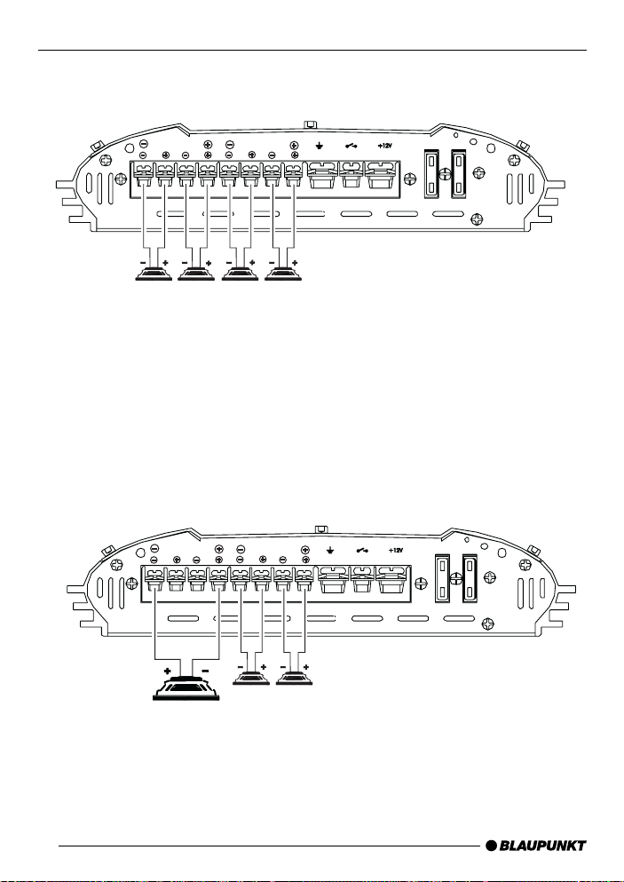
BGA 450
Fig. 3
4 Kanal / Channel Mode
(Quadro-Mode)
Fig. 4
REAR
BRIDGE MODE
CH4
CH3
min. 2 Ohm x4
REAR
BRIDGE MODE
CH4
CH3
FRONT
BRIDGE MODE
CH2
FRONT
BRIDGE MODE
CH2
CH1
REMOTE
GROUND
CH1
GROUND
REMOTE
SUPPLY
SUPPLY
FUSE
FUSE
FUSE
FUSE
3 Kanal / Channel Mode
36
min. 4 Ohm min. 2 Ohm x2
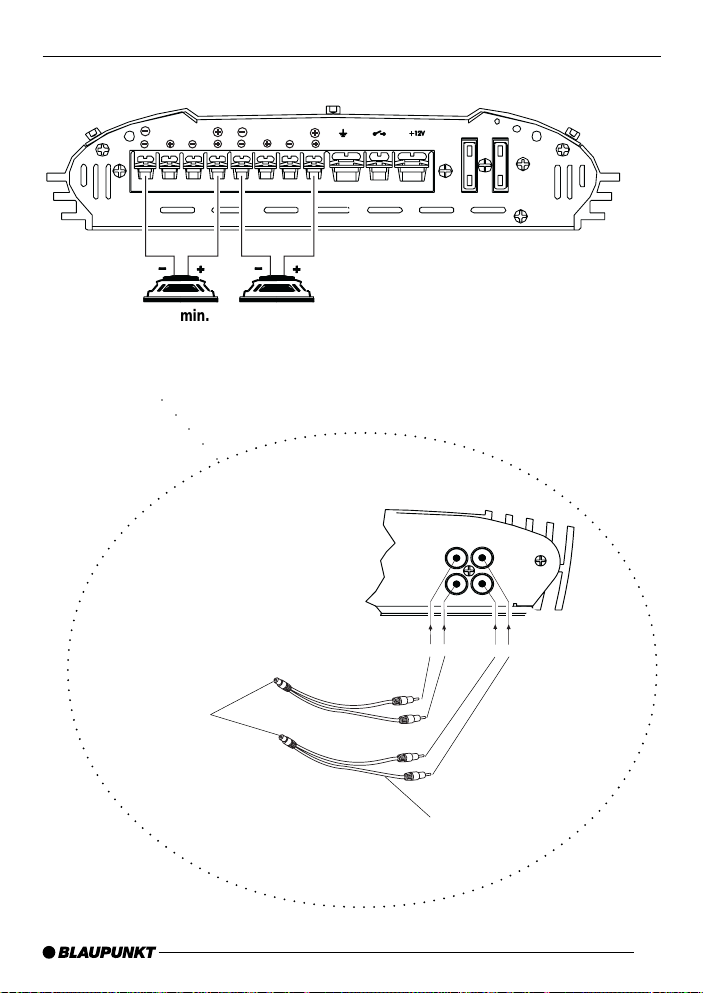
Fig. 5
BGA 450
REAR
BRIDGE MODE
CH4
CH3
min. 4 Ohm x2
2 Kanal / Channel Mode
(Stereo-Bridged Mode)
○ ○○○○
links / left
FRONT
BRIDGE MODE
CH2
CH1
GROUND
REMOTE
SUPPLY
CH 4
REAR
CH 3
Input
FUSE
LINE-IN
Input
CH 2
FRONT
CH 1
FUSE
REAR INPUT
rechts / right
2x Cinch-Y-Adapter
7 607 602 093
37

BGA 450
Änderungen vorbehalten!
This information is subject to change without notice!
Sous réserve de modifications!
Modifiche riservate!
Wijzigingen voorbehouden!
Ändringar förbehålles!
Modificaciones reservadas!
Sob reserva de alterações!
38

Service-Nummern / Service numbers / Numéros du service après-vente
/ Numeri del servizio di assistenza / Servicenummers / Telefonnummer
för service / Números de servicio / Número de serviço
Country: Phone: Fax: WWW:
Germany (D) 0180-5000225 05121-49 4002 http://www.blaupunkt.com
Austria (A) 01-610 390 01-610 393 91
Belgium (B) 02-525 5454 02-525 5263
Denmark (DK) 44 898 360 44-898 644
Finland (FIN) 09-435 991 09-435 99236
France (F) 01-4010 7007 01-4010 7320
Great Britain (GB) 01-89583 8880 01-89583 8394
Greece (GR) 0800-550 6550 01-576 9473
Ireland (IRL) 01-4149400 01-4598830
Italy (I) 02-369 6331 02-369 6464
Luxembourg (L) 40 4078 40 2085
Netherland (NL) 023-565 6348 023-565 6331
Norway (N) 66-817 000 66-817 157
Portugal (P) 01-2185 00144 01-2185 11111
Spain (E) 902-120234 916-467952
Sweden (S) 08-7501500 08-7501810
Switzerland (CH) 01-8471644 01-8471650
Czech. Rep. (CZ) 02-6130 0441 02-6130 0514
Hungary (H) 01-333 9575 01-324 8756
Poland (PL) 0800-118922 022-8771260
Turkey (TR) 0212-3350677 0212-3460040
USA (USA) 800-2662528 708-6817188
Brasil
(Mercosur) (BR) +55-19 3745 2769 +55-19 3745 2773
Malaysia
(Asia Pacific) (MAL) +604-6382 474 +604-6413 640
Blaupunkt GmbH
12/03 CM/PSS 8 622 403 987
 Loading...