


Einbauanleitung |
D |
Fitting instructions |
GB |
Instructions de montage |
F |
Instrucciones de montaje |
E |
Istruzioni di montaggio |
I |
Monteringsanvisning |
S |
Inbouwinstrukties |
NL |
Instruções de montagem |
P |
|
|
3 D93 653 064 |
7 607 760 511 |
|
|
Amplifier
BMX 720
|
D |
Lautsprecheranschluß |
|
Die Lautsprecher werden entsprechend der Tabelle Einsatzund Schalt- |
|
Produktbeschreibung |
|
|
|
möglichkeiten angeschlossen. |
|
|
|
|
6-/5-/4-/3-Kanal-Amplifier mit Schaltnetzteil und integrierter 3 Wege- Achtung : Lautsprecherkabel nicht mit Masse verbinden. |
||
Frequenzweiche. |
|
|
Einbauanleitung
Der Amplifier BMX 720 eignet sich zum Anschluß an Autoradios mit
„PREAMP OUTPUT“ nach DIN 45 326 oder Cinch-Anschluß.
Für den Anschluß an Autoradios mit Lautsprecherausgang das Adapterkabel 7 607 873 000 (Lautsprecherstecker  DIN-Buchse) verwenden. Über die 8polige AUX OUT-Buchse können mehrere Amplifier zusammen geschaltet werden.
Sicherheitshinweise
Einbauund Anschlußvorschriften
Für die Dauer des Anschlusses und der Gerätemontage ist der Minuspol der Batterie abzuklemmen.
Der BMX 720 wird an einem geeigneten Montageort z. B. an der
Spritzwand, oder im Kofferraum montiert. Bei der Wahl des Montageortes auf ausreichende Wärmeableitung achten. Vor dem Bohren der Befestigungslöcher sicherstellen, daß keine verlegten Kabel oder Fahrzeugteile beschädigt werden, Fig. 3.
Alle Kabel sind zur Störsicherheit in genügendem Abstand von Kabelbäumen zu verlegen.
Nur Lautsprecher mit 4 Ω Impendanz verwenden. Max. Belastbarkeit (Musikleistung) beachten.
Lautsprecheranschlußkabel bis 16 mm2 verwenden. Lautsprecher nicht an Masse schließen, nur die bezeichneten Klemmen verwenden.
Zum Schutz der Fahrzeugbatterie sollte der Amplifier nicht mit hoher Leistung bei stehendem Motor betrieben werden.
Plus- /Minus Anschluß
Beide beiliegenden Pluskabel zur Batterie legen und über die mitgelieferten Sicherungshalter am Pluspol der Batterie anschließen. An scharfkantigen Löchern beiliegende Kabeldurchführungen verwenden. Verstärkerseitig die beiden Pluskabel an den Klemmen B+ anschließen. Fig. 1.
Beide beiliegenden Minuskabel an einen störfreien Massepunkt
(Karosserieschraube, Karosserieblech) sicher anschrauben (nicht am Minuspol der Batterie). Kontaktfläche des Massepunktes metallisch blank kratzen und mit Graphitfett einfetten. Verstärkerseitig die beiden
Massekabel an den Klemmen GND anschließen. Fig. 1.
Anschluß an das Autoradio
Autoradios mit DIN-Ausgang mit dem Anschlußkabel 7 607 863 001 (5m) oder 7 607 652 061 (1,3m) und Verlängerung 7 607 244 000 (4m) an der 8 poligen Buchse INPUT anschließen. Fig. 4.
Autoradios mit Cinch-Ausgang mit Anschlußkabel 7 607 886 093 (5m) an den Cinch Buchsen LF, RF, LR, RR anschließen. Bei Anschluß über die
Cinch Buchsen muß die Schaltleitung REM, +14V geschaltet, mit angeschlossen werden. Fig. 4.
AUX OUT
Mit dem Anschlußkabel 7 607 652 061 können weitere Amplifier an der AUX OUT Buchse angeschlossen werden.
Einstellung der Regler und Schalter Fig. 4
GAIN ADJ
Beim Anschluß von Blaupunkt-Autoradios ist der Regler auf 2 V einzustellen.
Der Einstellbereich des Gain Adjust-Reglers reicht von 0,3 V bis 2 V.
Bei Anschluß eines Autoradios anderer Hersteller ist die Eingangsempfindlichkeit entsprechend den Herstellerangaben anzupassen.
LEVEL 1+2, 3+4, 5+6
Mit den Reglern kann für die Kanalpaare 1+2, 3+4, und 5+6 die Lautstärke um ± 10 dB geregelt werden.
BASS BOOST
In Stellung ON, 10 dB Lautstärkeanhebung bei 45 Hz.
TWT, LP.MID.HP, MID.HP, SUB.LP
Die Regler sind nur im 3- oder 2- Wegbetrieb aktiv. Der Regler SUB.LP ist zusätzlich im Full + Sub Betrieb aktiv. Die Stellung der Schalter INPUT
SELECT und MODE SELECT entnehmen Sie der Tabelle Einsatzund
Schaltmöglichkeiten.
Technische Daten
Max. Power: |
|
6 x 120 W oder 3 x 240 W an 4 Ω |
Sinus-Leistung: |
|
6 x 65 W oder 3 x 120 W bei 0,1% |
|
|
Klirrfaktor (DIN 45500) |
Klirrfaktor: |
|
typ. 0,01 % bei 10 W, 1 kHz, 4 Ω |
Frequenzbereich: |
|
10 Hz - 90 kHz (-3 dB) |
3 Weg Frequenzweiche: |
Subwoofer: Low Pass: 40 Hz - 250 Hz |
|
|
|
Mid Range: High Pass: 50 Hz - 350 Hz |
|
|
Low Pass: 2,4 - 5 kHz |
|
|
Tweeter: High Pass: 2,4 - 5kHz |
S/R - Abstand: |
|
>102 dB(A) |
Kanaltrennung: |
|
>60 dB / 1 kHz |
Schutzschaltung gegen Kurzschluß und Übertemperatur |
||
Eingänge: |
|
DIN (8pol.) und 4 Cinch RCA vergoldet |
Ausgänge: |
AUX OUT (8pol DIN), 6 Lautsprecher 4 Ω vergoldet |
|
Abmessungen (B x H x T): |
450 x 45 x 270 mm |
|
Änderungen vorbehalten

Einsatzund Schaltmöglichkeiten:
Input |
Mode |
|
|
|
|
Lautsprecheranschluß |
|
|
|
Bemerkung |
|||
Select |
Select |
1 Channel 2 |
3 Channel 4 |
5 Channel 6 |
|
||||||||
|
|
|
|
|
|
|
|
|
|
|
|||
Mono |
Mode1 |
RF Full* |
RR Full* |
RR Full* |
Fullrange |
||||||||
|
|
|
|
|
|
|
|
|
|
|
|
||
|
Mode 2 |
LF Full* |
|
LR Full* |
LR Full* |
Fullrange |
|||||||
|
|
|
|
|
|
|
|
|
|
|
|
||
|
Mode 3 |
RF High* |
RF Mid* |
Sub* |
|
3- Weg |
|||||||
|
|
|
|
|
|
|
|
|
|
|
|
|
|
|
Mode 4 |
LF High* |
LF Mid* |
|
Sub* |
|
3- Weg |
||||||
|
|
|
|
|
|
|
|
|
|
|
|
|
|
Stereo |
Mode 1 |
RF Full* |
LF Full* |
|
Sub* |
|
Full + Sub |
||||||
|
|
|
|
|
|
|
|
|
|
|
|
|
|
|
Mode 2 |
RF Full** |
|
|
LF Full** |
Sub* |
|
Sub* |
|
Full + Sub |
|||
|
|
|
|
|
|
|
|
|
|
|
|
|
|
|
Mode 3 |
RF High** |
|
|
LF High** |
RF Mid** |
|
|
LF Mid** |
Sub* |
|
3- Weg |
|
|
|
|
|
|
|
|
|
|
|
|
|
||
|
Mode 4 |
RF High/Mid* |
LF High/Mid* |
Sub* |
|
2- Weg |
|||||||
|
|
|
|
|
|
|
|
|
|
|
|
||
Quattro |
Mode 1 |
RF Full** |
|
LF Full** |
RR Full* |
LR Full* |
Fullrange |
||||||
4- Kanal |
|
|
|
|
|
|
|
|
|
|
|
|
|
Mode 2 |
RF Full* |
LF Full* |
|
RR Full** |
|
LR Full** |
Fullrange |
||||||
|
|
|
|||||||||||
|
|
|
|
|
|
|
|
|
|
|
|
||
|
Mode 3 |
RF Full** |
|
LF Full** |
RR Full** |
|
LR Full** |
Sub* |
|
Full + Sub |
|||
|
|
|
|
|
|
|
|
|
|
|
|
||
|
Mode 4 |
RF** |
|
LF** |
RR** |
|
LR** |
Sub* |
|
2- Weg |
|||
|
|
High/Mid |
|
High/Mid |
High/Mid |
|
High/Mid |
|
|
|
|
||
|
|
|
|
|
|
|
|
|
|
|
|
|
|
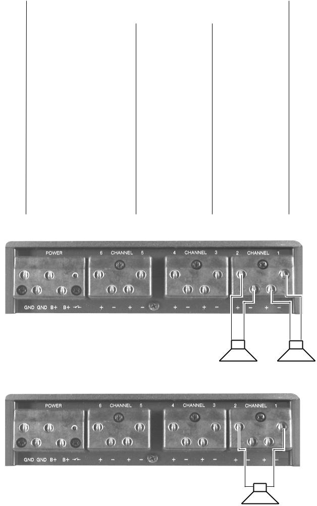
* Anschluß der Lautsprecher 2 x 120W, Fig. 1 oder 1 x 240W, Fig. 2. ( Beispiel Channel 1 + 2 ) ** Anschluß der Lautsprecher 2 x 120W, Fig. 1. ( Beispiel Channel 1 + 2 )
120 W |
120 W |
Fig. 1
240 W
Fig. 2
GB |
Loudspeaker connection |
|
The loudspeakers have to be connected in accordance with the table |
||
Product description |
||
“Ap plications and configurations” listed in the following. |
||
6-/5-/4-/3-channel amplifier with switch-mode power pack and integrated |
||
Attention: Never connect speaker leads to the vehicle ground! |
||
3-way crossover. |
||
|
Installation instructions
The BMX 720 amplifier suits to be connected to a car radio either equipped with a PREAMP OUTPUT in accordance with DIN 45326 or Cinch connectors.
For the connection to a unit fitted with speaker outputs use the adaptor cable 7 607 873 000 (speaker connector  DIN socket). Via the 8-pole AUX OUT socket it is possible to link several amplifiers.
Safety information
Mounting and connection instructions
Before connecting, disconnect the vehicle battery ground wire.
The BMX 720 is installed in an appropriate mounting location, for exam ple to the splash wall or in the boot. When choosing a location, take care for sufficient heat dissipation. Before drilling holes in the vehi cle bodywork, check what is on the other side to avoid damaging the wiring looms or other parts of the vehicle, fig. 3.
In order to avoid interference from adjacent wiring, all cables have to be routed at a sufficient distance to the wiring looms.
Use only loudspeakers with a 4 Ω impedance. Take into account the maximum power handling capacity (max. power).
To connect the speakers, use cable diameters of up to 16 mm2. Never connect speaker leads to the vehicle ground. Use only the terminals marked correspondingly.
To protect the vehicle battery, the amplifier should only be operated at moderate power values when then engine is switched off.
Positive/negative connection
Route both of the attached positive leads to the battery and connect to the positive battery pole via the fuse holder delivered with the system. Use the attached grommets where cables pass through holes in metal to avoid chafing. Connect the two positive wires to the B+ terminals of the amplifier, see fig. 1.
Securely screw the two negative leads to an interference-free ground spot of the vehicle (chassis screw or panel; do not connect to the nega tive battery pole). In the contact area, scrape off the paint and treat ground spot with graphite grease. Connect the two ground leads to the
GND terminals of the amplifier, see fig. 1.
Connection to the car radio
Car radios equipped with a DIN output are connected to the 8-pole INPUT socket via the connection cable 7 607 863 001 (5 m) or 7 607 652 061
(1.3 m) and extension 7 607 244 000 (4 m), see fig. 4.
Car radios equipped with a Cinch output are connected to the Cinch jack ets LF, RF, LR, RR via the connection cable 7 607 886 093 (5 m). In this case, the switching line REM +14 V has to be connected as well, see fig. 4.
AUX OUT
Use the connection cable 7 607 652 061 to hook up further amplifiers to the AUX OUT socket.
Control and switch settings, fig. 4
GAIN ADJ
Adjust the control to 2 V when connecting a Blaupunkt car radio. The gain adjust control range reaches from 0.3 V to 2 V. When connecting the set of another make, match the input sensitivity with the correspond ing manufacturer specifications.
LEVEL 1+2, 3+4, 5+6
Use these controls to adjust the volume of channel pairs 1+2, 3+4, and 5+6 by ± 10 dB.
BASS BOOST
When adjusted to ON, the volume is boosted by 10 dB at 45 Hz.
TWT, LP.MID.HP, MID.HP, SUB-LP
These controls are only active during 3- or 2-way operation. The control
SUB.LP is also active during full + sub operation. For the settings of the
INPUT SELECT and MODE SELECT switches, please refer to the table
“Applications and configurations”.
Technical data
Max. power: |
|
|
6 x 120 W or 3 x 240 W into 4 Ω |
RMS power: |
|
|
6 x 65 W or 3 x 120 W at 0.1 % distortion |
|
|
|
(DIN 45500) |
Distortion factor:t |
|
|
typ. 0.01 % at 10 W, 1 kHz, 4 Ω |
Frequency range: |
|
|
10 Hz - 90 kHz (-3 dB) |
3-way frequency crossover: |
Subwoofer: low-pass: 40 Hz - 250 Hz |
||
|
|
|
Mid-range: high-pass: 50 Hz - 350 Hz |
|
|
|
low-pass: 2.4 - 5 kHz |
|
|
|
Tweeter: high-pass: 2.4 - 5 kHz |
S/N distance: |
|
|
>102 dB (A) |
Channel separation: |
|
>60 dB / 1 kHz |
|
Circuit breaker for short circuit and overtemperature protection |
|||
Inputs: |
|
DIN (8-pole) and 4 Cinch RCA, gold-plated |
|
Outputs: |
AUX OUT (8-pole DIN), 6 speakers 4 Ω , gold-plated |
||
Dimensions (w/h/d): |
|
450 x 45 x 270 mm |
|
We reserve the right to make technical modifications!

Applications and configurations:
Input |
Mode |
|
|
|
|
Speaker Connector |
|
|
|
Remark |
|||
Select |
Select |
1 Channel 2 |
3 Channel 4 |
5 Channel 6 |
|
||||||||
|
|
|
|
|
|
|
|
|
|
|
|||
Mono |
Mode1 |
RF Full* |
RR Full* |
RR Full* |
Full range |
||||||||
|
|
|
|
|
|
|
|
|
|
|
|
||
|
Mode 2 |
LF Full* |
|
LR Full* |
LR Full* |
Full range |
|||||||
|
|
|
|
|
|
|
|
|
|
|
|
||
|
Mode 3 |
RF High* |
RF Mid* |
Sub* |
|
3-way |
|||||||
|
|
|
|
|
|
|
|
|
|
|
|
|
|
|
Mode 4 |
LF High* |
LF Mid* |
|
Sub* |
|
3-way |
||||||
|
|
|
|
|
|
|
|
|
|
|
|
|
|
Stereo |
Mode 1 |
RF Full* |
LF Full* |
|
Sub* |
|
Full + Sub |
||||||
|
|
|
|
|
|
|
|
|
|
|
|
|
|
|
Mode 2 |
RF Full** |
|
|
LF Full** |
Sub* |
|
Sub* |
|
Full + Sub |
|||
|
|
|
|
|
|
|
|
|
|
|
|
|
|
|
Mode 3 |
RF High** |
|
|
LF High** |
RF Mid** |
|
|
LF Mid** |
Sub* |
|
3-way |
|
|
|
|
|
|
|
|
|
|
|
|
|
||
|
Mode 4 |
RF High/Mid* |
LF High/Mid* |
Sub* |
|
2-way |
|||||||
|
|
|
|
|
|
|
|
|
|
|
|
||
Quattro |
Mode 1 |
RF Full** |
|
LF Full** |
RR Full* |
LR Full* |
Full range |
||||||
4-channel |
|
|
|
|
|
|
|
|
|
|
|
|
|
Mode 2 |
RF Full* |
LF Full* |
|
RR Full** |
|
LR Full** |
Full range |
||||||
|
|
|
|||||||||||
|
|
|
|
|
|
|
|
|
|
|
|
||
|
Mode 3 |
RF Full** |
|
LF Full** |
RR Full** |
|
LR Full** |
Sub* |
|
Full + Sub |
|||
|
|
|
|
|
|
|
|
|
|
|
|
||
|
Mode 4 |
RF** |
|
LF** |
RR** |
|
LR** |
Sub* |
|
2-way |
|||
|
|
High/Mid |
|
High/Mid |
High/Mid |
|
High/Mid |
|
|
|
|
||
|
|
|
|
|
|
|
|
|
|
|
|
|
|
* Speaker connection 2 x 120 W or 1 x 240 W, fig. 2 (example: channels 1+2).
** Speaker connection 2 x 120 W, fig. 1 (example: channels 1+2)
120 W |
120 W |
Fig. 1
240 W
Fig. 2
F
Description de produit
Amplificateur à 6/5/4/3 canaux avec réseau combinatoire et séparateur de fréquences intégré à 3 voies.
Instructions de montage
L’amplificateur BMX 720 est approprié pour la connexion aux autoradios pourvus de „PREAMP OUTPUT“ selon DIN 45 326 ou prise Cinch. Utiliser le câble adaptateur 7 607 873 000 (prise de haut-parleur  prise
prise
DIN) pour la connexion aux autoradios pourvus d’une sortie de hautparleur. Plusieurs amplificateurs peuvent être interconnectés par la prise AUX OUT à 8 pôles.
Instructions de sécurité
Instructions de montage et de branchement
Débrancher le pôle négatif de la batterie pendant les opérations de branchement et de montage de l’appareil.
Monter le BMX 720 à un endroit de montage approprié, p.ex. au tablier d’auvent ou dans le coffre. Veiller à une dissipation suffisante de la chaleur en choisissant l’endroit de montage.
Avant de perçer les trous de montage, veiller à ce que les câbles posés ne peuvent pas être endommagés, fig. 3.
Pour assurer l’antiparasitage, poser tous les câbles à une distance suffisante des formes de câbles.
N’utiliser que des haut-parleurs d’une impédance de 4 ohms. Respecter la puissance admissible (puissance musicale).
Utiliser des câbles de raccordement de 16 mm2 au maximum pour la connexion des haut-parleurs. Ne pas raccorder les haut-parleurs à la masse, utiliser seulement les bornes indiquées.
Pour protéger la batterie du véhicule, il est recommandé de ne pas utiliser l’amplificateur à une haute puissance et à l’arrêt du moteur.
Connexion positive/négative
Poser les deux câbles positifs inclus à la batterie et les connecter au pôle positif de la batterie par les porte-fusibles compris dans l’emballage. Utiliser les passe-câbles inclus pour les trous à bords vifs. Du côté amplificateur, connecter les deux câbles positifs aux bornes B+ de l’amplificateur, fig. 1.
Visser les deux câbles négatifs inclus à un point masse libre de parasites
(vis de carrosserie, tôle pour carrosserie, ne pas visser au pôle négatif de la batterie). Gratter la surface de contact du point masse et l’enduire de la graisse de graphite. Du côté amplificateur, connecter les deux câbles de mise à la masse aux bornes GND, fig. 1.
Connexion à l’autoradio
Connecter les autoradios à sortie DIN à la prise INPUT à 8 pôles en utilisant le câble de raccordement 7 607 863 001 de 5 m ou 7 607 652
061 de 1,3 m et le câble de rallonge 7 607 224 000 de 4 m, fig. 4.
Connecter les autoradios à sortie Cinch aux prises Cinch LF, RF, LR, RR en utilisant le câble de raccordement 7 607 886 093 de 5 m. En cas de connexion par les prises Cinch, la ligne de commutation REM, connecté
+14 V, doit également être connectée, fig. 4.
Connexion des haut-parleurs
La connexion des haut-parleurs est décrite dans le tableau Possibilités d’utilisation et de commutation.
Attention: Ne pas connecter le câble de haut-parleur à la masse.
AUX OUT
D’autres amplificateurs peuvent être connectés à la prise AUX OUT en utilisant le câble de raccordement 7 607 652 061.
Réglage des commutateurs et régulateurs, fig. 4.
GAIN ADJ
Régler le régulateur à 2 V en cas de connexion d’autoradios Blaupunkt.
La gamme de réglage du régulateur Gain Adjust est de 0,3 V à 2 V. En cas de connexion d’une autoradio d’un autre fabricant, la sensibilité d’entrée doit être adaptée suivant les indications du fabricant.
NIVEAUX 1+2, 3+4, 5+6
Les régulateurs permettent le réglage du volume sonore de +/- 10 dB pour les canaux 1+2, 3+4, 5+6.
BASS BOOST
En position ON, augmentation du volume sonore de 10 dB à 45 Hz.
TWT, LP.MID.HP, MID.HP. SUB.LP
Les régulateurs ne fonctionnent que dans le service à 3 ou 2 voies. Le réglage SUB.LP fonctionne supplémentairement dans le service Full
+Sub. La position des sélecteurs INPUT SELECT et MODE SELECT est indiquée dans le tableau Possibilités d’utilisation et de commutation.
Caractéristiques techniques
Puissance maximale: |
6 x 120 W ou 3 x 240 W sous 4 ohms |
Puissance sinusoïdale: |
6 x 65 W ou 3 x 120 W à un taux de |
|
distorsion de 0,1 % (DIN 45 500) |
Taux de distorsion: |
typ. 0,01 % à 10 W, 1 kHz, 4 ohms |
Gamme de fréquences: |
10 Hz - 90 kHz (-3 dB) |
Séparateur de fréquences |
|
à 3 voies: |
Subwoofer: Low Pass: 40 Hz - 250 Hz |
|
Mid Range: High Pass: 50 Hz - 350 Hz |
|
Low Pass: 2,4 - 5 kHz |
|
Tweeter: High Pass: 2,4 - 5kHz |
Rapport signal/bruit: |
>102 dB (A) |
Séparation des canaux: |
>60 dB / 1 kHz |
Circuit protecteur évitant les court-circuits et une élevation de la température.
Entrées: |
|
DIN (8 pôles) et 4 Cinch RCA dorées |
Sorties: |
AUX OUT (8 pôles DIN), 6 haut-parleurs, 4 ohms dorées |
|
Dimensions (L x H x P): |
450 x 45 x 270 mm |
|
Sous réserve de modifications!
Possibilités d’utilisation et de commutation:
Input |
Mode |
|
|
|
|
Connexion du haut-parleur |
|
Remarque |
|||||
Select |
Select |
1 Channel 2 |
3 Channel 4 |
5 Channel 6 |
|
||||||||
|
|
|
|
|
|
|
|
|
|
|
|||
Mono |
Mode1 |
RF Full* |
RR Full* |
RR Full* |
Fullrange |
||||||||
|
|
|
|
|
|
|
|
|
|
|
|
||
|
Mode 2 |
LF Full* |
|
LR Full* |
LR Full* |
Fullrange |
|||||||
|
|
|
|
|
|
|
|
|
|
|
|
||
|
Mode 3 |
RF High* |
RF Mid* |
Sub* |
|
3 voies |
|||||||
|
|
|
|
|
|
|
|
|
|
|
|
|
|
|
Mode 4 |
LF High* |
LF Mid* |
|
Sub* |
|
3 voies |
||||||
|
|
|
|
|
|
|
|
|
|
|
|
|
|
Stéréo |
Mode 1 |
RF Full* |
LF Full* |
|
Sub* |
|
Full + Sub |
||||||
|
|
|
|
|
|
|
|
|
|
|
|
|
|
|
Mode 2 |
RF Full** |
|
|
LF Full** |
Sub* |
|
Sub* |
|
Full + Sub |
|||
|
|
|
|
|
|
|
|
|
|
|
|
|
|
|
Mode 3 |
RF High** |
|
|
LF High** |
RF Mid** |
|
|
LF Mid** |
Sub* |
|
3 voies |
|
|
|
|
|
|
|
|
|
|
|
|
|
||
|
Mode 4 |
RF High/Mid* |
LF High/Mid* |
Sub* |
|
2 voies |
|||||||
|
|
|
|
|
|
|
|
|
|
|
|
||
Quattro |
Mode 1 |
RF Full** |
|
LF Full** |
RR Full* |
LR Full* |
Fullrange |
||||||
4 canaux |
|
|
|
|
|
|
|
|
|
|
|
|
|
Mode 2 |
RF Full* |
LF Full* |
|
RR Full** |
|
LR Full** |
Fullrange |
||||||
|
|
|
|||||||||||
|
|
|
|
|
|
|
|
|
|
|
|
||
|
Mode 3 |
RF Full** |
|
LF Full** |
RR Full** |
|
LR Full** |
Sub* |
|
Full + Sub |
|||
|
|
|
|
|
|
|
|
|
|
|
|
||
|
Mode 4 |
RF** |
|
LF** |
RR** |
|
LR** |
Sub* |
|
2 voies |
|||
|
|
High/Mid |
|
High/Mid |
High/Mid |
|
High/Mid |
|
|
|
|
||
|
|
|
|
|
|
|
|
|
|
|
|
|
|
* Connexion des haut-parleurs de 2 x 120 W ou 1 x 240 W, fig. 2 (exemple Channel 1+2)
** Connexion des haut-parleurs de 2 x 120 W, fig. 1 (exemple Channel 1+2)
120 W |
120 W |
Fig. 1
240 W
Fig. 2
 Loading...