


 Loading...
EB000000
YP250
SERVICE MANUAL1996 by Yamaha Motor Co., Ltd.
1st Edition, January 1996
All rights reserved. Any reprinting or unauthorized use without the written permission of Yamaha Motor Co., Ltd. is expressly prohibited.

EB001000
NOTICE
This manual was produced by the Yamaha Motor Company primarily for use by Yamaha dealers and their qualified mechanics. It is not possible to include all the knowledge of a mechanic in one manual, so it is assumed that anyone who uses this book to perform maintenance and repairs on Yamaha scooter has a basic understanding of the mechanical ideas and the procedures of scooter repair. Repairs attempted by anyone without this knowledge are likely to render the scooter unsafe and unfit for use.
Yamaha Motor Company, Ltd. is continually striving to improve all its models. Modifications and significant changes in specifications or procedures will be forwarded to all authorized Yamaha dealers and will appear in future editions of this manual where applicable.
NOTE:
Designs and specifications are subject to change without notice.
IMPORTANT INFORMATION
Particularly important information is distinguished in this manual by the following notations.
|
The Safety Alert Symbol means ATTENTION! BECOME ALERT! YOUR |
|||
|
SAFETY IS INVOLVED! |
|||
|
Failure to follow WARNING instructions could result in severe injury or death to |
|||
|
|
|
|
|
|
the scooter operator, a bystander or a person inspecting or repairing the scoot- |
|||
|
er. |
|||
|
A CAUTION indicates special precautions that must be taken to avoid damage |
|||
CAUTION: |
||||
|
to the scooter. |
|||
NOTE: |
||||
A NOTE provides key information to make procedures easier or clearer. |
||||

YP002000
HOW TO USE THIS MANUAL
MANUAL ORGANIZATION
This manual consists of chapters for the main categories of subjects. (See ªIllustrated symbolsº)
1st title 1 : This is the title of the chapter with its symbol on the upper right corner of each page.
2nd title 2 : This title indicates the section of the chapter and only appears on the first page of each section. It is located in the upper left corner of the page.
3rd title 3 : This title indicates a sub-section that is followed by step-by-step procedures accompanied by corresponding illustrations.
EXPLODED DIAGRAMS
To heps identify parts and clarify procedure steps, there are exploded diagrams at start of each removal and disassembly section.
1.An easy-to-see exploded diagram 4 is provided for disassembly and assembly jobs.
2.Numbers 5 are given in the order of jobs in the exploded diagram. A number that is enclosed by a circle indicates a disassembly step.
3.An explanation of jobs and notes is presented in an easy-to-read way by the use of symbol marks 6 . The meanings of the symbol marks are given on the next page.
4.A job instruction chart 7 accompanies the exploded diagram, providing the order of jobs, names of parts, notes in jobs, etc.
5.For jobs requiring more information, the step-by-step format supplements 8 are given in addition to the exploded diagram and the job instruction chart.
2 |
1 |
4 |
3 |
5 |
8 |
|
6
6
7

1 |
2 |
3 |
4 |
5 |
6 |
7 |
8 |
9 |
10 |
11 |
12 |
13 |
14 |
15 |
16 |
17 |
18 |
19 |
20 |
21 |
22 |
23 |
24 |
25 |
EB003000
ILLUSTRATED SYMBOLS
Illustrated symbols 1 to 9 are designed as thumb tabs to indicate the chapter's number and content.
1General information
2Specifications
3Periodic inspection and adjustment
4Engine
5Cooling system
6Carburetion
7Chassis
8Electrical
9Troubleshooting
Illustrated symbols 10 to 17 are used to identify the specifications appearing in the text.
10Possible to maintain with engine mounted
11Filling fluid
12Lubricant
13Special tool
14Tightening
15Wear limit, clearance
16Engine speed
17Ω, V, A
Illustrated symbols 18 to 23 in the exploded diagrams indicate the types of lubricants and lubrication points.
18Apply engine oil
19Apply gear oil
20Apply molybdenum disulfide oil
21Apply wheel bearing grease
22Apply lightweight lithium-soap base grease
23Apply molybdenum disulfide grease
Illustrated symbols 24 to 25 in the exploded diagrams indicate the where to apply locking agent 24 and when to install new parts 25 .
24 Apply locking agent (LOCTITE )
25 Use new one

INDEX
GENERAL INFORMATION |
|
|
|
GEN |
1 |
||
|
INFO |
||
|
|
|
|
SPECIFICATIONS |
|
|
|
SPEC |
2 |
||
|
|||
|
|
|
|
PERIODIC INSPECTION AND |
|
|
|
INSP |
3 |
||
ADJUSTMENT |
|||
ADJ |
|||
|
|
|
|
ENGINE OVERHAUL |
|
|
|
ENG |
4 |
||
|
|||
|
|
|
|
COOLING SYSTEM |
|
|
|
COOL |
5 |
||
|
|||
|
|
|
|
CARBURETION |
|
|
|
CARB |
6 |
||
|
|||
|
|
|
|
CHASSIS |
|
|
|
CHAS |
7 |
||
|
|||
|
|
|
|
ELECTRICAL |
|
|
|
ELEC |
8 |
||
|
|||
|
|
|
|
TROUBLESHOOTING |
|
|
|
TRBL |
9 |
||
|
SHTG |

CHAPTER 1
GENERAL INFORMATION
SCOOTER IDENTIFICATION . . . . . . . . . . . . . . . . . . . . . . . . . . . . . . . . . . . . 1-1 VEHICLE IDENTIFICATION NUMBER (for E) . . . . . . . . . . . . . . . . . . . 1-1 FRAME SERIAL NUMBER . . . . . . . . . . . . . . . . . . . . . . . . . . . . . . . . . . . 1-1 ENGINE SERIAL NUMBER . . . . . . . . . . . . . . . . . . . . . . . . . . . . . . . . . . 1-1 MODEL LABEL . . . . . . . . . . . . . . . . . . . . . . . . . . . . . . . . . . . . . . . . . . . . . 1-1
FEATURES . . . . . . . . . . . . . . . . . . . . . . . . . . . . . . . . . . . . . . . . . . . . . . . . . . . 1-2 OIL INDICATOR LIGHT . . . . . . . . . . . . . . . . . . . . . . . . . . . . . . . . . . . . . . 1-2 AUTO CHOKE SYSTEM . . . . . . . . . . . . . . . . . . . . . . . . . . . . . . . . . . . . . 1-3 IGNITION CIRCUIT CUT-OFF SYSTEM . . . . . . . . . . . . . . . . . . . . . . . 1-3 IMPORTANT INFORMATION . . . . . . . . . . . . . . . . . . . . . . . . . . . . . . . . . . . . 1-4 PREPARATION FOR REMOVAL PROCEDURES . . . . . . . . . . . . . . . 1-4 REPLACEMENT PARTS . . . . . . . . . . . . . . . . . . . . . . . . . . . . . . . . . . . . . 1-4 GASKETS, OIL SEALS, AND O-RINGS . . . . . . . . . . . . . . . . . . . . . . . . 1-4 LOCK WASHERS/PLATES AND COTTER PINS . . . . . . . . . . . . . . . . 1-5 BEARINGS AND OIL SEALS . . . . . . . . . . . . . . . . . . . . . . . . . . . . . . . . . 1-5 CIRCLIPS . . . . . . . . . . . . . . . . . . . . . . . . . . . . . . . . . . . . . . . . . . . . . . . . . . 1-5 CHECKING OF CONNECTIONS . . . . . . . . . . . . . . . . . . . . . . . . . . . . . . 1-6 HOW TO USE THE CONVERSION TABLE . . . . . . . . . . . . . . . . . . . . . 1-7 SPECIAL TOOLS . . . . . . . . . . . . . . . . . . . . . . . . . . . . . . . . . . . . . . . . . . . . . . 1-8

GEN
SCOOTER IDENTIFICATION INFO
YP100000
GENERAL INFORMATION
SCOOTER IDENTIFICATION
YP100010
VEHICLE IDENTIFICATION NUMBER (for E)
The vehicle identification number 1 is stamped into the right side of the frame.
NOTE:
The vehicle identification number is used to identify your scooter and may be used to register your scooter with the licensing authority in your country.
YP100020
FRAME SERIAL NUMBER (except for E)
The frame serial number 1 is stamped into the right side of the frame.
EB100030
ENGINE SERIAL NUMBER
The engine serial number 1 is stamped into the crankcase.
NOTE:
Designs and specifications are subject to change without notice.
MODEL LABEL
The model label 1 is affixed under the seat. This information will be needed to order spare parts.
1-1
GEN
FEATURES INFO
FEATURES
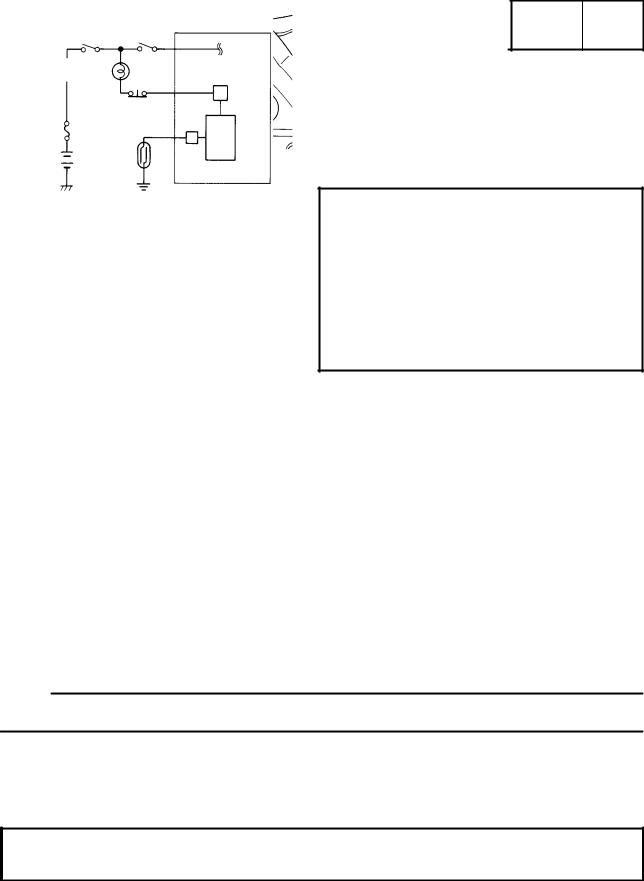
OIL INDICATOR LIGHT
Function
Pulses (travel distance signals) from the speedometer are counted and cause the oil indicator light to come on at 1,000 km for the first time and thereafter every 3,000 km. In this way, this light indicates the time for oil change.
Circuit diagram
Engine stop
Main switch Ignitor unit switch
Oil indicator light
|
Reset button |
|
|
Fuse |
|
|
|
Battery |
Meter |
|
Oil indicator light |
C.P.U |
Reset button |
||
|
|
|
Resetting procedure
Travel distance can be reset if the reset button is held down for 2 to 5 seconds with the main switch ªONº.
1)If the ªresettingº is done while the oil light is on, the oil indicator light goes off for resetting confirmation.
2)If the ªresettingº is done while the oil light is off, the oil indicator light comes on for 1.4 seconds for resetting confirmation.
Failure diagnosis
1)Checking oil indicator light for breakage
This oil indicator light is kept on for 1.4 seconds immediately after the main switch is turned on, thereby checking the bulb for breakage.
2)In case of meter pulse failure
If travel distance signals are not detected during running, the oil indicator light flashes and gives a warning of meter signal failure.
NOTE:
This circuit may be activated if the engine is accelerated without load with the mainestand put up.
Battery tending to discharge.
If the starting motor is run with the battery tending to discharge, the oil indicator light may come on (for 1.4 seconds), but this is noting abnormal.
In this case recharge or replace battery.
This light comes on if battery charging becomes poor, thereby causing the engine to run as low as about 200 rpm against 600 rpm or so,
1-2

FEATURES
AUTO-CHOKE SYSTEM
GEN INFO
This system is the parallel connection of the ignitor unit circuit and the thermo switch as shown, detecting the engine temperature, and facilitates the restarting with the warm engine.
Circuit diagram |
Igniter unit |
|
Main switch |
|
|
Fuse |
Thermo |
|
|
|
|
|
|
|
switch |
|
|
Ignition |
|
||
|
|
|
|
|
|
|||
|
|
|
|
|
C.P.U |
|
||
|
Battery |
|
|
|
|
|
|
|
|
|
|
Auto-choke |
|
|
|
|
|
Auto-choke operation |
|
|
|
|
|
|
||
|
|
|
|
|
|
|
|
|
Engine condition |
|
Start with the |
Crank with the |
|
Crank with the |
|
Restart with the |
|
|
cold engine |
cold engine |
|
warm engine |
|
warm engine |
||
|
|
|
|
|||||
|
|
|
|
|
|
|
|
|
Thermo switch |
|
OFF |
|
OFF |
|
ON |
|
ON |
|
|
|
|
|
|
|
|
|
Ignitor unit circuit |
|
OFF |
|
ON |
|
ON |
|
OFF |
|
|
|
|
|
|
|
|
|
Auto-choke |
|
Activates |
|
Activates |
|
Not activate |
|
Not activate |
|
|
|
|
|
|
|
|
|
IGNITION CIRCUIT CUT-OFF SYSTEM
A sidestand circuit is added to the existing electric starting circuit, thereby controlling the starter motor operation and the ignition system of the igniter unit.
Circuit diagram
|
Main switch |
|
Engine stop switch |
|
|
|
||
|
|
|
|
Brake |
|
|
|
|
|
|
|
|
switch |
|
|
Ignitor unit |
|
Fuse |
|
|
|
|
||||
|
|
|
|
|
|
|||
|
Starter relay |
|
|
Relay |
|
|
|
|
|
|
|
|
|
|
|
|
|
Battery |
|
Starter |
Start |
Brake light |
Sidestand |
|||
|
|
|||||||
|
|
switch |
switch |
|||||
|
|
motor |
|
|||||
|
|
|
|
|
|
|
||
Operating mode |
|
|
|
|
|
|
|
|
|
|
|
|
|
|
|||
Sidestand switch |
|
Operation of brake |
Operation of starter |
|
Operation of igniter |
|||
|
|
light |
|
motor |
|
|
unit control |
|
|
|
|
|
|
|
|||
|
|
|
|
|
|
|
|
|
OFF |
|
|
ON |
|
Not operated |
|
|
Misfire |
(Sidestand in use) |
|
|
OFF |
|
Not operated |
|
|
Misfire |
|
|
|
|
|
|
|
|
|
ON |
|
|
ON |
|
Operated |
|
|
Ignited |
(Sidestand folded in) |
|
|
OFF |
|
Not operated |
|
|
Ignited (ridden) |
|
|
|
|
|
|
|
|
|
1-3

GEN
IMPORTANT INFORMATION INFO
EB101000
IMPORTANT INFORMATION
PREPARATION FOR REMOVAL PROCEDURES
1.Remove all dirt, mud, dust and foreign material before removal and disassembly.
2.Use proper tools and cleaning equipment.
3.Refer to the ªSPECIAL TOOLSº section.
4.When disassembling the machine, always keep mated parts together. This includes gears, cylinders, pistons and other parts that have been ªmatedº through normal wear. Mated parts must always be reused or replaced as an assembly.
5.During machine disassembly, clean all parts and place them in trays in the order of disassembly. This will speed up assembly and allow for the correct installation of all parts.
6.Keep all parts away from any source of fire.
EB101010
REPLACEMENT PARTS
1.Use only genuine Yamaha parts for all replacements. Use oil and grease recommended by Yamaha for all lubrication jobs. Other brands may be similar in function and appearance, but inferior in quality.
EB101020
GASKETS, OIL SEALS AND O-RINGS
1.Replace all gaskets, seals and O-rings when overhauling the engine. All gasket surfaces, oil seal lips and O-rings must be cleaned.
2.Properly oil all mating parts and bearings during reassembly. Apply grease to the oil seal lips.
1-4
GEN
IMPORTANT INFORMATION INFO
OR
EB101030
LOCK WASHERS/PLATES AND COTTER PINS
1.Replace all lock washers/plates and cotter pins after removal. Bend lock tabs along the bolt or nut flats after the bolt or nut has been tightened to specification.
EB101040
BEARINGS AND OIL SEALS
Install bearings and oil seals so that the manufacturer's marks or numbers are visible. When installing oil seals, apply a light coating of lightweight lithium base grease to the seal lips. Oil bearings liberally when installing, if appropriate.
1 Oil seal
CAUTION:
Do not use compressed air to spin the bearings dry. This will damage the bearing surfaces.
1 Bearing
EB101050
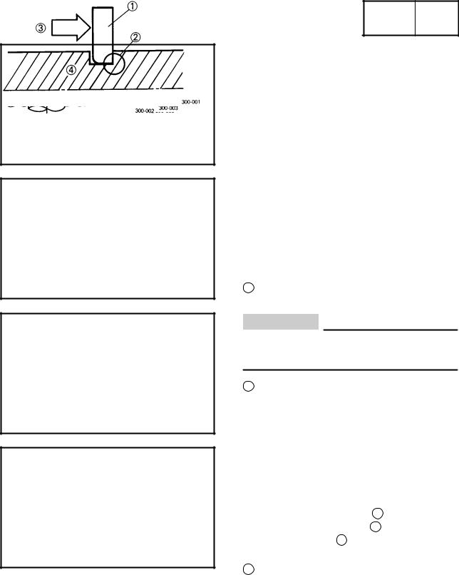
CIRCLIPS
1.Check all circlips carefully before reassembly. Always replace piston pin clips after one use. Replace distorted circlips. When installing a circlip 1 , make sure that the sharp-edged corner 2 is positioned opposite the thrust 3 it receives. See sectional view.
4 Shaft
1-5

IMPORTANT INFORMATION
EB801000
GEN INFO
CHECKING OF CONNECTIONS
Dealing with stains, rust, moisture, etc. on the connector.
1.Disconnect: S Connector
2.Dry each terminal with an air blower.
3.Connect and disconnect the connector two or three.
4.Pull the lead to check that it will not come off.
5.If the terminal comes off, bend up the pin 1 and reinsert the terminal into the connector.
6.Connect:
S Connector
NOTE:
The two connectors ªclickº together.
7. Check for continuity with a tester.
NOTE:
DIf there is no continuity, clean the terminals.
DBe sure to perform the steps 1 to 7 listed above when checking the wireharness.
DFor a field remedy, use a contact revitalizer available on the market.
DUse the tester on the connector as shown.
1-6
HOW TO USE THE CONVERSION TABLE
EB201000
GEN INFO
HOW TO USE THE CONVERSION TABLE
All specification data in this manual are listed in SI and METRIC UNITS.
Use this table to convert METRIC unit data to IMPERIAL unit data. |
|
||||||||
Ex. |
|
|
|
|
|
|
|
|
|
METRIC |
|
MULTIPLIER |
IMP |
|
|
|
|
||
**mm |
|
0.03937 |
= |
** in |
|
|
|
|
|
2 mm |
|
0.03937 |
= |
0.08 in |
|
||||
CONVERSION TABLE |
|
|
|
|
|
|
|||
|
|
|
|
|
|
|
|
|
|
|
|
|
|
|
|
METRIC TO IMP |
|
||
|
|
|
|
|
|
|
|
|
|
|
|
|
|
Known |
|
Multiplier |
|
Result |
|
|
|
|
|
|
|
|
|
|
|
|
|
|
|
m kg |
|
|
7.233 |
|
ft lb |
Torque |
|
|
|
m kg |
|
|
86.794 |
|
in lb |
|
|
|
cm kg |
|
|
0.0723 |
|
ft lb |
|
|
|
|
|
|
|
|
|||
|
|
|
|
cm kg |
|
|
0.8679 |
|
in lb |
Weight |
|
|
|
kg |
|
|
2.205 |
|
lb |
|
|
|
g |
|
|
0.03527 |
|
oz |
|
|
|
|
|
|
|
|
|||
|
|
|
|
|
|
|
|
|
|
|
|
|
|
km/hr |
|
|
0.6214 |
|
mph |
|
|
|
|
km |
|
|
0.6214 |
|
mi |
Distance |
|
|
|
m |
|
|
3.281 |
|
ft |
|
|
|
m |
|
|
1.094 |
|
yd |
|
|
|
|
|
|
|
|
|||
|
|
|
|
cm |
|
|
0.3937 |
|
in |
|
|
|
|
mm |
|
|
0.03937 |
|
in |
|
|
|
|
|
|
|
|
|
|
|
|
|
|
cc (cm3) |
|
0.03527 |
|
oz (IMP liq.) |
|
Volume/ |
|
|
|
cc (cm3) |
|
0.06102 |
|
cu in |
|
Capacity |
|
|
|
lit (liter) |
|
0.8799 |
|
qt (IMP liq.) |
|
|
|
|
|
lit (liter) |
|
0.2199 |
|
gal (IMP liq.) |
|
|
|
|
|
|
|
|
|
|
|
Miscella- |
|
|
|
kg/mm |
|
|
55.997 |
|
lb/in |
|
|
|
kg/cm2 |
|
14.2234 |
|
psi (lb/in2) |
||
neous |
|
|
|
|
|
||||
|
|
|
Centigrade |
|
9/5(_C) + 32 |
|
Fahrenheit (_F) |
||
|
|
|
|
|
|
||||
1-7
SPECIAL TOOLS
EB102000
GEN INFO
SPECIAL TOOLS
The following special tools are necessary for complete and accurate tune-up and assembly.
Use only the appropriate special tools; this will help prevent damage caused by the use of inappropriate tools or improvised techniques.
When placing an order, refer to the list provided below to avoid any mistakes.
Tool No. |
Tool name/Usage |
Illustration |
|
|
|
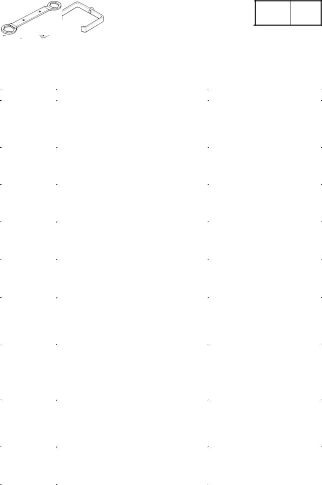
90890-01084 |
Weight |
|
-01085 |
Rocker arm shaft puller bolt |
|
|
These tools are used when removing |
|
|
or installing the rocker arm shafts. |
|
|
|
|
90890-01235 |
Rotor holding tool |
|
|
This tool is used to remove the |
|
|
flywheel magneto. |
|
|
|
|
90890-01268 |
Ringnut wrench |
|
|
This tool is used to loosen and tighten |
|
|
the exhaust and steering ringnut. |
|
|
|
|
90890-01311 |
Valve adjusting tool |
|
|
This tool is necessary for adjusting |
|
|
valve clearance. |
|
|
|
|
90890-01312 |
Fuel level gauge |
|
|
This gauge is used to measure the fuel |
|
|
level in the float chamber. |
|
|
|
|
90890-01325 |
Radiator cap tester |
|
-01352 |
Adaptor |
|
|
These tools are used for checking the |
|
|
cooling system. |
|
|
|
|
90890-01326 |
T-handle |
|
-04084 |
Damper rod holder |
|
|
These tool are used for holding the |
|
|
damper rod holder when removing or |
|
|
installing the damper rod holder. |
|
|
|
|
90890-01337 |
Clutch spring compressor |
|
-01464 |
Clutch spring holder arm |
|
|
These tools are used for removing the |
|
|
nut with holding the compression spring. |
|
|
|
|
90890-01348 |
Locknut wrench |
|
|
This tool is used when removing or |
|
|
installing the secondary sheave nut. |
|
|
|
|
1-8

|
SPECIAL TOOLS |
|
|
GEN |
|
|
|
|
|
INFO |
|
||
|
|
|
|
|||
Tool No. |
Tool name/Usage |
|
Illustration |
|||
|
|
|
|
|
|
|
90890-01362 |
Flywheel puller |
|
|
|
|
|
|
This tool is used for removing the |
|
|
|
|
|
|
rotor. |
|
|
|
|
|
|
|
|
|
|
|
|
90890-01367 |
Fork seal driver weight |
|
|
|
|
|
-01368 |
Fork seal driver attachment (ù33) |
|
|
|
|
|
|
This tool is used when installing the |
|
|
|
|
|
|
fork seal. |
|
|
|
|
|
|
|
|
|
|
|
|
90890-01384 |
Oil seal guide |
|
|
|
|
|
|
This tool is used for protecting the oil |
|
|
|
|
|
|
seal lip when installing the secondary |
|
|
|
|
|
|
sliding sheave. |
|
|
|
|
|
|
|
|
|
|
|
|
90890-01403 |
Ring nut wrench |
|
|
|
|
|
|
This tool is used to loosen and tighten |
|
|
|
|
|
|
the steering ring nut. |
|
|
|
|
|
|
|
|
|
|
|
|
90890-01701 |
Sheave holder |
|
|
|
|
|
|
This tool is used for holding the |
|
|
|
|
|
|
secondary sheave. |
|
|
|
|
|
|
|
|
|
|
|
|
90890-01996 |
Cylinder cup installer set |
|
|
|
|
|
|
This tool is used for installing the |
|
|
|
|
|
|
cylinder cup to the master cylinder |
|
|
|
|
|
|
piston. |
|
|
|
|
|
|
|
|
|
|
|
|
90890-03079 |
Thickness gauge |
|
|
|
|
|
|
This tool is used to measure the valve |
|
|
|
|
|
|
clearance. |
|
|
|
|
|
|
|
|
|
|
|
|
90890-03081 |
Compression gauge |
|
|
|
|
|
|
These tools are used to measure the |
|
|
|
|
|
|
engine compression. |
|
|
|
|
|
|
|
|
|
|
|
|
90890-03112 |
Pocket tester |
|
|
|
|
|
|
These instruments are invaluable for |
|
|
|
|
|
|
checking the electrical system. |
|
|
|
|
|
|
|
|
|
|
|
|
90890-03113 |
Engine tachometer |
|
|
|
|
|
|
This tool is needed for detecting |
|
|
|
|
|
|
engine rpm. |
|
|
|
|
|
|
|
|
|
|
|
|
1-9

|
SPECIAL TOOLS |
|
|
GEN |
|
|
|
|
|
INFO |
|
||
|
|
|
|
|||
Tool No. |
Tool name/Usage |
|
Illustration |
|||
|
|
|
|
|
|
|
90890-03141 |
Timing light |
|
|
|
|
|
|
This tool is needed for detecting |
|
|
|
|
|
|
ignition timing. |
|
|
|
|
|
|
|
|
|
|
|
|
90890-04101 |
Valve lapper |
|
|
|
|
|
|
This tool is used for removing and |
|
|
|
|
|
|
installing the lifter and for lapping the |
|
|
|
|
|
|
valve. |
|
|
|
|
|
|
|
|
|
|
|
|
90890-04019 |
Valve spring compressor |
|
|
|
|
|
-04108 |
Attachment |
|
|
|
|
|
|
These tools are used when removing |
|
|
|
|
|
|
or installing the valve and the valve |
|
|
|
|
|
|
spring. |
|
|
|
|
|
|
|
|
|
|
|
|
90890-04058 |
Middle shaft bearing driver |
|
|
|
|
|
-04078 |
Mechanical seal installer |
|
|
|
|
|
|
These tools are used for installing |
|
|
|
|
|
|
mechanical seal. |
|
|
|
|
|
|
|
|
|
|
|
|
90890-06754 |
Ignition checker |
|
|
|
|
|
|
This instrument is necessary for checking |
|
|
|
|
|
|
the ignition system components. |
|
|
|
|
|
|
|
|
|
|
|
|
90890-85505 |
Yamaha bond No. 1215 |
|
|
|
|
|
|
This sealant (bond) is used for crankcase |
|
|
|
|
|
|
mating surface, etc. |
|
|
|
|
|
|
|
|
|
|
|
|
1-10
CHAPTER 2.
SPECIFICATIONS
GENERAL SPECIFICATIONS . . . . . . . . . . . . . . . . . . . . . . . . . . . . . . . . . . . 2-1 MAINTENANCE SPECIFICATIONS . . . . . . . . . . . . . . . . . . . . . . . . . . . . . . 2-4 ENGINE . . . . . . . . . . . . . . . . . . . . . . . . . . . . . . . . . . . . . . . . . . . . . . . . . . . 2-4
CHASSIS . . . . . . . . . . . . . . . . . . . . . . . . . . . . . . . . . . . . . . . . . . . . . . . . . . 2-10 ELECTRICAL . . . . . . . . . . . . . . . . . . . . . . . . . . . . . . . . . . . . . . . . . . . . . . 2-14 GENERAL TORQUE SPECIFICATIONS . . . . . . . . . . . . . . . . . . . . . . . . . . 2-16
LUBRICATION POINTS AND GRADE OF LUBRICANT . . . . . . . . . . . . 2-17 ENGINE . . . . . . . . . . . . . . . . . . . . . . . . . . . . . . . . . . . . . . . . . . . . . . . . . . . 2-17 CHASSIS . . . . . . . . . . . . . . . . . . . . . . . . . . . . . . . . . . . . . . . . . . . . . . . . . . 2-18 CABLE ROUTING . . . . . . . . . . . . . . . . . . . . . . . . . . . . . . . . . . . . . . . . . . . . . 2-19


|
GENERAL SPECIFICATIONS |
SPEC |
|
||
|
|
|
|
|
|
|
SPECIFICATIONS |
||||
GENERAL SPECIFICATIONS |
|||||
|
|
|
|||
Model |
|
YP250 |
|||
|
|
|
|||
Model code: |
|
4UC 1 (except for CH, A) |
|||
|
|
4UD1 (for CH, A) |
|||
|
|
|
|
|
|
Dimensions: |
|
|
|
|
|
Overall length |
|
2,110 mm |
|||
Overall width |
|
750 mm |
|||
Overall height |
|
1,330 mm |
|||
Seat height |
|
700 mm |
|||
Wheelbase |
|
1,500 mm |
|||
Minimum ground clearance |
|
115 mm |
|||
Minimum turning radius |
|
2,600 mm |
|||
|
|
|
|
|
|
Basic weight: |
|
|
|
|
|
With oil and full fuel tank |
|
158 kg |
|||
|
|
|
|
|
|
Engine: |
|
|
|
|
|
Engine type |
|
Liquid-cooled 4-stroke, SOHC |
|||
Cylinder arrangement |
|
Forward-inclined single cylinder |
|||
Displacement |
|
0.249L (249 cm3) |
|||
Bore stroke |
|
69.0 66.8 mm |
|||
Compression ratio |
|
10 : 1 |
|
|
|
Compression pressure (STD) |
|
1,400 kPa (14 kg/cm2, 14 bar) at 500 r/min |
|||
Starting system |
|
Electric starter |
|||
Lubrication system: |
|
Wet sump |
|||
|
|
|
|
|
|
Oil type or grade: |
|
|
|
|
|
Engine oil |
|
|
|
|
|
|
|
API STANDERD: |
|||
|
|
SE or higher grade |
|||
Periodic oil change |
1.2 L |
Total amount |
1.4 L |
Transmission oil |
|
Total amount |
0.25 L |
|
|
Radiator capacity |
|
Total amount (including all routes) |
1.4 L |
|
|
Air filter: Carburetor side |
Wet type element |
Crankcase side |
Dry type element |
|
|
Fuel: |
|
Type |
Regular unleaded gasoline |
Fuel tank capacity |
11 L |
|
|
2-1

|
|
GENERAL SPECIFICATIONS |
|
SPEC |
|
|
|
|
|
|
|
|
|
|
|
|
|
|
|
|
|
Model |
|
YP250 |
|
|
|
|
|
|
|
|
|
|
Carburetor: |
|
|
|
|
|
|
Type/quantity |
|
|
Y28V-1A/1 |
|
|
|
Manufacturer |
|
|
TEIKEI |
|
|
|
|
|
|
|
|
|
|
Spark plug: |
|
|
|
|
|
|
Type |
|
|
DR8EA |
|
|
|
Manufacturer |
|
|
NGK |
|
|
|
Spark plug gap |
|
|
0.6 X 0.7 mm |
|
|
|
|
|
|
|
|
|
|
Clutch type: |
|
|
Dry, centrifugal automatic |
|
|
|
|
|
|
|
|
|
|
Transmission: |
|
|
|
|
|
|
Primary reduction system |
|
Helical gear |
|
|
|
|
Primary reduction ratio |
|
40/15 (2.666) |
|
|
|
|
Secondary reduction sytem |
|
Sper gear |
|
|
|
|
Secondary reduction ratio |
|
37/16 (2.312) |
|
|
|
|
Transmission type |
|
Single speed automatic (V-belt type) |
||||
Operation |
|
|
Centrifugal automatic type |
|
|
|
Single speed automatic |
|
2.20 X 0.88:1 |
|
|
|
|
|
|
|
|
|
|
|
Chassis: |
|
|
|
|
|
|
Frame type |
|
|
Steel tube underbone |
|
|
|
Caster angle |
|
|
28 |
|
|
|
Trail |
|
|
103 mm |
|
|
|
|
|
|
|
|
|
|
Tire: |
|
|
|
|
|
|
Type |
|
|
Tubeless |
|
|
|
Size |
front |
|
110/90-12 64J |
|
|
|
|
rear |
|
130/70-12 62L |
|
|
|
Manufacturer |
front |
|
IRC/CHENG SHIN |
|
|
|
|
rear |
|
IRC/CHENG SHIN |
|
|
|
Type |
front |
|
MB61/C922 |
|
|
|
|
rear |
|
MB61/C940 |
|
|
|
|
|
|
|
|
|
|
Tire pressure (cold tire): |
|
|
|
|
|
|
Maximum load-except motorcycle |
|
197 kg |
|
|
|
|
Loading condition A* |
|
0 X 90 kg |
|
|
|
|
|
front |
|
175 kPa (1.75 kg/cm2, 1.75 bar) |
|||
|
rear |
|
200 kPa (2.0 kg/cm2, 2.0 bar) |
|||
Loading condition B* |
|
90 X 205 kg |
|
|
|
|
|
front |
|
200 kPa (2.0 kg/cm2, 2.0 bar) |
|||
|
rear |
|
225 kPa (2.25 kg/cm2, 2.25 bar) |
|||
High-speed riding |
|
|
|
|
|
|
|
front |
|
200 kPa (2.0 kg/cm2, 2.0 bar) |
|||
|
rear |
|
250 kPa (2.5 kg/cm2, 2.5 bar) |
|||
*Load is the total weight of cargo, rider, passenger, and accessories.
2-2

|
|
GENERAL SPECIFICATIONS |
|
SPEC |
|
||
|
|
|
|
|
|
|
|
|
|
|
|
|
|
|
|
|
Model |
|
|
YP250 |
|
|
|
|
|
|
|
|
|
|
|
Brake: |
|
|
|
|
|
|
|
Front brake |
type |
|
Single disc brake |
|
|
|
|
|
operation |
|
Right hand operation |
|
|
|
|
Rear brake |
type |
|
Drum brake |
|
|
|
|
|
operation |
|
Left hand operation |
|
|
|
|
|
|
|
|
|
|
|
|
Suspension: |
|
|
|
|
|
|
|
Front suspension |
|
Telescopic fork |
|
|
|
||
Rear suspension |
|
Unit swing |
|
|
|
||
|
|
|
|
|
|
|
|
Shock absorber: |
|
|
|
|
|
|
|
Front shock absorber |
|
Coil spring/Oil damper |
|
|
|
||
Rear shock absorber |
|
Coil spring/Oil damper |
|
|
|
||
|
|
|
|
|
|
|
|
Wheel travel: |
|
|
|
|
|
|
|
Front wheel travel |
|
85 mm |
|
|
|
||
Rear wheel travel |
|
90 mm |
|
|
|
||
|
|
|
|
|
|
|
|
Electrical: |
|
|
|
|
|
|
|
Ignition system |
|
|
T.C.I. (Digital) |
|
|
|
|
Generator system |
|
A.C. magneto |
|
|
|
||
Battery type |
|
|
GT7B-5 |
|
|
|
|
Battery capacity |
|
|
12 V 6 AH |
|
|
|
|
|
|
|
|
|
|
|
|
Headlight type: |
|
|
Quartz bulb (Halogen) |
|
|
|
|
|
|
|
|
|
|
|
|
Bulb wattage quantity: |
|
|
|
|
|
|
|
Headlight |
|
|
12V |
60 W/55 W 1 |
|
|
|
Marker light |
|
|
12V |
4 W 1 |
|
|
|
Tail/brake light |
|
|
12V |
5 W/21 W 1 |
|
|
|
Flasher light |
|
|
12V |
21W 4 |
|
|
|
Meter light |
|
|
12V |
1.7W 4 |
|
|
|
High beam indicator light |
|
12V |
3.4 W 1 |
|
|
|
|
Oil indicator light |
|
12V |
1.7 W 1 |
|
|
|
|
Turn indicator light |
|
12V |
3.4 W 2 |
|
|
|
|
License light |
|
|
12V |
5 W 1 |
|
|
|
2-3

MAINTENANCE SPECIFICATIONS SPEC
MAINTENANCE SPECIFICATIONS
ENGINE
Item |
|
|
Standard |
Limit |
|
|
|
|
|
Cylinder head: |
|
|
|
|
Warp limit |
|
|
SSS |
0.03 mm |
|
|
|
|
|
Cylinder: |
|
|
|
|
Bore size |
|
|
69.000 X 69.005 mm |
69.1 mm |
Out of round limit |
|
SSS |
0.03 mm |
|
|
|
|
|
|
Camshaft: |
|
|
|
|
Cam dimensions |
|
|
|
|
Intake |
ªAº |
|
36.545 X 36.645 mm |
36.45 mm |
|
ªBº |
|
30.021 X 30.121 mm |
29.92 mm |
|
ªCº |
|
6.524 mm |
SSS |
Exhaust |
ªAº |
|
36.547 X 36.647 mm |
36.45 mm |
|
ªBº |
|
30.067 X 30.167 mm |
29.97 mm |
|
ªCº |
|
6.48 mm |
SSS |
Camshaft runout limit |
|
SSS |
0.03 mm |
|
|
|
|
|
|
Cam chain: |
|
|
|
|
Cam chain type/No. of links |
|
DID SCSA-0404A SDH/104 |
SSS |
|
Rocker arm/rocker armshaft: |
|
|
|
|
Rocker arm inside diameter |
|
12.000 X 12.018 mm |
12.03 mm |
|
Rocker shaft outside diameter |
11.981 X 11.991 mm |
11.995 mm |
||
Rocker arm-to-rocker armshaft |
|
|
||
clearance |
|
|
0.009 X 0.012 mm |
SSS |
|
|
|
|
|
Valve, valve seat, valve guide: |
|
|
|
|
Valve clearance (cold) |
IN |
0.08 X 0.12 mm |
SSS |
|
|
|
EX |
0.16 X 0.20 mm |
SSS |
Valve dimensions |
|
|
|
|
|
Face Width |
|
Seat Width |
Margin Thickness |
|
ªAº head diameter |
IN |
|
33.9 X 34.1 mm |
|
SSS |
|
|
||||
|
EX |
|
28.4 X 28.6 mm |
|
SSS |
ªBº face width |
IN |
|
3.394 X 3.960 mm |
|
SSS |
|
EX |
|
3.394 X 3.960 mm |
|
SSS |
ªCº seat width |
IN |
|
0.9 X 1.1 mm |
|
SSS |
|
EX |
|
0.9 X 1.1 mm |
|
SSS |
ªDº margin thickness |
IN |
|
0.8 X 1.2 mm |
|
SSS |
|
EX |
|
0.8 X 1.2 mm |
|
SSS |
Stem outside diameter |
IN |
|
5.975 X 5.990 mm |
|
5.94 mm |
|
EX |
|
5.960 X 5.975 mm |
|
5.92 mm |
Guide inside diameter |
IN |
|
6.000 X 6.012 mm |
|
6.05 mm |
|
EX |
|
6.000 X 6.012 mm |
|
6.05 mm |
2-4

|
MAINTENANCE SPECIFICATIONS |
|
SPEC |
|
|
|
|
|
|
|
|
|
|
|
|
|
|
Item |
|
Standard |
|
Limit |
|
|
|
|
|
|
|
Stem-to-guide clearance |
IN |
0.010 X 0.037 mm |
|
0.08 mm |
|
|
EX |
0.025 X 0.052 mm |
|
0.1 mm |
|
Stem runout limit |
|
SSS |
|
0.01 mm |
|
Valve seat width |
IN |
0.9 X 1.1 mm |
|
1.6 mm |
|
|
EX |
0.9 X 1.1 mm |
|
1.6 mm |
|
|
|
|
|
|
|
Valve spring: |
|
|
|
|
|
Free length (Inner) |
IN/EX |
38.1 mm |
|
36.1 mm |
|
(Outer) |
IN/EX |
36.93 mm |
|
35.0 mm |
|
Set length (valve closed) |
(Inner) IN/EX |
30.1 mm |
|
SSS |
|
|
(Outer) IN/EX |
31.6 mm |
|
SSS |
|
Compressed pressure |
(Inner) IN/EX |
7.8 X 9.0 kg |
|
SSS |
|
|
(Outer) IN/EX |
37.22 X 42.83 kg |
|
SSS |
|
Tilt limit (Inner) |
IN/EX |
SSS |
|
2.5_/1.7 mm |
|
(Outer) |
IN/EX |
SSS |
|
2.5_/1.7 mm |
|
Piston: |
|
|
|
|
|
Piston to cylinder |
|
0.02 X 0.04 mm |
|
0.15 mm |
|
clearance |
|
|
|
|
|
Piston size ªDº |
|
68.965 X 68.980 mm |
|
SSS |
|
Measuring point ªHº |
|
5 mm |
|
SSS |
|
Piston pin bore |
|
17.004 X 17.015 mm |
|
17.045 mm |
|
inside diameter |
|
|
|
|
|
Piston pin outside diameter |
|
16.991 X 17.000 mm |
|
16.975 mm |
|
|
|
|
|
|
|
Piston rings: |
|
|
|
|
|
Top ring: |
|
|
|
|
|
Type |
|
Barrel |
|
SSS |
|
End gap (installed) |
|
0.15 X 0.30 mm |
|
0.45 mm |
|
Side clearance (installed) |
|
0.04 X 0.08 mm |
|
0.12 mm |
|
2nd ring: |
|
|
|
|
|
Type |
|
Taper |
|
SSS |
|
End gap (installed) |
|
0.30 X 0.45 mm |
|
0.7 mm |
|
Side clearance |
|
0.03 X 0.07 mm |
|
0.12 mm |
|
Oil ring: |
|
|
|
|
|
End gap (installed) |
|
0.2 X 0.7 mm |
|
SSS |
|
|
|
|
|
|
|
Crankshaft: |
|
|
|
|
|
Crank width ªAº |
59.95 X 60.00 mm |
SSS |
Runout limit ªCº |
0.03 mm |
SSS |
Big end side clearance ªDº |
0.35 X 0.85 mm |
SSS |
2-5

|
MAINTENANCE SPECIFICATIONS |
|
SPEC |
|
||
|
|
|
|
|
|
|
|
|
|
|
|
|
|
Item |
|
Standard |
|
|
Limit |
|
|
|
|
|
|
|
|
Automatic centrifugal clutch: |
|
|
|
|
|
|
Clutch shoe thickness |
|
3.0 mm |
|
|
2.0 mm |
|
Clutch housing inside diameter |
135 mm |
|
|
135.5 mm |
||
Clutch shoe spring free length |
28.1 mm |
|
|
SSS |
||
Weight outside diameter |
|
20 mm |
|
|
19.5 mm |
|
Clutch ± in revolution |
|
2,100 X 2,700 r/min |
|
|
SSS |
|
Clutch ± stall revolution |
|
3,700 X 4,700 r/min |
|
|
SSS |
|
|
|
|
|
|
|
|
V-belt: |
|
|
|
|
|
|
V-belt width |
|
22.6 mm |
|
|
21.0 mm |
|
|
|
|
|
|
|
|
Carburetor: |
|
|
|
|
|
|
Type |
|
Y28V-1B-1 |
|
|
|
|
I.D. mark |
|
4UC 00 [4UD 00 (CH, A)] |
|
|
SSS |
|
Ventuly outside diameter |
|
ù28 |
|
|
SSS |
|
Main jet |
(M.J) |
#130 |
|
|
SSS |
|
Main air jet |
(M.A.J) |
ù0.9 |
|
|
SSS |
|
Jet needle |
(J.N) |
5D32-3/5 |
|
|
SSS |
|
Throttle valve size |
(Th.V) |
11_ |
|
|
SSS |
|
Pilot air jet |
(P.A.J.1) |
ù1.2 |
|
|
SSS |
|
Needle jet |
(N.J) |
ù2.585 |
|
|
SSS |
|
Pilot outlet |
(P.O) |
ù0.8 |
|
|
SSS |
|
Pilot jet |
(P.J) |
#44 |
|
|
SSS |
|
Bypass |
(B.P) |
0.7 4 |
|
|
SSS |
|
Pilot screw |
(P.S) |
17/8 |
|
|
SSS |
|
Valve seat size |
(V.S) |
1.4 |
|
|
SSS |
|
Starter jet 1 |
(G.S.1) |
ù0.45 |
|
|
SSS |
|
Starter jet 2 |
(G.S.2) |
ù0.5 |
|
|
SSS |
|
Float height |
(F.H) |
27 mm |
|
|
SSS |
|
Engine idle speed |
|
1,450 X 1,550 r/min |
|
|
SSS |
|
Intake vacuum |
|
220 X 260 mmHg |
|
|
SSS |
|
Oil temperature |
|
65 X 75_C |
|
|
SSS |
|
Cooling water temperature |
|
80_C |
|
|
SSS |
|
Fuel pump: |
|
|
|
|
|
|
Type |
|
Vaccum type |
|
|
SSS |
|
Model/manufacturer |
|
4HC/MIKUNI |
|
|
SSS |
|
|
|
|
|
|
|
|
Oil pump: |
|
|
|
|
|
|
Type |
|
Trochoid type |
|
|
SSS |
|
Tip clearance |
|
0.1 X 0.34 mm |
|
|
0.4 mm |
|
Side clearance |
|
0.013 X 0.036 mm |
|
|
0.15 mm |
|
Housing and rotor clearance |
0.04 X 0.09 mm |
|
|
0.15 mm |
||
|
|
|
|
|
|
|
2-6
MAINTENANCE SPECIFICATIONS |
|
SPEC |
|
|||
|
|
|
|
|
|
|
|
|
|
|
|
|
|
Item |
Standard |
|
|
Limit |
||
|
|
|
|
|
|
|
Radiator: |
|
|
|
|
|
|
Type |
Cooling fin with electric fan |
|
|
SSS |
||
Width/height/thickness |
140/238/24 mm |
|
|
SSS |
||
Radiator cap opening pressure |
110 X 140 kPa (1.1 X 1.4 kg/cm2, |
|
|
|
|
|
|
1.1 X 1.4 bar) |
|
|
SSS |
||
Radiator capacity |
1.4 L |
|
|
SSS |
||
Reservoir tank capacity |
0.35 L |
|
|
SSS |
||
|
|
|
|
|
|
|
Thermostatic valve: |
|
|
|
|
|
|
Type/manufacturer |
4HC/NIHON THERMOSTAT |
|
|
|
|
|
Valve opening temperature |
80.5 X 83.5_C |
|
|
|
|
|
Valve full open temperature |
95_C |
|
|
|
|
|
Valve full open lift |
3 mm |
|
|
|
|
|
|
|
|
|
|
|
|
|
|
|
|
|
|
|
Item |
|
Size |
|
|
|
|
|
|
|
|
|
|
|
Bearings and oil seals: |
|
|
|
|
|
|
Big end bearing |
|
32 40 20 (needle bearing) |
||||
Crankshaft bearing (left) |
|
6306 |
|
|
|
|
Crankshaft bearing (right) |
|
63/28 |
|
|
|
|
Crankshaft oil seal (left) |
|
SD-30-45-5 |
|
|
|
|
Crankshaft oil seal (right) |
|
S7-14-27-6 |
|
|
|
|
Water pump bearing |
|
6000 |
|
|
|
|
Water pump oil seal |
|
S-10-21-5 |
|
|
|
|
Main axle bearing (left) |
|
15NQ2815 |
|
|
|
|
Main axle bearing (right) |
|
15NQ2815 |
|
|
|
|
Drive axle bearing (left) |
|
6303 |
|
|
|
|
Drive axle bearing (right) |
|
6272 |
|
|
|
|
Drive axle oil seal |
|
SD8-32-52-7 |
|
|
|
|
Camshaft bearing (left) |
|
6005 |
|
|
|
|
Camshaft bearing (right) |
|
6202Z |
|
|
|
|
Primary drive gear bearing (left) |
|
6205 |
|
|
|
|
Primary drive gear bearing (right) |
|
6302 |
|
|
|
|
Primary drive gear oil seal |
|
SD8-32-52-7 |
|
|
|
|
|
|
|
|
|
|
|
2-7

MAINTENANCE SPECIFICATIONS SPEC
TIGHTENING TORQUES
ENGINE
|
|
Thread |
|
Tightening |
|
||
Part to be tightened |
Part name |
Q'ty |
torque |
Remarks |
|||
size |
|||||||
|
|
|
Nm |
mSkg |
|
||
|
|
|
|
|
|||
Oil check bolt |
Ð |
M6 |
1 |
7 |
0.7 |
|
|
Exhaust pipe stud bolt |
Ð |
M8 |
2 |
13 |
1.3 |
|
|
Spark plug |
Ð |
M12 |
1 |
18 |
1.8 |
|
|
Cam sprocket cover |
Bolt |
M6 |
2 |
10 |
1.0 |
|
|
Cylinder head and cylinder |
Nut |
M8 |
4 |
22 |
2.2 |
|
|
Cylinder head and cylinder |
Bolt |
M6 |
2 |
10 |
1.0 |
|
|
(Cam chain side) |
|
|
|
|
|
|
|
Valve cover |
Bolt |
M6 |
5 |
10 |
1.0 |
|
|
Rotor |
Nut |
M16 |
1 |
80 |
8.0 |
|
|
Valve adjuster locknut |
Nut |
M6 |
2 |
14 |
1.4 |
|
|
Cam shaft bearing stopper |
Bolt |
M6 |
2 |
8 |
0.8 |
|
|
Cam sprocket |
Bolt |
M10 |
1 |
60 |
6.0 |
|
|
Cam chain tensioner |
|
|
|
|
|
|
|
(Body) |
Bolt |
M6 |
2 |
10 |
1.0 |
|
|
(Plug) |
Bolt |
M8 |
1 |
8 |
0.8 |
|
|
Guide stopper 2 |
Bolt |
M6 |
1 |
10 |
1.0 |
|
|
Water pump housing cover |
Bolt |
M6 |
3 |
10 |
1.0 |
|
|
Hose joint |
Ð |
M6 |
2 |
7 |
0.7 |
|
|
Thermostatic valve cover |
Bolt |
M6 |
2 |
10 |
1.0 |
|
|
Filler neck supporting |
Bolt |
M5 |
1 |
5 |
0.5 |
|
|
Oil pump |
Screw |
M6 |
2 |
7 |
0.7 |
|
|
Oil pump cover |
Bolt |
M3 |
1 |
1 |
0.1 |
|
|
Drain plug |
Bolt |
M35 |
1 |
32 |
3.2 |
|
|
Carburetor joint |
Bolt |
M6 |
2 |
10 |
1.0 |
|
|
Carburetor joint and carburetor |
Nut |
M6 |
2 |
10 |
1.0 |
|
|
Air filter assembly |
Bolt |
M6 |
2 |
7 |
0.7 |
|
|
Air filter cover |
Screw |
M5 |
5 |
1 |
0.1 |
|
|
Fuel pump |
Ð |
M6 |
2 |
10 |
1.0 |
|
|
Exhaust pipe assembly |
Nut |
M8 |
2 |
20 |
2.0 |
|
|
Muffler |
Bolt |
M10 |
3 |
53 |
5.3 |
|
|
Muffler and exhaust pipe |
Bolt |
M8 |
1 |
20 |
2.0 |
|
|
Protector (Muffler) |
Screw |
M6 |
3 |
10 |
1.0 |
|
|
Protector (Exhaust pipe) |
Screw |
M6 |
2 |
10 |
1.0 |
|
|
Crankcase (left and right) |
Bolt |
M6 |
9 |
10 |
1.0 |
|
|
Drain bolt |
Bolt |
M8 |
1 |
22 |
2.2 |
|
|
Oil filler |
Bolt |
M14 |
1 |
3 |
0.3 |
|
|
Transmission case cover |
Bolt |
M8 |
6 |
16 |
1.6 |
|
|
Crankcase cover (left) |
Bolt |
M6 |
11 |
10 |
1.0 |
|
|
Crankcase filter cover |
Ð |
M6 |
3 |
7 |
0.7 |
|
|
Crankcase cover protector |
Bolt |
M6 |
2 |
7 |
0.7 |
|
|
Magnet cover |
Ð |
M6 |
10 |
10 |
1.0 |
|
|
2-8
Loading...