


 Loading...
YFM660R(N)20015LP2-AE1
SERVICE MANUAL

YFM660R(N) 2001
SERVICE MANUAL
© 2000 by Yamaha Motor Co., Ltd.
First Edition, July 2000
All rights reserved. Any reproduction or unauthorized use without the written permission of Yamaha Motor Co., Ltd. is expressly prohibited.
EB001000
NOTICE
This manual was produced by the Yamaha Motor Company primarily for use by Yamaha dealers and their qualified mechanics. It is not possible to include all the knowledge of a mechanic in one manual, so it is assumed that anyone who uses this book to perform maintenance and repairs on Yamaha machine has a basic understanding of the mechanical ideas and the procedures of machine repair. Repairs attempted by anyone without this knowledge are likely to render the machine unsafe and unfit for use.
Yamaha Motor Company, Ltd. is continually striving to improve all its models. Modifications and significant changes in specifications or procedures will be forwarded to all authorized Yamaha dealers and will appear in future editions of this manual where applicable.
NOTE:
Designs and specifications are subject to change without notice.
IMPORTANT INFORMATION
Particularly important information is distinguished in this manual by the following notations.
|
|
The Safety Alert Symbol means ATTENTION! BECOME ALERT! YOUR |
|
|
|
SAFETY IS INVOLVED! |
|
|
|
|
|
|
WARNING |
Failure to follow WARNING instructions could result in severe injury or death |
|
|
|
|
|
|
|
to the machine operator, a bystander or a person inspecting or repairing the |
|
|
|
machine. |
|
|
CAUTION: |
A CAUTION indicates special precautions that must be taken to avoid dam- |
|
|
|
age to the machine. |
|
NOTE: |
A NOTE provides key information to make procedures easier or clearer. |
||

EB002000
HOW TO USE THIS MANUAL
MANUAL ORGANIZATION
This manual consists of chapters for the main categories of subjects. (See “Illustrated symbols”)
1st title 1: This is the title of the chapter with its symbol in the upper right corner of each page.
2nd title 2: This title indicates the section of the chapter and only appears on the first page of each section. It is located in the upper left corner of the page.
3rd title 3: This title indicates a sub-section that is followed by step-by-step procedures accompanied by corresponding illustrations.
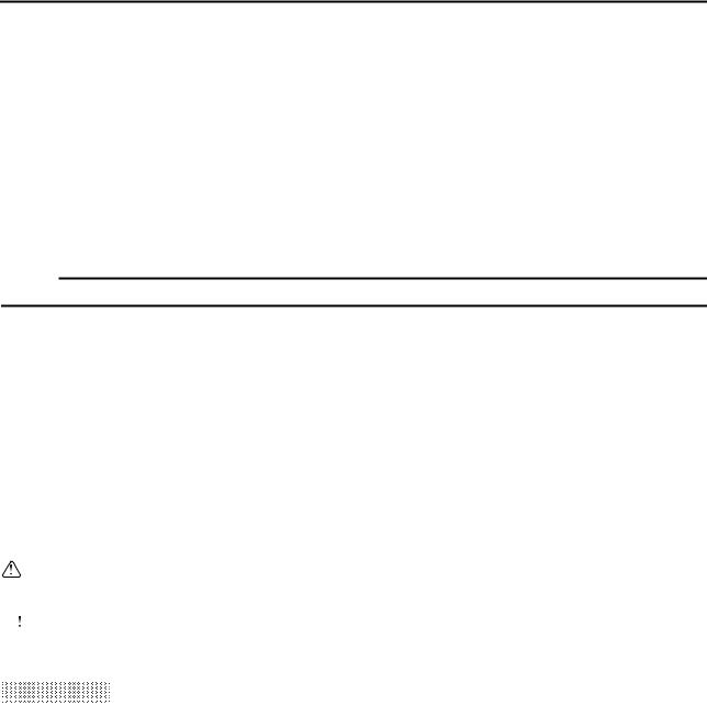
EXPLODED DIAGRAMS
To help identify parts and clarify procedure steps, there are exploded diagrams at the start of each removal and disassembly section.
1.An easy-to-see exploded diagram 4 is provided for removal and disassembly jobs.
2.Numbers 5 are given in the order of the jobs in the exploded diagram. A number that is enclosed by a circle indicates a disassembly step.
3.An explanation of jobs and notes is presented in an easy-to-read way by the use of symbol marks
6.The meanings of the symbol marks are given on the next page.
4.A job instruction chart 7 accompanies the exploded diagram, providing the order of jobs, names of parts, notes in jobs, etc.
5.For jobs requiring more information, the step-by-step format supplements 8 are given in addition to the exploded diagram and the job instruction chart.

1 |
|
2 |
|
|
GEN |
|
SPEC |
|
|
INFO |
|
|
||
|
|
|
|
|
3 |
|
4 |
|
|
CHK |
|
CHAS |
|
|
ADJ |
|
|
||
|
|
|
|
|
5 |
|
6 |
|
|
ENG |
|
COOL |
|
|
7 |
|
8 |
|
|
CARB |
|
ELEC – |
+ |
|
9 |
|
0 |
|
|
TRBL |
|
|
|
|
SHTG |
|
|
|
|
A |
|
B |
|
|
C |
|
D |
|
|
|
|
|
T |
|
|
|
|
. |
|
|
|
|
R |
|
|
|
|
. |
|
E |
F |
G |
|
|
H |
I |
J |
|
|
E |
|
G |
M |
|
K |
L |
M |
N |
|
B |
LS |
M |
|
S |
O |
|
P |
|
|
LT |
|
|
New |
|
|
|
|
|
|
EB003000
ILLUSTRATED SYMBOLS
Illustrated symbols 1 to 9 are printed on the top right of each page and indicate the subject of each chapter.
1 General information
2Specifications
3Periodic checks and adjustments
4Chassis
5Engine
6Cooling system
7Carburetion
8Electrical
9Troubleshooting
Illustrated symbols 0 to G are used to identify the specifications appearing in the text.
0 Can be serviced with engine mounted A Filling fluid
BLubricant
CSpecial tool
DTorque
EWear limit, clearance
FEngine speed
GΩ, V, A
Illustrated symbols H to N in the exploded diagrams indicate the types of lubricants and lubrication points.
H Apply engine oil I Apply gear oil
J Apply molybdenum disulfide oil K Apply wheel bearing grease
L Apply lightweight lithium soap base grease M Apply molybdenum disulfide grease
N Apply silicon grease
Illustrated symbols O to P in the exploded diagrams indicate where to apply a locking agent O and when to install a new part P.
OApply the locking agent (LOCTITEâ)
PReplace

TABLE OF CONTENTS
GENERAL INFORMATION |
|
|
|
|
|
|
|
|
|
|
|
GEN |
|
1 |
|||||||||
|
INFO |
|
|||||||||
|
|
|
|
|
|
|
|
|
|
|
|
SPECIFICATIONS |
|
|
|
|
|
|
|
|
|
|
|
SPEC |
|
2 |
|||||||||
|
|
||||||||||
|
|
|
|
|
|
|
|
|
|
|
|
PERIODIC CHECKS AND |
|
|
|
|
|
|
|
|
|
|
|
ADJUSTMENTS |
CHK |
|
3 |
||||||||
ADJ |
|
||||||||||
|
|
|
|
|
|
|
|
|
|
|
|
CHASSIS |
|
|
|
|
|
|
|
|
|
|
|
CHAS |
|
4 |
|||||||||
|
|
||||||||||
|
|
|
|
|
|
|
|
|
|
|
|
ENGINE |
|
|
|
|
|
|
|
|
|
|
|
ENG |
|
5 |
|||||||||
|
|
||||||||||
|
|
|
|
|
|
|
|
|
|
|
|
COOLING SYSTEM |
|
|
|
|
|
|
|
|
|
|
|
|
|
|
|
|
|
|
|
|
|
|
|
COOL |
|
6 |
|||||||||
|
|
||||||||||
|
|
|
|
|
|
|
|
|
|
|
|
CARBURETION |
|
|
|
|
|
|
|
|
|
|
|
|
|
|
|
|
|
|
|
|
|
|
|
|
|
|
|
|
|
|
|
|
|
|
|
CARB |
|
7 |
|||||||||
|
|
||||||||||
|
|
|
|
|
|
|
|
|
|
|
|
|
|
|
|
|
|
|
|
|
|||
|
|
|
– |
+ |
|
|
|||||
ELECTRICAL |
|
|
|
|
|
|
|
|
|
|
|
|
|
|
|
|
|
|
|
|
|
|
|
ELEC |
|
8 |
|||||||||
|
|
||||||||||
TROUBLESHOOTING |
|
|
TRBL |
9 |
|
|
SHTG |

INFOGEN 1

|
|
|
|
|
|
|
GEN |
|
|
|
|
INFO |
|
|
CHAPTER 1. |
|
|
|
|
|
|
|
|
|
GENERAL INFORMATION |
|
|
|
|
MACHINE IDENTIFICATION .......................................................................... |
1-1 |
|
|
|
VEHICLE IDENTIFICATION NUMBER .................................................... |
1-1 |
|
|
|
MODEL LABEL ......................................................................................... |
1-1 |
|
|
|
IMPORTANT INFORMATION ........................................................................ |
1-2 |
|
|
|
PREPARATION FOR REMOVAL PROCEDURES .................................. |
1-2 |
|
|
|
REPLACEMENT PARTS .......................................................................... |
1-2 |
|
|
|
GASKETS, OIL SEALS AND O-RINGS ................................................... |
1-2 |
|
|
|
LOCK WASHERS/PLATES AND COTTER PINS .................................... |
1-3 |
|
|
|
BEARINGS AND OIL SEALS ................................................................... |
1-3 |
|
|
|
CIRCLIPS ................................................................................................. |
1-3 |
|
|
|
CHECKING OF CONNECTIONS ................................................................... |
1-4 |
|
|
|
SPECIAL TOOLS ........................................................................................... |
1-5 |
|
|
|

GEN INFO
GEN
MACHINE IDENTIFICATION INFO
GENERAL INFORMATION
MACHINE IDENTIFICATION
VEHICLE IDENTIFICATION NUMBER
The vehicle identification number 1 is stamped into the left side of the frame.
MODEL LABEL
The model label 1 is affixed to the air filter case cover. This information will be needed to order spare parts.
1 - 1

IMPORTANT INFORMATION
EB101000
GEN INFO
IMPORTANT INFORMATION
PREPARATION FOR REMOVAL PROCEDURES
1.Remove all dirt, mud, dust and foreign material before removal and disassembly.
2.Use proper tools and cleaning equipment. Refer to the “SPECIAL TOOLS” section.
3.When disassembling the machine, always keep mated parts together. This includes gears, cylinder, piston and other parts that have been “mated” through normal wear. Mated parts must always be reused or replaced as an assembly.
4.During machine disassembly, clean all parts and place them in trays in the order of disassembly. This will speed up assembly and allow for the correct installation of all parts.
5.Keep all parts away from any source of fire.
EB101010
REPLACEMENT PARTS
1.Use only genuine Yamaha parts for all replacements. Use oil and grease recommended by Yamaha for all lubrication jobs. Other brands may be similar in function and appearance, but inferior in quality.
EB101020
GASKETS, OIL SEALS AND O-RINGS
1.Replace all gaskets, seals and O-rings when overhauling the engine. All gasket surfaces, oil seal lips and O-rings must be cleaned.
2.Properly oil all mating parts and bearings during reassembly. Apply grease to the oil seal lips.
1 - 2

IMPORTANT INFORMATION
EB101030
GEN INFO
LOCK WASHERS/PLATES AND COTTER PINS
1.Replace all lock washers/plates 1 and cotter pins after removal. Bend lock tabs along the bolt or nut flats after the bolt or nut has been tightened to specification.
EB101040
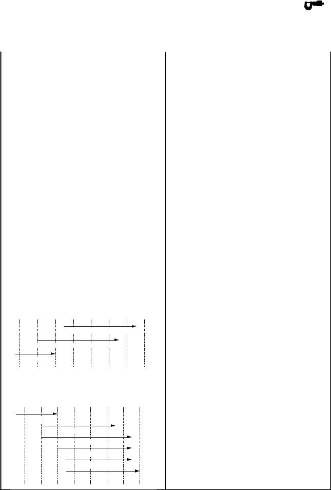
BEARINGS AND OIL SEALS
1.Install bearings and oil seals so that the manufacturer’s marks or numbers are visible. When installing oil seals, apply a light coating of lightweight lithium base grease to the seal lips. Oil bearings liberally when installing, if appropriate.
1 Oil seal
 CAUTION:
Do not use compressed air to spin the bearings dry. This will damage the bearing surfaces.
1 Bearing
EB101050
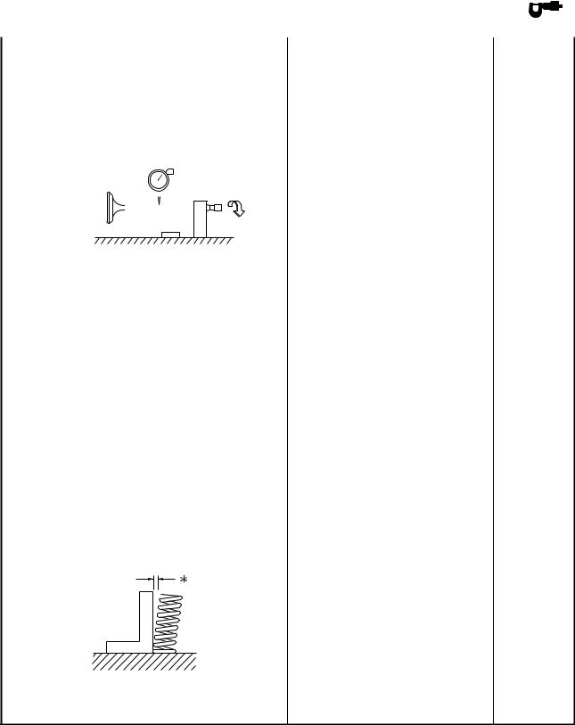
CIRCLIPS
1.Check all circlips carefully before reassembly. Always replace piston pin clips after one use. Replace distorted circlips. When installing a circlip 1, make sure that the sharpedged corner 2 is positioned opposite the thrust 3 it receives. See sectional view.
4 Shaft
1 - 3

CHECKING OF CONNECTIONS
EB801000
GEN INFO
CHECKING OF CONNECTIONS
Check the connectors for stains, rust, moisture, etc.
1.Disconnect:
●Connector 2.Check:
●Connector
Moisture → Dry each terminal with an air
blower.
Stains/rust → Connect and disconnect the terminals several times.
3.Check:
●Connector leads
Looseness → Bend up the pin 1 and connect the terminals.
4.Connect:
● Connector terminals
NOTE:
The two terminals “click” together.
5.Check:
● Continuity (using a pocket tester)
NOTE:
●If there is no continuity, clean the terminals.
●When checking the wire harness be sure to perform steps 1 to 3.
●As a quick remedy, use a contact revitalizer available at most part stores.
●Check the connector with a pocket tester as shown.
1 - 4

SPECIAL TOOLS
EB102001
SPECIAL TOOLS
GEN INFO
The following special tools are necessary for complete and accurate tune-up and assembly. Use only the appropriate special tools; this will help prevent damage caused by the use of inappropriate tools or improvised techniques. Special tools may differ by shape and part number from country to country. In such a case, two types are provided.
When placing an order, refer to the list provided below to avoid any mistakes.
For US and CDN
P/N. YM-, YU-, YS-, YK-, ACC-
Except for US and CDN
P/N. 90890-
Tool No. |
Tool name/How to use |
Illustration |
|
|
|
Bolt |
Slide hammer bolt (M6)/weight/set |
|
|
||
|
|
|
90890-01083 |
|
|
Weight |
|
|
90890-01084 |
|
|
Set |
These tools are used to remove the rocker |
|
YU-01083-A |
|
|
arm shaft. |
|
|
|
|
|
|
|
|
90890-01135 |
Crankcase separating tool |
|
|
||
|
|
|
YU-01135-A |
|
|
|
This tool is used to separate the crank- |
|
|
case. |
|
|
|
|
|
Crankshaft installer pot |
|
|
|
|
Pot |
Crankshaft installer bolt |
|
90890-01274 |
|
|
Bolt |
|
|
90890-01275 |
These tools are used to install the crank- |
|
|
|
|
|
shaft. |
|
|
|
|
YU-90050 |
Crankshaft installer set |
|
|
||
|
|
|
|
These tools are used to install the crank- |
|
|
shaft. |
|
|
|
|
Adapter |
Adapter |
|
|
||
Spacer (crankshaft installer) |
|
|
90890-04059 |
|
|
YM-90069 |
|
|
Spacer |
|
|
90890-04081 |
These tools are used to install the crank- |
|
YM-91044 |
|
|
shaft. |
|
|
|
|
|
|
|
|
90890-01016 |
Spacer |
|
|
||
|
|
|
|
This tool is used to install the crankshaft. |
|
|
|
|
1 - 5

|
|
|
|
|
|
|
|
|
|
|
|
SPECIAL TOOLS |
|
|
|
GEN |
|
|
|
|
|
|
|
|
INFO |
|
|
|
|
|||
|
|
|
|
|
|
|
|
|
|
|
|
|
|
|
|
|
|
|
|||
Tool No. |
Tool name/How to use |
Illustration |
|
|||||||
|
|
|
|
|
|
|
|
|
|
|
90890-01304 |
Piston pin puller |
|
|
|
|
|
|
|
|
|
|
|
|
|
|
|
|
|
|
||
|
|
|
|
|
|
|
|
|
|
|
YU-01304 |
|
|
|
|
|
|
|
|
|
|
|
This tool is used to remove the piston pin. |
|
|
|
|
|
|
|
|
|
|
|
|
|
|
|
|
|
|
|
|
90890-01311 |
Tappet adjusting tool (3 mm) |
|
|
|
|
|
|
|
|
|
|
|
|
|
|
|
|
|
|
||
|
|
|
|
|
|
|
|
|
|
|
YM-08035 |
|
|
|
|
|
|
|
|
|
|
|
This tool is necessary for adjusting the |
|
|
|
|
|
|
|
|
|
|
valve clearance. |
|
|
|
|
|
|
|
|
|
|
|
|
|
|
|
|
|
|
|
|
90890-01312 |
Fuel level gauge |
|
|
|
|
|
|
|
|
|
|
|
|
|
|
|
|
|
|
||
|
|
|
|
|
|
|
|
|
|
|
YM-01312-A |
|
|
|
|
|
|
|
|
|
|
|
This gauge is used to measure the fuel |
|
|
|
|
|
|
|
|
|
|
level in the float chamber. |
|
|
|
|
|
|
|
|
|
|
|
|
|
|
|
|
|
|
|
|
90890-01325 |
Radiator cap tester |
|
|
|
|
|
|
|
|
|
|
|
|
|
|
|
|
|
|
||
|
|
|
|
|
|
|
|
|
|
|
YU-24460-01 |
|
|
|
|
|
|
|
|
|
|
|
This tool is used to check the cooling sys- |
|
|
|
|
|
|
|
|
|
|
tem. |
|
|
|
|
|
|
|
|
|
|
|
|
|
|
|
|
|
|
|
|
90890-01352 |
Adapter |
|
|
|
|
|
|
|
|
|
|
|
|
|
|
|
|
|
|
||
|
|
|
|
|
|
|
|
|
|
|
YU-33984 |
|
|
|
|
|
|
|
|
|
|
|
This tool is used to check the cooling sys- |
|
|
|
|
|
|
|
|
|
|
tem. |
|
|
|
|
|
|
|
|
|
|
|
|
|
|
|
|
|
|
|
|
90890-01327 |
Damper rod holder (30 mm) |
|
|
|
|
|
|
|
|
|
|
|
|
|
|
|
|
|
|
||
|
|
|
|
|
|
|
|
|
|
|
YM-01327 |
|
|
|
|
|
|
|
|
|
|
|
This tool is needed to loosen and tighten |
|
|
|
|
|
|
|
|
|
|
the steering stem bearing retainer. |
|
|
|
|
|
|
|
|
|
|
|
|
|
|
|
|
|
|
|
|
|
|
|
|
|
|
|
|
|
|
|
90890-01362 |
Flywheel puller |
|
|
|
|
|
|
|
|
|
|
|
|
|
|
|
|
|
|
||
|
|
|
|
|
|
|
|
|
|
|
YU-33270 |
|
|
|
|
|
|
|
|
|
|
|
These tools are needed to remove the |
|
|
|
|
|
|
|
|
|
|
rotor. |
|
|
|
|
|
|
|
|
|
|
|
|
|
|
|
|
|
|
|
|
|
|
|
|
|
|
|
|
|
|
|
90890-01419 |
Axle nut wrench (50 mm) |
|
|
|
|
|
|
|
|
|
|
|
|
|
|
|
|
|
|
||
|
|
|
|
|
|
|
|
|
|
|
YM-37132 |
|
|
|
|
|
|
|
|
|
|
|
This tool is needed to loosen or tighten the |
|
|
|
|
|
|
|
|
|
|
rear axle nut. |
|
|
|
|
|
|
|
|
|
|
|
|
|
|
|
|
|
|
|
|
|
|
|
|
|
|
|
|
|
|
|
1 - 6

|
|
|
|
|
|
|
|
|
|
|
|
SPECIAL TOOLS |
|
|
GEN |
|
|
|
|
||
|
|
|
INFO |
|
|
|
|
|||
|
|
|
|
|
|
|
|
|
|
|
|
|
|
|
|
|
|
|
|
||
Tool No. |
Tool name/How to use |
Illustration |
|
|||||||
|
|
|
|
|
|
|
|
|
|
|
90890-01469 |
Oil filter wrench |
|
|
|
|
|
|
|
|
|
|
|
|
|
|
|
|
|
|||
|
|
|
|
|
|
|
|
|
|
|
YM-01469 |
|
|
|
|
|
|
|
|
|
|
|
This tool is needed to loosen or tighten |
|
|
|
|
|
|
|
|
|
|
the oil filter cartridge. |
|
|
|
|
|
|
|
|
|
|
|
|
|
|
|
|
|
|
|
|
|
Ball joint remover/installer set |
|
|
|
|
|
|
|
|
|
90890-01474 |
|
|
|
|
|
|
|
|
|
|
YM-01474 |
|
|
|
|
|
|
|
|
|
|
|
These tools are used to removing or |
|
|
|
|
|
|
|
|
|
|
installing the ball joint. |
|
|
|
|
|
|
|
|
|
|
|
|
|
|
|
|
|
|
|
|
|
Ball joint remover/installer attachment set |
|
|
|
|
|
|
|
|
|
90890-01480 |
|
|
|
|
|
|
|
|
|
|
YM-01480 |
|
|
|
|
|
|
|
|
|
|
|
These tools are used to removing or |
|
|
|
|
|
|
|
|
|
|
installing the ball joint. |
|
|
|
|
|
|
|
|
|
|
|
|
|
|
|
|
|
|
|
|
90890-01701 |
Sheave holder |
|
|
|
|
|
|
|
|
|
|
|
|
|
|
|
|
|
|||
|
|
|
|
|
|
|
|
|
|
|
YS-01880 |
This tool is needed to hold the AC mag- |
|
|
|
|
|
|
|
|
|
|
neto rotor when removing or installing the |
|
|
|
|
|
|
|
|
|
|
AC magneto rotor bolts. |
|
|
|
|
|
|
|
|
|
|
|
|
|
|
|
|
|
|
|
|
Set |
Compression gauge set |
|
|
|
|
|
|
|
|
|
|
|
|
|
|
|
|
|
|
||
Adapter |
|
|
|
|
|
|
|
|
|
|
90890-03081 |
|
|
|
|
|
|
|
|
|
|
YU-33223 |
|
|
|
|
|
|
|
|
|
|
Adapter |
|
|
|
|
|
|
|
|
|
|
90890-04082 |
These tools are needed to measure |
|
|
|
|
|
|
|
|
|
YU-33223-3 |
|
|
|
|
|
|
|
|
|
|
engine compression. |
|
|
|
|
|
|
|
|
|
|
|
|
|
|
|
|
|
|
|
|
|
|
|
|
|
|
|
|
|
|
|
|
90890-03112 |
Pocket tester |
|
|
|
|
|
|
|
|
|
|
|
|
|
|
|
|
|
|||
|
|
|
|
|
|
|
|
|
|
|
YU-03112 |
|
|
|
|
|
|
|
|
|
|
|
This instrument is needed for checking the |
|
|
|
|
|
|
|
|
|
|
electrical system. |
|
|
|
|
|
|
|
|
|
|
|
|
|
|
|
|
|
|
||
|
|
|
|
|
|
|
|
|
|
|
90890-03141 |
Timing light |
|
|
|
|
|
|
|
|
|
|
|
|
|
|
|
|
|
|||
|
|
|
|
|
|
|
|
|
|
|
YM-33277-A |
|
|
|
|
|
|
|
|
|
|
|
This tool is necessary for checking ignition |
|
|
|
|
|
|
|
|
|
|
timing. |
|
|
|
|
|
|
|
|
|
|
|
|
|
|
|
|
|
|
|
|
|
Carburetor angle driver |
|
|
|
|
|
|
|
|
|
90890-03158 |
|
|
|
|
|
|
|
|
|
|
|
This tool is used to turn the pilot screw |
|
|
|
|
|
|
|
|
|
|
when adjusting the engine idling speed. |
|
|
|
|
|
|
|
|
|
|
|
|
|
|
|
|
|
|
|
|
1 - 7

|
|
|
|
|
|
|
|
|
SPECIAL TOOLS |
|
|
GEN |
|
|
|
|
|
|
INFO |
|
|
||
|
|
|
|
|
|
|
|
|
|
|
|
|
|||
Tool No. |
Tool name/How to use |
Illustration |
|
||||
|
|
|
|
|
|
|
|
Compressor |
Valve spring compressor |
|
|
|
|
|
|
|
|
|
|
|
|
||
Valve spring compressor attachment |
|
|
|
|
|
|
|
90890-04019 |
|
|
|
|
|
|
|
YM-04019 |
|
|
|
|
|
|
|
Attachment |
This tool is needed to remove and install |
|
|
|
|
|
|
90890-01243 |
|
|
|
|
|
|
|
|
the valve assemblies. |
|
|
|
|
|
|
|
|
|
|
|
|
|
|
Middle driven shaft |
Middle driven shaft bearing driver |
|
|
|
|
|
|
|
|
|
|
|
|
||
bearing driver |
Mechanical seal installer |
|
|
|
|
|
|
90890-04058 |
|
|
|
|
|
|
|
|
|
|
|
|
|
|
|
YM-04058-1 |
|
|
|
|
|
|
|
Mechanical seal |
|
|
|
|
|
|
|
installer |
These tools are used to install the water |
|
|
|
|
|
|
90890-04078 |
|
|
|
|
|
|
|
pump seal. |
|
|
|
|
|
|
|
YM-33221 |
|
|
|
|
|
|
|
|
|
|
|
|
|
||
|
|
|
|
|
|
|
|
90890-04064 |
Valve guide remover (ø 6) |
|
|
|
|
|
|
|
|
|
|
|
|
||
|
|
|
|
|
|
|
|
YM-4064-A |
|
|
|
|
|
|
|
|
This tool is needed to remove and install |
|
|
|
|
|
|
|
the valve guide. |
|
|
|
|
|
|
|
|
|
|
|
|
|
|
90890-04065 |
Valve guide installer (ø 6) |
|
|
|
|
|
|
|
|
|
|
|
|
||
|
|
|
|
|
|
|
|
YM-04065-A |
|
|
|
|
|
|
|
|
This tool is needed to install the valve |
|
|
|
|
|
|
|
guide. |
|
|
|
|
|
|
|
|
|
|
|
|
|
|
90890-04066 |
Valve guide reamer (ø 6) |
|
|
|
|
|
|
|
|
|
|
|
|
||
|
|
|
|
|
|
|
|
YM-04066 |
|
|
|
|
|
|
|
|
This tool is needed to rebore the new |
|
|
|
|
|
|
|
valve guide. |
|
|
|
|
|
|
|
|
|
|
|
|
|
|
90890-04086 |
Clutch holding tool |
|
|
|
|
|
|
|
|
|
|
|
|
||
|
|
|
|
|
|
|
|
YM-91042 |
This tool is needed to hold the clutch car- |
|
|
|
|
|
|
|
rier when removing or installing the carrier |
|
|
|
|
|
|
|
nut. |
|
|
|
|
|
|
|
|
|
|
|
|
|
|
|
|
|
|
|
|
|
|
90890-06754 |
Ignition checker |
|
|
|
|
|
|
|
|
|
|
|
|
||
|
|
|
|
|
|
|
|
|
This instrument is necessary for checking |
|
|
|
|
|
|
|
the ignition system components. |
|
|
|
|
|
|
|
|
|
|
|
|
|
|
|
|
|
|
|
|
|
|
YM-34487 |
Dynamic spark tester |
|
|
|
|
|
|
|
|
|
|
|
|
||
|
|
|
|
|
|
|
|
|
This instrument is necessary for checking |
|
|
|
|
|
|
|
the ignition system components. |
|
|
|
|
|
|
|
|
|
|
|
|
|
|
|
|
|
|
|
|
|
|
1 - 8

|
|
|
|
|
|
|
|
|
|
SPECIAL TOOLS |
|
GEN |
|
|
|
|
|
|
INFO |
|
|
||
|
|
|
|
|
|
|
|
|
|
|
|
|
|||
Tool No. |
Tool name/How to use |
|
Illustration |
|
|||
|
|
|
|
|
|
|
|
|
Yamaha bond No. 1215 |
|
|
|
|
|
|
|
|
|
|
|
|
|
|
Bond |
Sealant (Quick Gasket®) |
|
|
|
|
|
|
90890-85505 |
|
|
|
|
|
|
|
Sealant |
|
|
|
|
|
|
|
ACC-11001-05-01 |
This sealant (bond) is used on crankcase |
|
|
|
|
|
|
|
|
|
|||||
|
mating surfaces, etc. |
|
|
|
|
|
|
|
|
|
|
|
|
|
|
1 - 9

GEN INFO
1 - 10
SPEC 2

|
|
SPEC |
|
|
|
|
|
|
|
CHAPTER 2. |
|
|
|
|
|
|
|
|
|
SPECIFICATIONS |
|
|
|
|
GENERAL SPECIFICATIONS ....................................................................... |
2-1 |
|
|
|
MAINTENANCE SPECIFICATIONS .............................................................. |
2-4 |
|
|
|
ENGINE .................................................................................................... |
2-4 |
|
|
|
CHASSIS ................................................................................................ |
2-14 |
|
|
|
ELECTRICAL ......................................................................................... |
2-18 |
|
|
|
HOW TO USE THE CONVERSION TABLE ................................................. |
2-20 |
|
|
|
GENERAL TORQUE SPECIFICATIONS ..................................................... |
2-20 |
|
|
|
LUBRICATION POINTS AND LUBRICANT TYPES ................................... |
2-21 |
|
|
|
ENGINE .................................................................................................. |
2-21 |
|
|
|
COOLANT FLOW DIAGRAMS .................................................................... |
2-22 |
|
|
|
OIL FLOW DIAGRAMS ................................................................................ |
2-23 |
|
|
|
CABLE ROUTING ........................................................................................ |
2-27 |
|
|
|

SPEC
GENERAL SPECIFICATIONS |
|
SPEC |
|
|
|
|
|
|
|
|
|
|
|
|
|
|
|
|
|
|
SPECIFICATIONS |
||||||
GENERAL SPECIFICATIONS |
|
|
|
|
|
|
|
|
|
||||
Item |
Standard |
|||||
|
|
|||||
Model code: |
5LP2 : (For CDN) |
|
||||
|
5LP4 : (For Europe) |
|||||
|
|
|
|
|
|
|
Dimensions: |
|
|
|
|
|
|
Overall length |
1,830 mm (72.0 in) |
|||||
Overall width |
1,100 mm (43.3 in) |
|||||
Overall height |
1,150 mm (45.3 in) |
|||||
Seat height |
860 mm (33.9 in) |
|||||
Wheelbase |
1,245 mm (49.0 in) |
|||||
Minimum ground clearance |
265 mm (10.4 in) |
|||||
Minimum turning radius |
3,300 mm (129.9 in) |
|||||
|
|
|
|
|
|
|
Basic weight: |
|
|
|
|
|
|
With oil and full fuel tank |
193 kg (426 lb) |
|||||
|
|
|
|
|
|
|
Engine: |
|
|
|
|
|
|
Engine type |
Liquid-cooled 4-stroke, SOHC |
|||||
Cylinder arrangement |
Forward-inclined single cylinder |
|||||
Displacement |
660 cm3 |
|||||
Bore × stroke |
100.0 × 84.0 mm (3.94 × 3.31 in) |
|||||
Compression ratio |
9.2 : 1 |
|
|
|
|
|
Standard compression pressure (at sea level) |
1,250 kPa (12.5 kg/cm2, 181 psi) |
|||||
Starting system |
Electric starter |
|||||
|
|
|||||
Lubrication system: |
Dry sump |
|
||||
|
|
|
|
|
|
|
Oil type or grade: |
|
|
|
|
|
|
Engine oil |
|
|
|
|
|
|
For CDN |
|
|
|
|
|
|
0° |
10° |
30° |
50° |
70° |
90° |
110° |
130°F |
API service SE, SF, SG type or higher |
|
|
|
|
|
|
|
|
|
|
|
YAMALUBE 4 (20W40) or SAE 20W40 |
|
|||||
|
YAMALUBE 4 (10W30) or SAE 10W30 |
|
|
|
||||
SAE 5W30 |
|
|
|
|
|
|
|
|
-20° |
-10° |
0° |
10° |
20° |
30° |
40° |
50°C |
|
For Europe
|
Temp. |
|
|
|
|
|
-20° -10° |
0° |
10° |
20° |
30° |
40° |
50°C |
5W/30 |
|
|
|
|
|
|
|
|
10W/30 |
|
|
|
|
|
|
10W/40 |
|
|
|
|
|
|
|
15W/40 |
|
|
|
|
|
|
20W/40 |
|
|
|
|
|
|
20W/50 |
|
|
|
2 - 1

|
GENERAL SPECIFICATIONS |
|
SPEC |
|
|
|
|
|
|
|
|
|
|
|
|
|
|
|
|
|
|
|
|
|
|||
Item |
|
Standard |
|
|||
|
|
|
|
|
|
|
Oil capacity: |
|
|
|
|
|
|
Engine oil |
|
|
|
|
|
|
Periodic oil change |
|
1.9 L (1.67 lmp qt, 2.01 US qt) |
|
|||
With oil filter replacement |
|
1.95 L (1.72 lmp qt, 2.06 US qt) |
|
|||
Total amount |
|
2.3 L (2.02 lmp qt, 2.43 US qt) |
|
|||
Radiator capacity (including all routes) |
1.3 L (1.14 lmp qt, 1.37 US qt) |
|
||||
|
|
|
|
|||
Air filter: |
|
Wet type element |
|
|||
|
|
|
|
|
|
|
Fuel: |
|
|
|
|
|
|
Type |
|
Regular unleaded fuel |
|
|||
Fuel tank capacity |
|
12 L (2.64 lmp gal, 3.17 US gal) |
|
|||
Fuel reserve amount |
|
2.6 L (0.57 lmp gal, 0.69 US gal) |
|
|||
|
|
|
|
|
|
|
Carburetor: |
|
|
|
|
|
|
Type/quantity |
|
BSR33/2 |
|
|||
Manufacturer |
|
MIKUNI |
|
|||
|
|
|
|
|
|
|
Spark plug: |
|
|
|
|
|
|
Type/manufacturer |
|
DPR8EA-9/NGK |
|
|||
Spark plug gap |
|
0.8 ~ 0.9 mm (0.031 ~ 0.035 in) |
|
|||
|
|
|
|
|||
Clutch type: |
|
Wet, multiple disc |
|
|||
|
|
|
|
|
|
|
Transmission: |
|
|
|
|
|
|
Primary reduction system |
|
Spur gear |
|
|||
Primary reduction ratio |
|
71/34 (2.088) |
|
|
|
|
Secondary reduction system |
|
Chain drive |
|
|||
Secondary reduction ratio |
|
40/13 (3.076) |
|
|
|
|
Transmission type |
|
Constant mesh, 5-speed/forward. |
|
|||
|
|
1-speed/reverse |
|
|||
Operation |
|
Left foot operation |
|
|||
Gear ratio |
|
|
|
|
|
|
1st gear |
|
34/14 (2.428) |
|
|
|
|
2nd gear |
|
29/19 (1.526) |
|
|
|
|
3rd gear |
|
26/21 (1.238) |
|
|
|
|
4th gear |
|
22/21 (1.047) |
|
|
|
|
5th gear |
|
19/21 (0.904) |
|
|
|
|
Reverse gear |
|
28/23 × 23 × 16 (1.750) |
|
|
|
|
|
|
|
|
|
|
|
Chassis: |
|
|
|
|
|
|
Frame type |
|
Steel tube frame |
|
|||
Caster angle |
|
8° |
|
|
|
|
Camber angle |
|
–1° |
|
|||
Kingpin angle |
|
14.5° |
|
|
|
|
Kingpin offset |
|
5 mm (0.20 in) |
|
|||
Trail |
|
47 mm (1.85 in) |
|
|||
Tread (STD) |
front |
925 mm (36.42 in) |
|
|||
|
rear |
840 mm (33.07 in) |
|
|||
Toe-in |
|
0 ~ 10 mm (0 ~ 0.39 in) |
|
|||
|
|
|
|
|
|
|
2 - 2

GENERAL SPECIFICATIONS SPEC
Item |
|
Standard |
|
|
|
Tire: |
|
|
Type |
|
Tubeless |
Size |
front |
AT21 × 7–10 |
|
rear |
AT20 × 10–9 |
Manufacturer |
front |
DUNLOP |
|
rear |
DUNLOP |
Type |
front |
KT331 Radial |
|
rear |
KT335 Radial |
|
|
|
Tire pressure (cold tire): |
|
|
Maximum load* |
|
100 kg (220 lb) |
Off-road riding |
front |
27.5 kPa (0.275 kg/cm2, 4.0 psi) |
|
rear |
27.5 kPa (0.275 kg/cm2, 4.0 psi) |
*Load in total weight of cargo, rider and acces- |
|
|
sories |
|
|
|
|
|
Brake: |
|
|
Front brake |
type |
Dual disc brake |
|
operation |
Right hand operation |
Rear brake |
type |
Single disc brake |
|
operation |
Right foot operation |
|
|
|
Suspension: |
|
|
Front suspension |
|
Double wishbone |
Rear suspension |
|
Swingarm (link suspension) |
|
|
|
Shock absorber: |
|
|
Front shock absorber |
|
Coil spring/oil damper |
Rear shock absorber |
|
Coil spring/gas-oil damper |
|
|
|
Wheel travel: |
|
|
Front wheel travel |
|
230 mm (9.06 in) |
Rear wheel travel |
|
220 mm (8.66 in) |
|
|
|
Electrical: |
|
|
Ignition system |
|
DC-C.D.I. |
Generator system |
|
A.C. magneto |
Battery type |
|
YTX14-BS |
Battery capacity |
|
12 V 12 Ah |
|
|
|
Headlight type: |
|
Krypton bulb |
|
|
|
Bulb voltage/wattage × quantity: |
|
12 V 30 W/30 W × 2 |
Headlight |
|
|
Tail/brake light |
|
12 V 5 W/21 W × 1 |
Indicator and warning lights |
|
12 V 1.7 W × 1 |
Neutral |
|
|
Reverse |
|
12 V 1.7 W × 1 |
Coolant temperature |
|
12 V 1.7 W × 1 |
|
|
|
2 - 3

MAINTENANCE SPECIFICATIONS SPEC
MAINTENANCE SPECIFICATIONS
ENGINE
Item |
Standard |
Limit |
|
|
|
Cylinder head: |
|
|
Warp limit |
---- |
0.05 mm |
|
|
(0.002 in) |
Cylinder: |
|
|
Bore size |
100.005 ~ 100.045 mm |
100.1 mm |
Measuring point * |
(3.9372 ~ 3.9388 in) |
(3.94 in) |
50 mm (2.0 in) |
---- |
Camshaft: |
|
|
Drive method |
Chain drive (Left) |
---- |
Camshaft cap inside diameter |
23.000 ~ 23.021 mm |
---- |
|
(0.9055 ~ 0.9063 in) |
|
Camshaft journal diameter |
22.967 ~ 22.980 mm |
---- |
|
(0.9042 ~ 0.9047 in) |
|
Camshaft journal-to-camshaft cap clearance |
0.020 ~ 0.054 mm |
---- |
|
(0.0008 ~ 0.0021 in) |
|
Cam dimensions |
|
|
C
A
|
|
|
|
|
|
|
|
|
|
|
|
|
|
|
|
|
|
|
|
B |
|
|
|
|
|
|
|
|
|
|
|
|
|
||
Intake |
|
|
“A” |
|
|
35.69 ~ 35.79 mm |
35.59 mm |
|
|
|
|
|
|
|
|
(1.4051 ~ 1.4091 in) |
(1.4012 in) |
|
|
|
“B” |
|
|
30.15 ~ 30.25 mm |
30.05 mm |
|
|
|
|
|
|
|
|
(1.1870 ~ 1.1909 in) |
(1.1831 in) |
|
|
|
“C” |
|
|
5.74 mm (0.2260 in) |
---- |
|
Exhaust |
|
|
“A” |
|
|
36.50 ~ 36.60 mm |
36.40 mm |
|
|
|
|
|
|
|
|
(1.437 ~ 1.441 in) |
(1.4331 in) |
|
|
|
“B” |
|
|
30.15 ~ 30.25 mm |
30.05 mm |
|
|
|
|
|
|
|
|
(1.187 ~ 1.191 in) |
(1.1831 in) |
|
|
|
“C” |
|
|
6.55 mm (0.2579 in) |
---- |
|
2 - 4

|
|
MAINTENANCE SPECIFICATIONS |
|
SPEC |
|
|
|
|||||||
|
|
|
|
|
|
|
|
|
|
|
|
|
|
|
|
|
|
|
|
|
|
|
|
|
|
|
|
|
|
|
|
|
|
|
|
|
|
|
|
|
|
|
|
|
Item |
|
|
|
|
|
|
|
Standard |
|
|
Limit |
|||
|
|
|
|
|
|
|
|
|
|
|
|
|||
Camshaft runout limit |
---- |
|
0.03 mm |
|
||||||||||
|
|
|
|
|
|
|
|
|
|
|
(0.0012 in) |
|||
|
|
|
|
|
|
|
|
|
|
|
|
|
|
|
|
|
|
|
|
|
|
|
|
|
|
|
|
|
|
|
|
|
|
|
|
|
|
|
|
|
|
|
|
|
|
|
|
|
|
|
|
|
|
|
|
|
|
|
|
|
|
|
|
|
|
|
|
|
|
|
|
|
|
|
|
|
|
|
|
|
|
|
|
|
|
|
|
|
|
Timing chain: |
|
|
|
|
|
|
||||
Timing chain type/No. of links |
|
75-RH2015/126 |
---- |
|||||||
Timing chain adjustment method |
|
Automatic |
---- |
|||||||
|
|
|
|
|
|
|
|
|
|
|
Rocker arm/rocker arm shaft: |
|
|
|
|
|
|
||||
Shaft outside diameter |
|
|
11.976 ~ 11.991 mm |
---- |
||||||
|
|
|
|
|
|
|
(0.4715 ~ 0.4721 in) |
|
|
|
Arm-to-shaft clearance |
|
|
0.009 ~ 0.042 mm |
---- |
||||||
|
|
|
|
|
|
|
(0.0004 ~ 0.0017 in) |
|
|
|
|
|
|
|
|
|
|
|
|
|
|
Valve, valve seat, valve guide: |
|
|
|
|
|
|||||
Valve clearance (cold) |
IN |
|
0.10 ~ 0.15 mm |
---- |
||||||
|
|
|
|
|
|
|
(0.0039 ~ 0.0059 in) |
|
|
|
|
|
|
|
|
EX |
|
0.15 ~ 0.20 mm |
---- |
||
|
|
|
|
|
|
|
(0.0059 ~ 0.0079 in) |
|
|
|
Valve dimensions |
|
|
|
|
|
|
||||
|
|
|
|
|
B |
|
C |
|
|
|
|
|
A |
|
|
|
|
Seat Width |
|
|
D |
|
|
|
|
|
|
|
|
|||
|
|
|
|
Face Width |
|
Margin Thickness |
||||
|
|
|
|
|||||||
|
Head Diameter |
|
||||||||
“A” head diameter |
IN |
|
29.9 ~ 30.1 mm |
|
|
---- |
||||
|
|
|||||||||
|
|
|
|
|
|
|
(1.1772 ~ 1.1850 in) |
|
|
|
|
|
|
|
|
EX |
|
31.9 ~ 32.1 mm |
|
|
---- |
|
|
|
|
|
|
|
(1.2559 ~ 1.2638 in) |
|
|
|
“B” face width |
IN |
|
2.25 mm (0.0886 in) |
|
|
---- |
||||
|
|
|
|
|
EX |
|
2.26 mm (0.0890 in) |
|
|
---- |
“C” seat width |
IN |
|
0.9 ~ 1.1 mm |
|
|
1.6 mm |
||||
|
|
|
|
|
|
|
(0.0354 ~ 0.0433 in) |
|
|
(0.0630 in) |
|
|
|
|
|
EX |
|
0.9 ~ 1.1 mm |
|
|
1.6 mm |
|
|
|
|
|
|
|
(0.0354 ~ 0.0433 in) |
|
|
(0.0630 in) |
“D” margin thickness |
IN |
|
0.85 ~ 1.15 mm |
|
|
---- |
||||
|
|
|
|
|
|
|
(0.0335 ~ 0.0453 in) |
|
|
|
|
|
|
|
|
EX |
|
0.85 ~ 1.15 mm |
|
|
---- |
|
|
|
|
|
|
|
(0.0335 ~ 0.0453 in) |
|
|
|
Stem outside diameter |
IN |
|
5.975 ~ 5.990 mm |
|
|
5.945 mm |
||||
|
|
|
|
|
|
|
(0.2352 ~ 0.2358 in) |
|
|
(0.2341 in) |
|
|
|
|
|
EX |
|
5.960 ~ 5.975 mm |
|
|
5.930 mm |
|
|
|
|
|
|
|
(0.2346 ~ 0.2352 in) |
|
|
(0.2335 in) |
Guide inside diameter |
IN |
|
6.000 ~ 6.012 mm |
|
|
6.040 mm |
||||
|
|
|
|
|
|
|
(0.2362 ~ 0.2367 in) |
|
|
(0.2378 in) |
|
|
|
|
|
EX |
|
6.000 ~ 6.012 mm |
|
|
6.040 mm |
|
|
|
|
|
|
|
(0.2362 ~ 0.2367 in) |
|
|
(0.2378 in) |
|
|
|
|
|
|
|
|
|
|
|
2 - 5
|
|
|
|
|
|
|
|
|
MAINTENANCE SPECIFICATIONS |
|
SPEC |
|
|
|
||||||
|
|
|
|
|
|
|
|
|
|
|
|
|
|
|
|
|
|
|
|
|
|
|
|
|
|
|
|
|
|
|
|
|
|
|
|
|
|
|
|
|
|
|
|
|
|
|
|
|
|
|
|
|
|
|
|
|
|
|
|
|
|
|
|
|
|
|
|
Item |
|
|
|
|
|
|
|
Standard |
|
|
Limit |
||||
|
|
|
|
|
|
|
|
|
|
|
|
|
|
|
|
|
|
|||
Stem-to-guide clearance |
|
|
|
|
|
IN |
0.010 ~ 0.037 mm |
|
0.08 mm |
|
||||||||||
|
|
|
|
|
|
|
|
|
|
|
|
|
|
|
(0.0004 ~ 0.0015 in) |
|
(0.0031 in) |
|||
|
|
|
|
|
|
|
|
|
|
|
|
|
EX |
0.025 ~ 0.052 mm |
|
0.10 mm |
||||
|
|
|
|
|
|
|
|
|
|
|
|
|
|
|
(0.0010 ~ 0.0020 in) |
|
(0.0039 in) |
|||
Stem runout limit |
|
|
|
|
|
|
|
---- |
|
0.01 mm |
||||||||||
|
|
|
|
|
|
|
|
|
|
|
|
|
|
|
|
|
(0.0004 in) |
|||
|
|
|
|
|
|
|
|
|
|
|
|
|
|
|
|
|
|
|
|
|
|
|
|
|
|
|
|
|
|
|
|
|
|
|
|
|
|
|
|
|
|
|
|
|
|
|
|
|
|
|
|
|
|
|
|
|
|
|
|
|
|
|
|
|
|
|
|
|
|
|
|
|
|
|
|
|
|
|
|
|
|
|
|
|
|
|
|
|
|
|
|
|
|
|
|
|
|
|
|
|
|
|
|
|
|
|
|
|
|
|
|
|
|
|
|
|
|
|
|
|
|
|
|
|
|
Valve seat width |
IN |
0.9 ~ 1.1 mm |
1.6 mm |
|
|
(0.0354 ~ 0.0433 in) |
(0.0630 in) |
|
EX |
0.9 ~ 1.1 mm |
1.6 mm |
|
|
(0.0354 ~ 0.0433 in) |
(0.0630 in) |
|
|
|
|
Valve spring: |
|
|
|
Free length |
IN |
35.95 mm (1.42 in) |
34.15 mm |
|
|
|
(1.34 in) |
|
EX |
37.75 mm (1.49 in) |
35.86 mm |
|
|
|
(1.41 in) |
Set length (valve closed) |
IN |
27.2 mm (1.07 in) |
---- |
|
EX |
30.7 mm (1.21 in) |
---- |
Compressed pressure |
|
|
|
(installed) |
IN |
149 ~ 173 N (15.19 ~ 17.64 kg, |
---- |
|
|
33.50 ~ 38.89 lb) |
|
|
EX |
165 ~ 191 N (16.83 ~ 19.49 kg, |
---- |
Tilt limit* |
|
37.09 ~ 42.94 lb) |
|
IN |
---- |
2.5°/1.6 mm |
|
|
|
|
(2.5°/0.06 in) |
|
EX |
---- |
2.5°/1.6 mm |
|
|
|
(2.5°/0.06 in) |
Direction of winding |
|
|
|
(top view) |
IN |
Clockwise |
---- |
|
EX |
Clockwise |
---- |
2 - 6
|
MAINTENANCE SPECIFICATIONS |
|
SPEC |
|
|
|
|
|
|
|
|
|
|
|
|
|
|
|
|
|
|
|
|
|
|
|
|
|
|
|
|
|
Item |
Standard |
|
|
Limit |
||
|
|
|
|
|
|
|
|
Piston: |
|
|
|
|
|
|
|
Piston to cylinder clearance |
0.05 ~ 0.07 mm |
|
0.15 mm |
||||
|
|
(0.0020 ~ 0.0028 in) |
|
(0.0059 in) |
|||
Piston size “D” |
99.945 ~ 99.995 mm |
---- |
|
|
|||
|
|
(3.9348 ~ 3.9368 in) |
|
|
|
|
|
|
|
|
|
|
|
|
|
|
|
|
|
|
|
|
|
|
|
|
|
|
|
|
|
|
|
|
|
H |
|
||||||||||
D |
|
|
|
|
|
|
|
|
|
|
|
|
|||
Measuring point “H” |
|
|
|
|
|
|
|
|
|
|
2.5 mm (0.10 in) |
---- |
|||
Piston off-set |
|
|
|
|
|
|
|
|
|
|
1.0 mm (0.04 in) |
---- |
|||
Piston pin bore inside diameter |
|
|
|
|
|
|
|
|
|
|
22.004 ~ 22.015 mm |
22.045 mm |
|||
|
|
|
|
|
|
|
|
|
|
|
|
|
|
(0.8663 ~ 0.8667 in) |
(0.8679 in) |
Piston pin outside diameter |
|
|
|
|
|
|
|
|
|
|
21.991 ~ 22.000 mm |
21.971 mm |
|||
|
|
|
|
|
|
|
|
|
|
|
|
|
|
(0.8658 ~ 0.8661 in) |
(0.8650 in) |
|
|
|
|
|
|
|
|
|
|
|
|
|
|
|
|
Piston rings: |
|
|
|
|
|
|
|
|
|
|
|
|
|||
Top ring |
|
|
|
|
|
|
|
|
|
|
|
|
|||
|
|
|
|
|
|
|
|
|
|
|
|
|
|
|
|
|
|
|
|
|
|
|
|
|
|
|
|
|
B |
|
|
|
|
|
T |
|
|
|
|
|
|
|
|
|
|
|
|
|
|
|
|
|
|
|
|
|
|
|
|
|
|
|
|
|
|
|
|
|
|
|
|
|
|
|
|
|
|
|
|
Type |
|
|
|
|
|
|
|
|
|
|
Barrel |
---- |
|||
Dimensions (B × T) |
|
|
|
|
|
|
|
|
|
|
1.2 × 3.8 mm |
---- |
|||
|
|
|
|
|
|
|
|
|
|
|
|
|
|
(0.0472 × 0.1496 in) |
|
End gap (installed) |
|
|
|
|
|
|
|
|
|
|
0.30 ~ 0.45 mm |
0.70 mm |
|||
|
|
|
|
|
|
|
|
|
|
|
|
|
|
(0.0118 ~ 0.0177 in) |
(0.0276 in) |
Side clearance (installed) |
|
|
|
|
|
|
|
|
|
|
0.04 ~ 0.08 mm |
0.13 mm |
|||
|
|
|
|
|
|
|
|
|
|
|
|
|
|
(0.0016 ~ 0.0031 in) |
(0.0051 in) |
2nd ring |
|
|
|
|
|
|
|
|
|
|
|
|
|||
|
|
|
|
|
|
|
|
|
|
|
|
|
B |
|
|
|
|
|
|
|
|
|
|
|
|
|
|
|
|
||
|
|
|
T |
|
|
|
|
|
|
|
|
|
|
|
|
|
|
|
|
|
|
|
|
|
|
|
|
|
|
|
|
|
|
|
|
|
|
|
|
|
|
|
|
|
|
|
|
Type |
|
|
|
|
|
|
|
|
|
|
Taper |
---- |
|||
Dimensions (B × T) |
|
|
|
|
|
|
|
|
|
|
1.2 × 4.0 mm |
---- |
|||
|
|
|
|
|
|
|
|
|
|
|
|
|
|
(0.0472 × 0.1575 in) |
|
End gap (installed) |
|
|
|
|
|
|
|
|
|
|
0.30 ~ 0.45 mm |
0.80 mm |
|||
|
|
|
|
|
|
|
|
|
|
|
|
|
|
(0.0118 ~ 0.0177 in) |
(0.0315 in) |
Side clearance |
|
|
|
|
|
|
|
|
|
|
0.03 ~ 0.07 mm |
0.13 mm |
|||
|
|
|
|
|
|
|
|
|
|
|
|
|
|
(0.0012 ~ 0.0028 in) |
(0.0051 in) |
Oil ring |
|
|
|
|
|
|
|
|
|
|
|
|
|||
|
|
|
|
|
|
|
|
|
|
|
|
|
|||
|
|
|
|
|
|
|
|
|
|
B |
|
||||
|
|
|
|
|
|
|
|
|
|
|
|||||
|
|
|
|
|
|
|
|
|
|
||||||
|
|
|
|
|
|
|
|
|
|
|
|
|
|
|
|
|
|
|
T |
|
|
|
|
|
|
|
|
|
|
|
|
|
|
|
|
|
|
|
|
|
|
|
|
|
|
|
|
Dimensions (B × T) |
|
|
|
|
|
|
|
|
|
|
2.5 × 3.4 mm |
---- |
|||
|
|
|
|
|
|
|
|
|
|
|
|
|
|
(0.0984 × 0.1339 in) |
|
End gap (installed) |
|
|
|
|
|
|
|
|
|
|
0.2 ~ 0.7 mm |
---- |
|||
|
|
|
|
|
|
|
|
|
|
|
|
|
|
(0.0079 ~ 0.0276 in) |
|
2 - 7
Loading...