


 Loading...
Digital Sound Projector
Owner’s Manual
for North America, Central and South America, Australia, Asia and Taiwan models
Read the supplied booklet “Quick Reference Guide” before using the unit.
English

CONTENTS
FEATURES |
4 |
What you can do with this unit . . . . . . . . . . . . . . . . . . . . . . . . . . . . . . . . . . . . 4 Supplied accessories . . . . . . . . . . . . . . . . . . . . . . . . . . . . . . . . . . . . . . . . . . . . . 6
Preparing remote control . . . . . . . . . . . . . . . . . . . . . . . . . . . . . . . . . . . . . . . . . . . . . . . . . . . . . . . . . . . . . . . . . . . . . . . . . . 7
Controls and functions . . . . . . . . . . . . . . . . . . . . . . . . . . . . . . . . . . . . . . . . . . . 8
PREPARATIONS |
11 |
General setup procedure . . . . . . . . . . . . . . . . . . . . . . . . . . . . . . . . . . . . . . . . 11 aInstallation . . . . . . . . . . . . . . . . . . . . . . . . . . . . . . . . . . . . . . . . . . . . . . . . . . 12 bConnecting a TV . . . . . . . . . . . . . . . . . . . . . . . . . . . . . . . . . . . . . . . . . . . . . . 22 cConnecting playback devices . . . . . . . . . . . . . . . . . . . . . . . . . . . . . . . . . 23 dOther connections . . . . . . . . . . . . . . . . . . . . . . . . . . . . . . . . . . . . . . . . . . . . 25
Connecting a subwoofer . . . . . . . . . . . . . . . . . . . . . . . . . . . . . . . . . . . . . . . . . . . . . . . . . . . . . . . . . . . . . . . . . . . . . . . . . . 25 Wired network connections . . . . . . . . . . . . . . . . . . . . . . . . . . . . . . . . . . . . . . . . . . . . . . . . . . . . . . . . . . . . . . . . . . . . . . . 25
eConnecting the power cable . . . . . . . . . . . . . . . . . . . . . . . . . . . . . . . . . . 26 fInitial settings . . . . . . . . . . . . . . . . . . . . . . . . . . . . . . . . . . . . . . . . . . . . . . . 27
Displaying the menu screen on the TV . . . . . . . . . . . . . . . . . . . . . . . . . . . . . . . . . . . . . . . . . . . . . . . . . . . . . . . . . . . . . 27 Selecting the language for menu display . . . . . . . . . . . . . . . . . . . . . . . . . . . . . . . . . . . . . . . . . . . . . . . . . . . . . . . . . . . 28 Auto setup for appropriate surround effects (IntelliBeam) . . . . . . . . . . . . . . . . . . . . . . . . . . . . . . . . . . . . . . . . . . 29 Operating the unit by TV’s remote control (HDMI control) . . . . . . . . . . . . . . . . . . . . . . . . . . . . . . . . . . . . . . . . . . 34
PLAYBACK |
36 |
Basic operation for playback . . . . . . . . . . . . . . . . . . . . . . . . . . . . . . . . . . . . 36 Enjoying sound based on your preference . . . . . . . . . . . . . . . . . . . . . . . . 37
Playback with 3D surround sound . . . . . . . . . . . . . . . . . . . . . . . . . . . . . . . . . . . . . . . . . . . . . . . . . . . . . . . . . . . . . . . . . |
37 |
Playback with surround sound . . . . . . . . . . . . . . . . . . . . . . . . . . . . . . . . . . . . . . . . . . . . . . . . . . . . . . . . . . . . . . . . . . . . . |
38 |
Enjoying three-dimensional surround sound (CINEMA DSP 3D/CINEMA DSP) . . . . . . . . . . . . . . . . . . . . . . . . |
38 |
2-channel playback (stereo playback mode) . . . . . . . . . . . . . . . . . . . . . . . . . . . . . . . . . . . . . . . . . . . . . . . . . . . . . . . . |
40 |
Delivering sound to a specified location (target playback mode) . . . . . . . . . . . . . . . . . . . . . . . . . . . . . . . . . . . . |
40 |
Playing back digitally compressed formats (such as MP3, etc.) with enriched sound |
|
(Compressed Music Enhancer) . . . . . . . . . . . . . . . . . . . . . . . . . . . . . . . . . . . . . . . . . . . . . . . . . . . . . . . . . . . . . . . . . . . . . |
41 |
Clear playback of human voices (CLEAR VOICE) . . . . . . . . . . . . . . . . . . . . . . . . . . . . . . . . . . . . . . . . . . . . . . . . . . . . . |
41 |
Adjusting the position from which dialog is heard (Dialog Lift) . . . . . . . . . . . . . . . . . . . . . . . . . . . . . . . . . . . . . . |
41 |
Adjusting volume for each channel . . . . . . . . . . . . . . . . . . . . . . . . . . . . . . . . . . . . . . . . . . . . . . . . . . . . . . . . . . . . . . . . |
42 |
Using useful features . . . . . . . . . . . . . . . . . . . . . . . . . . . . . . . . . . . . . . . . . . . 43
Saving energy with the Eco function . . . . . . . . . . . . . . . . . . . . . . . . . . . . . . . . . . . . . . . . . . . . . . . . . . . . . . . . . . . . . . . 43 Switching information displayed in the front panel display . . . . . . . . . . . . . . . . . . . . . . . . . . . . . . . . . . . . . . . . . 43 Saving this unit’s settings to system memory . . . . . . . . . . . . . . . . . . . . . . . . . . . . . . . . . . . . . . . . . . . . . . . . . . . . . . . 44
Wireless playback of audio via Bluetooth connection . . . . . . . . . . . . . . 45
Listening to music from a Bluetooth device (Receiving) . . . . . . . . . . . . . . . . . . . . . . . . . . . . . . . . . . . . . . . . . . . . . 46 Listening to audio through Bluetooth speakers or headphones (transmitting) . . . . . . . . . . . . . . . . . . . . . . . 48
En 2

NETWORKS |
49 |
Network functions . . . . . . . . . . . . . . . . . . . . . . . . . . . . . . . . . . . . . . . . . . . . . |
. 49 |
Connecting to a network . . . . . . . . . . . . . . . . . . . . . . . . . . . . . . . . . . . . . . . |
. 50 |
Wired network connections . . . . . . . . . . . . . . . . . . . . . . . . . . . . . . . . . . . . . . . . . . . . . . . . . . . . . . . . . . . . . . . . . . . . |
. . . 51 |
Wireless network . . . . . . . . . . . . . . . . . . . . . . . . . . . . . . . . . . . . . . . . . . . . . . . . . . . . . . . . . . . . . . . . . . . . . . . . . . . . . . . |
. . . 51 |
Connecting a mobile device to the unit directly (Wireless Direct) . . . . . . . . . . . . . . . . . . . . . . . . . . . . . . . . |
. . . 58 |
Playing back music stored on media servers (PCs/NAS) . . . . . . . . . . . . 60
Media sharing setup . . . . . . . . . . . . . . . . . . . . . . . . . . . . . . . . . . . . . . . . . . . . . . . . . . . . . . . . . . . . . . . . . . . . . . . . . . . . . . 60 Playing music files . . . . . . . . . . . . . . . . . . . . . . . . . . . . . . . . . . . . . . . . . . . . . . . . . . . . . . . . . . . . . . . . . . . . . . . . . . . . . . . . 60
Listening to Internet radio . . . . . . . . . . . . . . . . . . . . . . . . . . . . . . . . . . . . . . . 61
Playback of Internet radio . . . . . . . . . . . . . . . . . . . . . . . . . . . . . . . . . . . . . . . . . . . . . . . . . . . . . . . . . . . . . . . . . . . . . . . . . 61 Registering favorite Internet radio stations . . . . . . . . . . . . . . . . . . . . . . . . . . . . . . . . . . . . . . . . . . . . . . . . . . . . . . . . . 61
Playing back music with AirPlay . . . . . . . . . . . . . . . . . . . . . . . . . . . . . . . . . 63
Playback of iTunes/iPod music contents . . . . . . . . . . . . . . . . . . . . . . . . . . . . . . . . . . . . . . . . . . . . . . . . . . . . . . . . . . . 63
Playing back music stored on mobile devices . . . . . . . . . . . . . . . . . . . . . 65
Using a mobile device to play songs . . . . . . . . . . . . . . . . . . . . . . . . . . . . . . . . . . . . . . . . . . . . . . . . . . . . . . . . . . . . . . . 65
SETTINGS |
66 |
Setup menu . . . . . . . . . . . . . . . . . . . . . . . . . . . . . . . . . . . . . . . . . . . . . . . . . . . . 66
Setting the setup menu . . . . . . . . . . . . . . . . . . . . . . . . . . . . . . . . . . . . . . . . . . . . . . . . . . . . . . . . . . . . . . . . . . . . . . . . . . . 66 Setup menu list . . . . . . . . . . . . . . . . . . . . . . . . . . . . . . . . . . . . . . . . . . . . . . . . . . . . . . . . . . . . . . . . . . . . . . . . . . . . . . . . . . . 67 Beam . . . . . . . . . . . . . . . . . . . . . . . . . . . . . . . . . . . . . . . . . . . . . . . . . . . . . . . . . . . . . . . . . . . . . . . . . . . . . . . . . . . . . . . . . . . . . 69 Sound . . . . . . . . . . . . . . . . . . . . . . . . . . . . . . . . . . . . . . . . . . . . . . . . . . . . . . . . . . . . . . . . . . . . . . . . . . . . . . . . . . . . . . . . . . . . 74 HDMI . . . . . . . . . . . . . . . . . . . . . . . . . . . . . . . . . . . . . . . . . . . . . . . . . . . . . . . . . . . . . . . . . . . . . . . . . . . . . . . . . . . . . . . . . . . . . 76 Display . . . . . . . . . . . . . . . . . . . . . . . . . . . . . . . . . . . . . . . . . . . . . . . . . . . . . . . . . . . . . . . . . . . . . . . . . . . . . . . . . . . . . . . . . . . 77 Information . . . . . . . . . . . . . . . . . . . . . . . . . . . . . . . . . . . . . . . . . . . . . . . . . . . . . . . . . . . . . . . . . . . . . . . . . . . . . . . . . . . . . . . 78 Network . . . . . . . . . . . . . . . . . . . . . . . . . . . . . . . . . . . . . . . . . . . . . . . . . . . . . . . . . . . . . . . . . . . . . . . . . . . . . . . . . . . . . . . . . . 79 Bluetooth . . . . . . . . . . . . . . . . . . . . . . . . . . . . . . . . . . . . . . . . . . . . . . . . . . . . . . . . . . . . . . . . . . . . . . . . . . . . . . . . . . . . . . . . . 82
Settings each input source (Option menu) . . . . . . . . . . . . . . . . . . . . . . . . 83
Setting the option menu . . . . . . . . . . . . . . . . . . . . . . . . . . . . . . . . . . . . . . . . . . . . . . . . . . . . . . . . . . . . . . . . . . . . . . . . . . 83 Option menu list . . . . . . . . . . . . . . . . . . . . . . . . . . . . . . . . . . . . . . . . . . . . . . . . . . . . . . . . . . . . . . . . . . . . . . . . . . . . . . . . . . 84
Advanced setup . . . . . . . . . . . . . . . . . . . . . . . . . . . . . . . . . . . . . . . . . . . . . . . . 85
Setting the advanced setup . . . . . . . . . . . . . . . . . . . . . . . . . . . . . . . . . . . . . . . . . . . . . . . . . . . . . . . . . . . . . . . . . . . . . . . 85 Advanced setup list . . . . . . . . . . . . . . . . . . . . . . . . . . . . . . . . . . . . . . . . . . . . . . . . . . . . . . . . . . . . . . . . . . . . . . . . . . . . . . . 86
Updating the unit’s firmware . . . . . . . . . . . . . . . . . . . . . . . . . . . . . . . . . . . . 87
Using “Network Update” in the setup menu to update firmware . . . . . . . . . . . . . . . . . . . . . . . . . . . . . . . . . . . . 87 Updating firmware with connection of a USB flash drive . . . . . . . . . . . . . . . . . . . . . . . . . . . . . . . . . . . . . . . . . . . . 88
APPENDIX |
90 |
Troubleshooting . . . . . . . . . . . . . . . . . . . . . . . . . . . . . . . . . . . . . . . . . . . . . . . . 90
General . . . . . . . . . . . . . . . . . . . . . . . . . . . . . . . . . . . . . . . . . . . . . . . . . . . . . . . . . . . . . . . . . . . . . . . . . . . . . . . . . . . . . . . . . . . 90
Bluetooth . . . . . . . . . . . . . . . . . . . . . . . . . . . . . . . . . . . . . . . . . . . . . . . . . . . . . . . . . . . . . . . . . . . . . . . . . . . . . . . . . . . . . . . . . 94 Remote control . . . . . . . . . . . . . . . . . . . . . . . . . . . . . . . . . . . . . . . . . . . . . . . . . . . . . . . . . . . . . . . . . . . . . . . . . . . . . . . . . . . 95 Network . . . . . . . . . . . . . . . . . . . . . . . . . . . . . . . . . . . . . . . . . . . . . . . . . . . . . . . . . . . . . . . . . . . . . . . . . . . . . . . . . . . . . . . . . . 96
Messages in the front panel display . . . . . . . . . . . . . . . . . . . . . . . . . . . . . . 98 When surround effect is not enough . . . . . . . . . . . . . . . . . . . . . . . . . . . . . 99
Installing and adjusting the sound reflection board YRB-100 . . . . . . . . . . . . . . . . . . . . . . . . . . . . . . . . . . . . . . . . 99
Basic Knowledge of Surround Sound . . . . . . . . . . . . . . . . . . . . . . . . . . . . 101
What is a Digital Sound Projector? . . . . . . . . . . . . . . . . . . . . . . . . . . . . . . . . . . . . . . . . . . . . . . . . . . . . . . . . . . . . . . . .101 What is Object Based Audio? . . . . . . . . . . . . . . . . . . . . . . . . . . . . . . . . . . . . . . . . . . . . . . . . . . . . . . . . . . . . . . . . . . . . . .102 Yamaha’s Audio Technologies . . . . . . . . . . . . . . . . . . . . . . . . . . . . . . . . . . . . . . . . . . . . . . . . . . . . . . . . . . . . . . . . . . . .102
Glossary . . . . . . . . . . . . . . . . . . . . . . . . . . . . . . . . . . . . . . . . . . . . . . . . . . . . . . 103
Network information . . . . . . . . . . . . . . . . . . . . . . . . . . . . . . . . . . . . . . . . . . . . . . . . . . . . . . . . . . . . . . . . . . . . . . . . . . . . .104
Specifications . . . . . . . . . . . . . . . . . . . . . . . . . . . . . . . . . . . . . . . . . . . . . . . . . 105
Index . . . . . . . . . . . . . . . . . . . . . . . . . . . . . . . . . . . . . . . . . . . . . . . . . . . . . . . . . 108
En 3

FEATURES
What you can do with this unit
Sound beams are reflected off walls and a ceiling using unique real surround sound formats and techniques, allowing listeners to enjoy their preferred acoustic environment.
• Automatically and quickly adjusts surround |
. p. 29 |
|
|
|
sound effects for the listening room setup |
|
|
|
|
(IntelliBeam) |
|
|
TV |
|
• Emphasize the sense of immersion and reality of |
. p. 37 |
|
||
|
|
|||
the sound field with overhead sounds fed via |
|
|
|
|
|
|
|
|
|
height channels (3D Surround Sound) |
|
|
|
|
• Reproducing stereo or multichannel sounds with |
. p. 38 |
|
|
|
the sound fields like actual movie theaters and |
|
|
|
|
concert halls (CINEMA DSP 3D/CINEMA DSP) |
|
|
|
|
• Enjoying compressed music with enhanced |
. p. 41 |
|
|
|
sound (Compressed Music Enhancer) |
|
|
|
|
• Delivering sound to a specified location (Target |
. p. 40 |
|
|
|
playback mode) |
|
|
|
|
Sequential operation of a TV, this unit, and |
HDMI |
Audio |
Audio/ |
|
Control |
|
Video* |
||
BD/DVD player (HDMI Control) |
|
|||
|
|
|
|
|
. p. 34
TV remote
control
Subwoofer (optional or available from third-party manufactures)
Audio
Audio |
The unit |
HDMI Audio/
Control Video*
Wide variety of supported content
Dedicated apps for mobile devices
. p. 5
•Media server (PC/NAS)
•Internet radio
•AirPlay
•Music stored on mobile devices
. p. 60
. p. 61
. p. 63
. p. 65
Audio
Mobile |
Network contents |
|
devices |
||
Control |
|
|
Audio |
MusicCast devices |
|
Share music |
||
|
||
|
via your home |
|
|
network |
. p. 5
Audio Control
Plays back audio content from Bluetooth® devices
Audio |
. p. 46 |
|
Control |
Mobile |
|
devices |
|
|
|
|
|
|
|
|
|
|
|
Audio |
Listen to audio input to the |
Wireless subwoofer kit |
This unit’s |
|
|
BD/DVD player |
|
|
|
unit with Bluetooth |
||||
|
|
|
headphones or speakers |
|||||||||
SWK-W16 (optional) |
remote control |
|
|
|
||||||||
|
|
|
|
|
|
|||||||
|
|
|
|
|
|
|
|
|
|
|
Bluetooth |
. p. 48 |
|
|
|
|
|
|
* Supports 4K video and HDCP version 2.2 |
headphones |
|
||||
FEATURES What you can do with this unit |
En 4 |
|
|

Achieve true 3D surround sound including height channel audio with the unit alone
Until now, digital sound projectors have reproduced a two-dimensional sound field with five distinct sound beams: left front, right front, center, left surround, and right surround.
This unit reproduces a three-dimensional sound field offering a greater sense of immersion and depth by directing additional two sound beams (left height and right height) upward. It also enables playback in the DTS:X or Dolby Atmos format, which uses height channel audio signals as input sources. It further incorporates CINEMA DSP 3D, which produces a more effective sound field.
The sound image of the system
Dialog Lift function
When playing movies, this feature can be adjusted so that audio such as narratives and dialog is output from the center speakers, as in a movie theater where speakers are installed behind the screen, allowing for a sense of integration of conversation with the movements of the actors (p. 41).
Unrestricted playback of music over a network using MusicCast CONTROLLER
The free dedicated app for mobile devices, MusicCast CONTROLLER, allows you to listen to music stored on mobile devices such smartphones, or on servers, or to listen to Internet radio stations and many kinds of major streaming services.
This app also allows you to distribute content to other MusicCast-enabled devices for synchronized playback.
See the “MusicCast Setup Guide” for details.
Search for “MusicCast CONTROLLER” on the App Store or Google Play.
Bluetooth functions
You can receive and play audio from a Bluetooth device, such as a mobile device over a wireless connection. You can also transmit audio input to the unit to a Bluetooth headphones.
Using HOME THEATER CONTROLLER (WLAN) to easily operate the unit
The free dedicated app for mobile devices, HOME THEATER CONTROLLER (WLAN), allows you to easily operate the unit, performing such tasks as configuring sound beams on a visual screen, selecting an input source, and adjusting the volume on a mobile device.
Search for “HOME THEATER CONTROLLER (WLAN)” on the App Store or Google Play.
Wireless subwoofer connection using the optional wireless subwoofer kit
The unit and the subwoofer can be connected via a wired connection. In addition, a wireless connection can be established using the optional wireless subwoofer kit (SWK-W16) (p. 25).
•In this manual, iOS and Android mobile devices are collectively referred to as “mobile devices”. The specific type of mobile device is noted in explanations as needed.
FEATURES What you can do with this unit |
En 5 |
|
|
About this manual
•In this manual, operations that can be performed using either the front panel keys or the remote control are explained using the remote control.
• indicates supplementary explanations for better use.
• indicates precautions for use of the unit and its feature limitations.
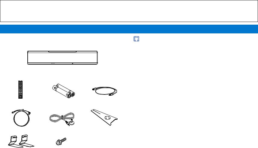
Supplied accessories
Before connecting, make sure you have received all of the following items.
YSP-5600
• The supplied optical cable may not be needed depending upon connections.
The unit
Supplied accessories |
|
|
Remote control |
Batteries |
Optical cable |
|
(AAA, R03, UM-4) (x2) |
(1.5 m (4.9 ft))1 |
Power cable (2 m (6.6 ft))2 IntelliBeam microphone Cardboard microphone stand (6 m (19.7 ft))
Stands (x2) |
Screws (For the stands; x2) |
• Owner’s Manual CD-ROM • Quick Reference Guide • MusicCast Setup Guide
1China model only: Instead of the optical cable, a digital coaxial audio cable is supplied.
2The shape of the power cable plug varies depending on where the unit was purchased.
FEATURES Supplied accessories |
En 6 |
|
|

Preparing remote control
Before installing batteries or using the remote control, be sure to read battery and remote control precautions in “Quick Reference Guide” (separate booklet).
|
Installing the batteries |
|
Operation range |
Battery × 2
(AAA, R03, UM-4)
Press down on the arrow and slide the cover in the direction in which it points.
Within 6 m (20 ft)
Slide the cover back to close it.
FEATURES Supplied accessories |
En 7 |
|
|
Controls and functions
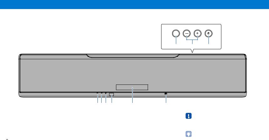
 The unit (front, top)
CONNECT VOLUME
INPUT
7 8 9
STATUS |
INTELLIBEAM MIC |
123 4 5 6
1 STATUS indicator
Lights to show the system condition. Glows green: Power on
Glows red: Power off (when the HDMI control or network standby is activated)
Turns off: Power off
2  (Wi-Fi) indicator
Shows the status of wireless network connection (p. 51).
3  (Bluetooth) indicator
Shows the status of Bluetooth connection (p. 45, 48).
6 INTELLIBEAM MIC jack
For connecting the supplied IntelliBeam microphone (p. 30).
7 INPUT/CONNECT key
INPUT key
Select an audio input source.
CONNECT key
Use to control the unit using the dedicated MusicCast CONTROLLER app for mobile devices. See the MusicCast Setup Guide for details.
•When the unit is turned off, this unit consumes a small amount of power in order to search for HDMI signals or to receive signals from a network device.
•The front panel display turns on for 3 seconds only when the unit is operated.
•“Dimmer” can adjust the brightness of the front panel display and indicators in the setup menu (p. 77).
4 Remote control sensor
Receives infrared signals from the remote control (p. 10).
5 Front panel display
Displays the unit’s settings, such as the name of an audio input source or surround mode (p. 43). The setting values are also displayed.
8VOLUME (+/-) keys
Adjust the volume of the unit (p. 36).
9z key
Turn on/off the unit.
FEATURES Controls and functions |
En 8 |
|
|

 The unit (rear)
• So that the HDMI and NETWORK jacks may be easily located, the illustration of the rear of the unit used in this manual shows their respective positions with the labels used on the unit itself.
1 2 |
3 |
|
4 |
|
5 |
|
6 |
7 |
IN 1 |
|
|
|
|
(HDCP2.2) |
|||||||
|
|
|
|
|
|
|
|
|
UPDATE ONLY |
IN 2 |
|
|
|
|
|
|
|
|
|
|
|
SYSTEM |
SUBWOOFER |
R |
L |
AUX2 |
TV |
OPTICAL |
IR-IN |
IR-OUT |
|
RS-232C |
CONNECTOR |
OUT |
AUX1 |
|
|
|
|
|
|
|
|
|
|
|
|
|
|
|
|
|
|
IN 3 |
|
|
|
|
|
|
|
|
|
IN 4 |
|
|
|
|
|
|
|
|
|
HDMI |
|
|
|
|
|
IN 1 |
|
|
|
|
|
|
|
|
|
(HDCP2.2) |
|
|
|
|
|
|
|
|
|
|
|
|
|
OUT |
|
|
|
|
|
|
|
|
|
(ARC) |
|
|
|
|
|
IN 2 |
|
|
|
|
|
|
|
|
|
IN 3 |
|
|
|
|
|
|
|
|
|
IN 4 |
|
|
|
|
|
|
|
|
|
HDMI |
|
|
|
|
|
|
|
|
|
OUT |
|
|
|
|
|
|
|
|
|
(ARC) |
|
|
|
|
AC IN |
|
|
|
|
|
|
|
UPDATE ONLY |
NETWORK |
SYSTEM |
SUBWOOFER |
R |
L |
AUX2 |
TV |
OPTICAL |
IR-IN |
IR-OUT |
RS-232C |
CONNECTOR |
OUT |
|
AUX1 |
|
|
|
|
|
|
a
8
0
9
NETWORK
1 SYSTEM CONNECTOR jack
Connect to a Yamaha subwoofer so that the subwoofer functions according to the unit’ power on and off (p. 25).
2 SUBWOOFER OUT jack
For connecting to the subwoofer using a wired connection (p. 25).
3 AUX1 analog input jacks
For connecting to a playback device equipped with the analog audio output jacks (p. 24).
4 AUX2 digital coaxial input jack
For connecting to a playback device equipped with a digital coaxial audio output jack (p. 24).
5 TV and OPTICAL jacks
For connecting to a playback device equipped with an digital optical audio output jack (p. 22, 23).
6 IR-IN, IR-OUT, and RS-232C jacks
They are control expansion jacks for commercial use only.
7 UPDATE ONLY jack
Use to update this unit’s firmware (p. 87).
8 HDMI IN 1–4 jacks
For connecting an HDMI-compatible playback device such as a BD/DVD player, a satellite and cable TV tuner, and a game console (p. 23).
9 HDMI OUT (ARC) jack
For connecting to an HDMI-compatible TV and outputting video/audio signals (p. 22).
0 NETWORK jack
For connecting to a network with a network cable (p. 51).
A AC IN jack
Connect the supplied power cable (p. 26).
FEATURES Controls and functions |
En 9 |
|
|

 Remote control
|
Infrared signal transmitter |
||
1 |
|
|
d |
|
|
|
e |
2 |
|
|
|
3 |
|
|
|
|
|
|
f |
4 |
|
|
g |
5 |
|
|
|
6 |
|
|
h |
7 |
|
|
|
8 |
|
|
i |
9 |
|
|
|
0 |
|
|
j |
a |
|
|
k |
b |
|
|
l |
c |
|
|
m |
1 ECO key
Turn the Eco function on or off (p. 43).
2 Input selector keys, NET key
Input selector keys
Select an audio input source to be played back (p. 36).
NET key
Select an audio input via a network (p. 49). Each time the key is pressed, the input source is selected as follows:
SERVER NET RADIO AirPlay Streaming music service (if available) MusicCast Link SERVER …
3 SYSTEM MEMORY keys
Save IntelliBeam measurements, speaker volume, and other settings (p. 44).
4SUB (+/-) key
Adjust the volume of the subwoofer (p. 36).
5MUTE (  ) key
) key
Mute the sound (p. 36).
6SETUP (  ) key
) key
Display the setup menu (p. 66).
7S/T/W/X keys, ENTER key
Change the setting (p. 66).
8RETURN (  ) key
) key
Return to the previous menu screen.
9CINEMA DSP program keys
When playback is in surround playback mode, select the CINEMA DSP programs (p. 38).
0 SURROUND key
Switch to surround playback mode (p. 38).
A 3D SURROUND key
Switch to 3D surround playback mode (p. 37).
B CLEAR VOICE key
Turn the CLEAR VOICE function on or off (p. 41).
C ENHANCER key
Turn Compressed Music Enhancer to on or off (p. 41).
D z key
Turn on/off the unit (p. 36).
E NET RADIO (1–3) keys
Register and play streaming services such as Internet radio stations via the unit (p. 61).
F DIALOG LIFT key
Use the Dialog Lift function to adjust the height from which dialog is heard (p. 41).
GVOL (+/-) key
Adjust the volume of the unit (p. 36).
HOPTION ( ) key
Display the option menu for each input source (p. 83).
IINFO (  ) key
) key
Switch the information display on the front panel (p. 43).
JSTEREO key
Switch to stereo playback mode (p. 40).
KTARGET key
Switch to target playback mode (p. 40).
LWPS/CH LEVEL key
WPS key
Use the key when connecting to a wireless router (access point) that supports the WPS (push button) feature (p. 53).
CH LEVEL key
Adjust the volume balance during playback (p. 42).
MCONNECT key
Use to control the unit using the dedicated MusicCast CONTROLLER app for mobile devices. See the MusicCast Setup Guide for details.
FEATURES Controls and functions |
En 10 |
|
|
PREPARATIONS
General setup procedure
1Installation (p. 12)
2Connecting a TV (p. 22)
3Connecting playback devices (p. 23)
4Other connections (p. 25)
5Connecting the power cable (p. 26)
6Initial settings (p. 27)
Position the unit to achieve the optimal surround sound effects. The unit can also be mounted on a wall.
Connect a TV to the unit.
Connect video devices (such as BD/DVD players) to the unit.
Connect a subwoofer.
Use a network cable to connect the unit to a router in preparation for wired network connection.
After all the connections are complete, plug in the power cable.
Perform initial setup, such as adjusting surround sound effects, before attempting playback.
This completes all the preparations. Enjoy playing movies, music and other content with the unit!
• See “NETWORKS” (p. 49) for information regarding network connection and audio playback via a network.
PREPARATIONS General setup procedure |
En 11 |
|
|
1 2 3 4 5 6
aInstallation
This unit reflects sound beams off of walls and a ceiling to create the surround sound effect. The position of this unit in relation to the listening position, walls, and a ceiling is important to achieving the desired surround sound effects. Refer to pages 12 to 16 when installing the unit. When installing this unit on a rack behind which there is limited space, for example, it may be easier to connect external devices to this unit first. This will depend upon the installation location. See pages 22 to 25 for information regarding the connection of external devices.
Notes
•Be sure to install this unit on a large, stable stand where it does not fall subject to vibrations, such as from an earthquake, and where it is out of the reach of children.
•There is a built-in antenna on the top of the unit. Do not install it on a metal rack, and do not stack metal items on top of the unit.
•The unit’s speakers are not magnetically shielded. Do not install hard disk drives or similar devices near the unit.
•Do not stack the unit directly on top of other playback devices, or vice versa. Heat and vibrations may result in damage or malfunction.
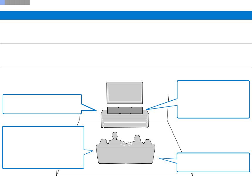
 Recommended place for installation
•Install the unit in the center of the left and right walls.
•This unit can be mounted on a wall (p. 17).
•The listening position (such as sofa, etc.) should be located at the front of the unit.
•The distance between the listening position and the unit should be more than 1.8 m (6 ft).
•Set the listening position as far from the back wall as possible (the optimal listening position is halfway between the unit and the back wall, or slightly closer to the back wall).
•Be sure that the unit installed with at least 5 cm of empty space above and below it.
•Leaving as much space as possible in a
diagonal direction in front of, and above, the unit when installing it.1
•Attach the supplied stands to the unit if it will be installed on a rack 2 (p. 16).
1Height channel audio is output in a diagonal direction upward and forward from the unit (p. 5).
2Depending upon the rack, table-top stand, or floor stand used, the stands may not be necessary.
• To achieve desired surround sound effects, be  sure that obstacles such as furniture may not
obstruct the path of sound beams (p. 13).
PREPARATIONS aInstallation |
En 12 |
|
|
1 2 3 4 5 6
 Example for installing the unit
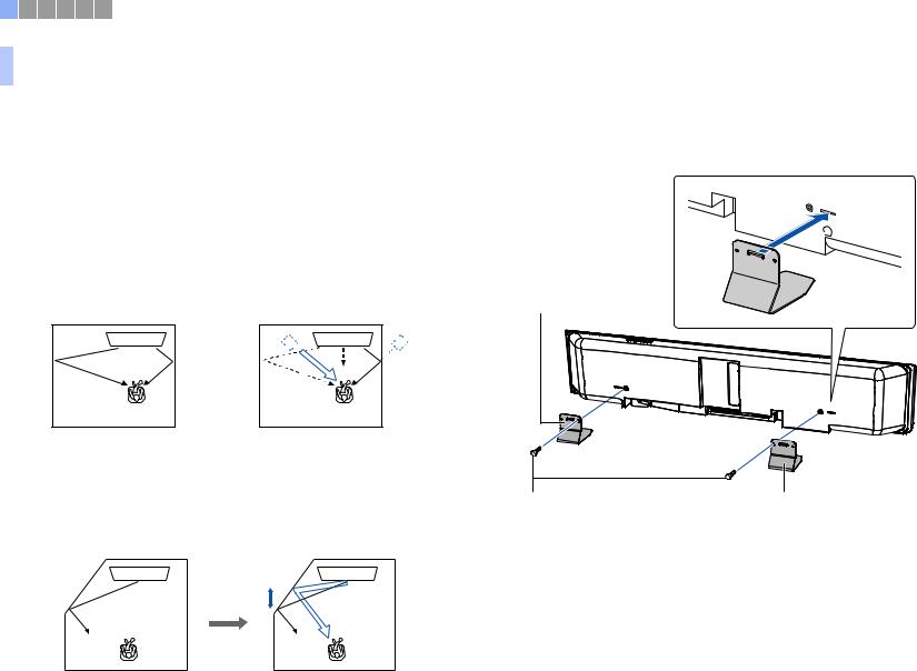
This unit outputs sound beam as shown in the illustrations below. Install this unit where there are no obstacles such as furniture obstructing the path of sound beams. Otherwise, the desired surround sound effects may not be achieved.
If the unit is installed so that it is parallel to a wall, install it as close to the exact center of the wall as possible.
If the unit is installed in a corner of a room, position it at a 40–50° angle to the adjacent walls.
Parallel installation: Viewed from above |
|
|
Viewed from the side |
||||||||
|
|
|
|
|
|
|
|
Objects, |
|
|
|
|
|
|
|
|
|
|
|
|
|
Sound beams |
|
|
|
|
|
|
|
|
|
such as |
|
|
are reflected off |
|
|
|
|
|
|
||||||
|
|
|
|
|
|
|
|
furniture |
|
|
the ceiling |
|
|
|
|
|
|
|
|
|
|
|
|
|
|
|
|
|
|
|
|
|
|
|
|
|
|
|
|
|
|
|
|
|
|
|
|
|
|
|
|
|
|
|
|
|
|
|
|
|
|
|
|
|
|
|
|
|
|
|
|
Sound beam output varies depending upon the 3D surround/Surround setting (p. 37, 38) and the channel output setting (p. 72). The illustration above shows the path of sound beams when 3D surround is enabled and “Front” in the Channel Out setting is set to “Beam”.
Corner installation: Viewed from above |
Viewed from the side |
40° to 50° |
Objects, such as furniture
Sound beams are reflected off the ceiling
The illustrations above show the path of sound beams when 3D surround is enabled (p. 37) and “Front” in the Channel Out setting is set to “Stereo”. (p. 72).
Parallel installation
Install this unit as close to the exact center of the wall as possible.
•If the unit cannot be installed evenly between the left and right walls, sound beams can be adjusted to achieve natural surround sound effects (p. 16).
Ideal installation condition
Install this unit as close to the exact front of your normal listening position as possible. The distance between listening position and the unit should be more than 1.8 m (6 ft).
More than 1.8 m (6 ft)
More than 1.8 m (6 ft)
PREPARATIONS aInstallation |
En 13 |
|
|

1 2 3 4 5 6
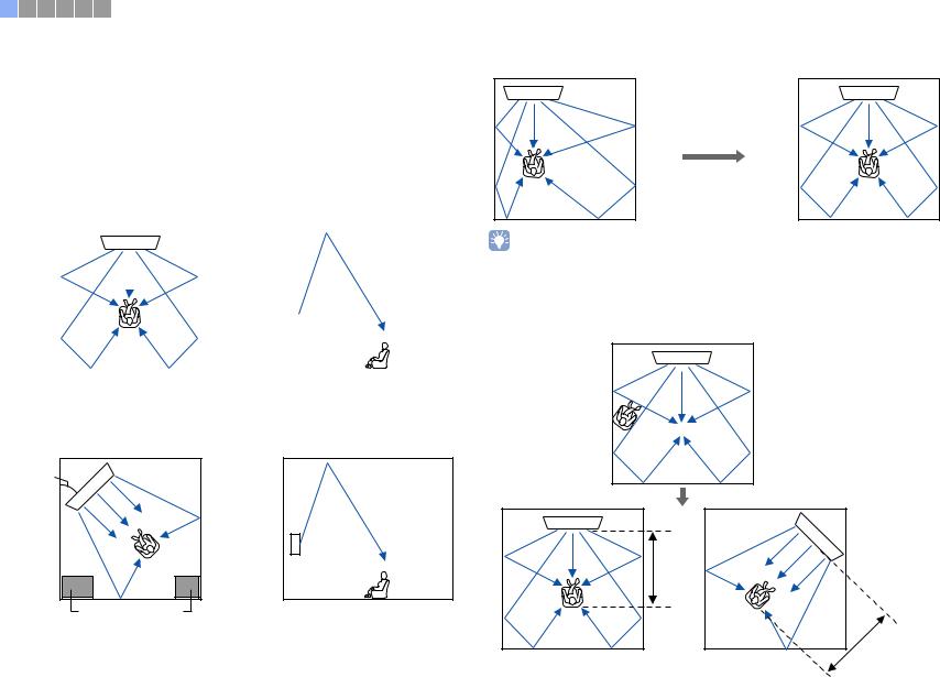
Installing in a non-square room
Install this unit so that the sound beams can be reflected off the walls.
Irregularly shaped rooms with solid walls on all sides
Irregularly shaped rooms that are open to a hallway on one side
•If this unit cannot be repositioned, or the listening position cannot be changed, the optional YRB-100 sound reflection board may be installed for a better surround sound experience (p. 99).
PREPARATIONS aInstallation |
En 14 |
|
|

1 2 3 4 5 6
Example for installing the unit in living room
•The legs on a table are not considered obstacles as sound beams normally pass through them. A cupboard installed facing the wall reflects sounds.
•As the heavy curtains absorb sounds, the sound features of the listening room is different from the case with the curtain opened and the case with the curtain closed. Using saving settings function enables to save the best settings for each case of listening room (p. 44).
Objects, such as furniture
 Unrecommended listening environments
This unit creates surround sound by reflecting projected sound beams off the walls and the ceiling of your listening room. The surround sound effects produced by this unit may not be sufficient when this unit is installed in the following locations.
•Rooms with walls inadequate for reflecting sound beams
•Rooms with acoustically absorbent walls and ceiling
•Rooms with measurements outside the following range: W (3 to 7 m (10 to 23 ft)) × H (2 to 3.5 m (7 to 11.5 ft)) × D (3 to 7 m (10 to 23 ft))
•Rooms where objects such as furniture are likely to obstruct the path of sound beams
•Rooms with less than 1.8 m (6 ft) from the listening position to this unit
•Rooms where the listening position is close to the walls
•Rooms where the listening position is not in front of this unit
•Rooms with a complex shape, such as a slanted ceiling (ceiling lights do not obstruct sound beams)
Enjoying surround effects regardless of conditions (My Surround)
The My Surround function creates rich surround sound effects in rooms with less than optimal surround sound conditions. See “Channel Out” (p. 72) for more information.
PREPARATIONS aInstallation |
En 15 |
|
|
1 2 3 4 5 6
Adjusting sound beams to achieve optimal surround sound effects
This unit’s AUTO SETUP (p. 29) can be used to automatically adjust sound beams to achieve the optimal surround playback environment according to the listening room setup. In addition to using AUTO SETUP, sound beams can be adjusted manually to achieve surround sound effects best suited to the listening room setup when the unit is installed as described below.
Installing the unit near a corner of the room
When installing the unit near a corner of the room as shown in the illustration below, front channel sound may seem to come from an unnatural direction if beam settings are configured using AUTO SETUP.
Should this occur, adjust the left and right front channels using “Image Location” (p. 71) in the setup menu to achieve more natural sound.
When left front channel sound is |
|
unnatural |
Left front channel adjusted |
Installing the unit in an irregularly shaped room
When the unit is installed in a room that is not rectangular, sound beams may not be properly reflected off the walls as shown in the illustration below.
Should this occur, perform AUTO SETUP, and then adjust the angle of beam from the channel from which sound is not properly heard using “Horizontal Angle” (p. 69) in the setup menu to achieve even distribution of sound.
 Installing the stands
Install the stands (supplied) on the bottom of the unit. Align and insert the protrusion on the stands into the holes on the rear panel of the unit as shown in the illustration, and then tighten the screws (supplied) to lock the stands in place. The stands need not be installed when the unit is mounted on a wall using the optional Wall Mount Bracket SPM-K30.
Stand (supplied)
Screws (supplied) |
Stand (supplied) |
PREPARATIONS aInstallation |
En 16 |
|
|
1 2 3 4 5 6
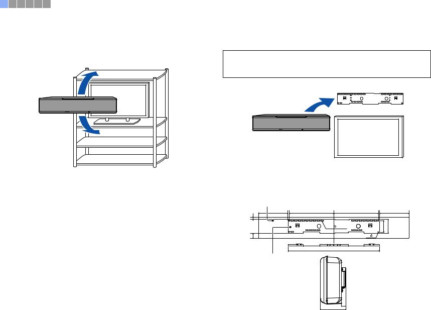
 Installing the unit on a rack
The unit can be installed on a shelf, either above or below the TV, on a third-party rack.
The rack and the shelf on which the unit is placed should be large enough to allow adequate ventilation around the unit and the rack should be sturdy enough to support the weight of both the unit and the TV.
TV |
 Mounting the unit on a wall
The unit can be mounted on a wall using the optional Wall Mount Bracket (such as SPM-K30).
Notes
Instructions for mounting the unit are not included in the Installation Manual supplied with the SPM-K30. Always follow the instructions provided in this Owner’s Manual.
Wall Mount Bracket (SPM-K30)
YSP-5600
TV
Dimensions when the unit is mounted using the SPM-K30
Be sure to refer to the dimensions below and leave adequate space for ventilation around the unit.
YSP-5600 |
(mm) |
188 |
355 |
355 |
182 |
26.5 |
|
|
|
24- |
7x22 |
92 |
114 |
|
|
||
71.5 |
|
4- 7 |
|
730
SPM-K30 (optional)
112.4 |
19.4 |
|
PREPARATIONS aInstallation |
En 17 |
|
|

1 2 3 4 5 6
•The SPM-K30 may not be available in some countries or regions.
•When the unit will be installed using the wall mount bracket, all installation work should be performed by a qualified contractor or experienced retail staff. The customer should not attempt to install the unit themselves. Improper installation may cause the unit to fall, resulting in personal injury.
•Installation must be secure enough to bear the weight of the unit and the wall mount bracket, possibly for years to come, and must also be secure enough to withstand vibrations, such as those caused by earthquakes. Improper installation may cause the unit to fall, resulting in personal injury.
•To prevent the unit from falling, attach it to a wall constructed of drywall (plasterboard).
•Be sure to use screws capable of supporting the weight of the wall mount bracket and the unit (with steps 2 and 7). Using items other than the specified screws, such as shorter screws, nails, or double-sided tape, may cause the unit to fall, resulting in personal injury.
•To ensure safety, all screws must be tightened securely. Loose screws may cause the unit to fall, resulting in personal injury.
•Be sure to leave adequate space for ventilation around the unit so that heat generated by the unit is allowed to dissipate. Failure to provide adequate space around the unit may cause the unit to overheat internally, resulting in a fire.
•Do not lean on the unit or apply excessive force to the top of the unit. Doing so may cause the unit to fall, resulting in personal injury.
•Fix cables in place so that they will not become loose. If a foot or hand becomes accidentally entangled in, or catches on, a loose cable, the unit may fall, resulting in personal injury.
•Once the unit is installed, safety checks should be conducted on a regular basis. When the unit is used over an extended period of time, screws can become loose and the installation can weaken due to the passage of time, vibrations, etc.
•Note that Yamaha cannot be held liable for accidents, including falling of the unit, resulting from improper installation of the unit, or for damage to walls.
1Assemble the large wall mount bracket.
Align the screw holes A on the left bracket with those on the right bracket, and tighten the screws.
Large wall mount bracket (left)
Screw (M4; supplied with the SPM-K30)
 Large wall mount bracket (right)
730 mm
2Attach the wall mount bracket assembled in step 1 to the wall.
In order to secure the unit to the wall, the bracket must first be attached to the wall in a manner suited to the structure and quality of the wall.
4mm self-tapping screws (available from third-party manufacturers) Washers (available from third-party manufacturers)
Installing into a |
Installing directly |
||||||||||
dray wall |
into a wall, etc. |
||||||||||
25 mm or more |
25 mm or more |
||||||||||
|
|
|
|
|
|
|
|
|
|
|
|
|
|
|
|
|
|
|
|
|
|
|
|
|
|
|
|
|
|
|
|
|
|
|
|
|
|
|
|
|
|
|
|
|
|
|
|
|
|
|
|
|
|
|
|
|
|
|
|
Beam, etc. Dry wall
•In order to secure the unit to the wall, drive six (or more) tapping screws from the outside through the holes in the wall mount bracket.
PREPARATIONS aInstallation |
En 18 |
|
|

1 2 3 4 5 6
3 Attach the small wall mount brackets to the unit.
Screws (M4; supplied with the SPM-K30)
Small wall mount bracket (Type B)
Screw hole (left side)
Screws(M4; |
supplied with |
the SPM-K30) |
Small wall mount bracket (Type B)
Screw hole (right side)
4Attach the safety wires to the small wall mount brackets (left and right) to prevent the unit from falling.
Safety wire |
Slip one end through |
the loop at the other end |


 Slip the safety wire
  between the bracket and the projector
PREPARATIONS aInstallation |
En 19 |
|
|

1 2 3 4 5 6
5Fit the mounting guide hooks of the small wall mount brackets attached to the unit into the holes on the left and right sides of the large wall mount bracket and then slide the unit to the right.
Fit the hook into the hole.
Slide the unit to the right.
6Align the holes in the large wall mount bracket with the holes in the bottom of the small wall mount brackets, and then use two of the screws (M6; supplied with the SPM-K30) to secure the unit.
•Hold the unit tight with both hands when attaching or removing the unit to or from the wall. Holding the unit loosely could cause the unit to fall, resulting in personal injury.
Bottom side of the unit
Screws
(M6; supplied with the SPM-K30)
PREPARATIONS aInstallation |
En 20 |
|
|
1 2 3 4 5 6
7Pass the screws through the loops of the safety wires and then tighten the screws to secure the safety wires to the wall.
|
|
Washer (supplied |
|
|
|
with the SPM-K30) |
|
Secure the safety |
Screw (available |
|
|
wire to the wall. |
Secure the |
||
from third-party |
|||
|
manufactures) |
safety wire to |
|
|
|
the wall. |
•Attach the safety wires tight.
•Keep the two other washers for future use.
PREPARATIONS aInstallation |
En 21 |
|
|

1 2 3 4 5 6
bConnecting a TV
Connect a TV to the unit so that video input to the unit can be output to the TV. You can also enjoy playback of TV audio on the unit.
•Use a 19-pin HDMI cable with the HDMI logo printed on it. A cable with a maximum length of 5 m is recommended to prevent degradation of signal quality.
•For playback of 3D and 4K video content, use a high-speed HDMI cable.
•This unit supports HDCP version 2.2, a copy protection technology. To enjoy playback of 4K video, connect the unit to the HDMI IN jack (one compatible with HDCP 2.2) on an HDCP 2.2-compliant TV.
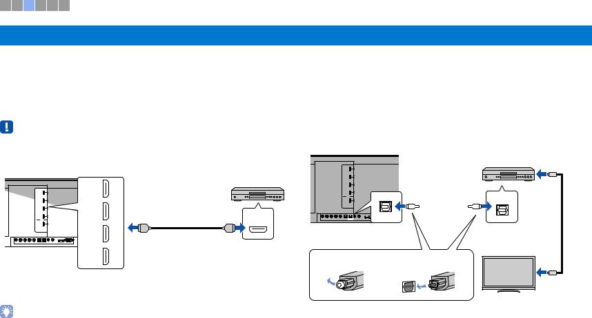
 TVs that support Audio Return Channel (ARC)
Connect the TV to the unit with an HDMI cable (not supplied).
HDMI OUT (ARC) jack |
ARC-compatible HDMI input |
|
|
|
HDMI |
OUT |
HDMI |
(ARC) |
(ARC) |
HDMI |
|
|
|
|
The unit (rear) |
TV |
|
When connecting a TV that supports Audio Return Channel (ARC), enable the HDMI control function (p. 76).
What is Audio Return Channel (ARC)?
In order for the unit to play audio from a TV, the TV must usually be connected to the unit via an audio cable as well as an HDMI cable. If, however, the TV supports Audio Return Channel (ARC), TV audio signals can be input to the unit via the HDMI cable that outputs video signals from the unit to the TV.
• Use an ARC-compatible HDMI cable.
 TVs that do not support Audio Return Channel (ARC)
Connect the TV to the unit with an HDMI cable (not supplied) and an optical cable.
|
HDMI OUT (ARC) jack |
|
HDMI input |
|
|
|
|
|
HDMI |
|
OUT |
HDMI |
HDMI |
|
|
(ARC) |
|
|
|
|
|
|
OPTICAL |
|
|
|
O |
O |
|
|
TV |
|
|
|
The unit (rear) |
TV jack |
Audio output |
TV |
|
|
|
|
(digital optical) |
|
1. Remove the cap |
2. Check the direction of |
|
||
|
|
the plug |
|
|
•If the TV has no optical jack
Connect the audio output jack on the TV to the AUX1 (analog) input jack or AUX2 (digital coaxial) jack on the unit, and set “TV Input” in the setup menu to “Analog [AUX 1]” or “Coaxial [AUX 2]” accordingly (p. 76). TV audio can be played through the unit by pressing the TV key on the remote control.
PREPARATIONS bConnecting a TV |
En 22 |
|
|
1 2 3 4 5 6
cConnecting playback devices
Connect video devices such as BD/DVD players, set-top boxes (STBs) and game consoles to the unit. Depending on the video/audio output jacks available on your video device, choose one of the following connections. We recommend using an HDMI connection if the video device has an HDMI output jack.
 HDMI connection
Connect a video device to the unit with an HDMI cable (not supplied).
•This unit supports HDCP version 2.2, a copy protection technology. When using an HDCP 2.2-compliant playback device, such as a set-top box, connect it to the unit via the HDMI IN 1 jack. When connecting playback devices that do not support HDCP version 2.2, any HDMI IN jack (1–4) may be used.
The unit (rear)
HDMI IN 1–4 jacks |
Video device |
IN 1 |
|
(HDCP2.2) |
|
IN 2 |
|
|
HDMI |
HDMI |
HDMI |
IN 3 |
|
|
HDMI output |
IN 4 |
|
The audio/video played on the video device will be output though the unit by switching input to HDMI 1–4 using the HDMI 1–4 key on the remote control.
•Once the HDMI control function has been activated (p. 34), video and audio content from playback devices can be output from the TV even when this unit is off (HDMI signal pass-through).
•Use a 19-pin HDMI cable with the HDMI logo printed on it. A cable with a maximum length of 5 m is recommended to prevent degradation of signal quality.
•For playback of 3D and 4K video content, use a high-speed HDMI cable.
•When audio from the video device cannot be output via the HDMI jack, use an optical cable to connect the video device to the unit via the digital optical output jack on the video device and the OPTICAL jack on the unit. If the video device is connected to the unit in this way, change “Audio Assign” to “Optical” in option menu (p. 84).
 Optical connection
Connect a video device to this unit via the optical cable. Next, connect the video device’s video output to the TV’s video input.
The unit (rear)
O 


 O
O


 OPTICAL
Video device |
To video output |
|
jack |
||
|
||
OPTICAL |
|
OPTICAL jack |
Audio output |
||
(digital optical) |
|||
|
|
||
1. Remove the cap |
2. Check the direction of |
|
|
|
the plug |
|
|
|
|
To video input |
|
|
|
jack |
|
|
|
TV |
|
The audio played on the video device will be output though the unit by switching input to OPTICAL using the OPTICAL key on the remote control.
PREPARATIONS cConnecting playback devices |
En 23 |
|
|
1 2 3 4 5 6
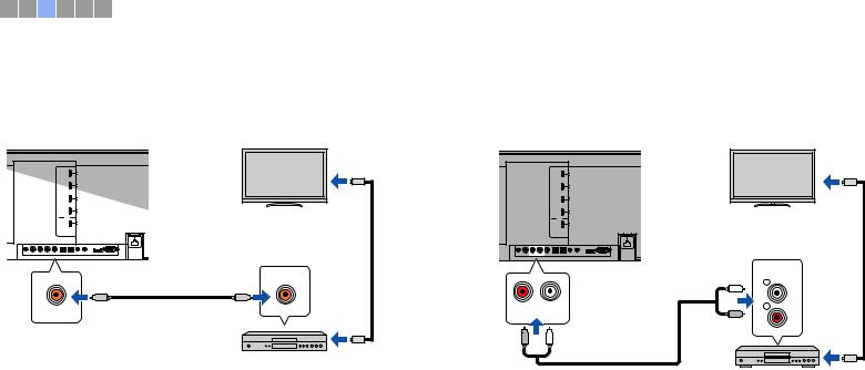
 Coaxial connection
Connect a video device to this unit via a digital coaxial cable. Next, connect the video device’s video output to the TV’s video input.
The unit (rear) |
TV |
To video output jack
Audio output (digital coaxial)
COAXIAL
C |
C |
AUX2
AUX2 (digital
coaxial) jack

 To video input jack Video device
The audio played on the video device will be output though the unit by switching input to AUX2 using the AUX 2 key on the remote control.
 Analog connection
Connect a video device to this unit via a stereo cable (not supplied). Next, connect the video device’s video output to the TV’s video input.
The unit (rear) |
TV |
To video output jack
|
|
|
Audio output |
|
|
|
(analog) |
|
|
AUX1 (analog) jacks |
AUDIO |
|
|
L |
|
|
|
|
|
|
|
|
L |
R |
L |
|
R |
AUX1 |
|
|
R |
R |
L |
|
|
Video device |
To video input jack |
|
The audio played on the video device will be output though the unit by switching input to AUX1 using the AUX 1 key on the remote control.
PREPARATIONS cConnecting playback devices |
En 24 |
|
|
1 2 3 4 5 6
dOther connections
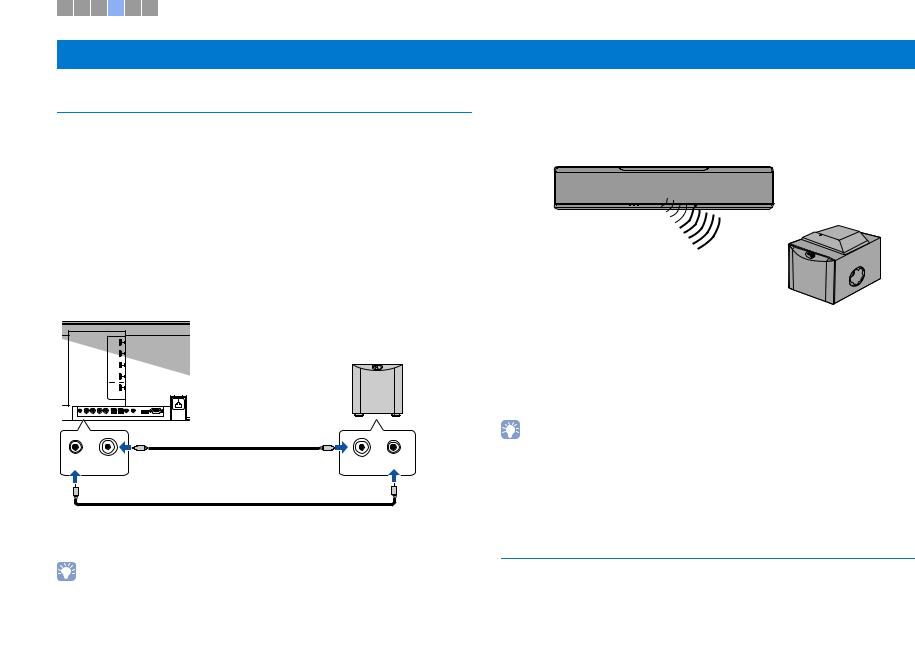
Connecting a subwoofer
A subwoofer can be connected to the unit for use with the unit. There are two ways to connect a subwoofer to the unit: use a third-party RCA monaural cable, or use the optional wireless subwoofer kit SWK-W16 to connect via a wireless connection.
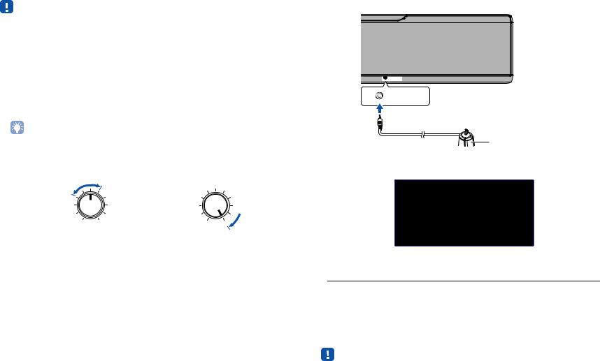
 Using the optional wireless subwoofer kit SWK-W16
The optional wireless subwoofer kit SWK-W16 enables wireless connection of a subwoofer to the unit.
 Connecting a subwoofer via cable
Use a third-party RCA monaural cable to connect the subwoofer to the unit via the monaural input jack on the subwoofer and the SUBWOOFER OUT jack on the unit.
When connecting a Yamaha subwoofer equipped with a system connector, connect a system control cable (or third-party 3.5mm monaural mini plug cable) to the SYSTEM CONNECTOR on the unit. This connection is required to turn the unit and subwoofer on and off at the same time.
The unit (rear)
Subwoofer
SYSTEM |
SUBWOOFER |
INPUT |
SYSTEM |
CONNECTOR |
OUT |
|
CONNECTOR |
When the unit is connected to the subwoofer via the cable, set the subwoofer output to “Wired” in the setup menu (p. 73)
• See documentation supplied with the subwoofer for more information.
SWK-W16
Subwoofer
When using the wireless subwoofer kit, set subwoofer output to “Front/Wireless” (default setting) in the setup menu (p. 73).
The unit and the wireless subwoofer kit are automatically connected via wireless connection when the unit is turned on, or when subwoofer output in the setup menu is set to “Front/Wireless”.
•See “Troubleshooting” (p. 90) if the indicator on the wireless subwoofer kit does not glow green.
•See the Owner’s Manual supplied with the wireless subwoofer kit SWK-W16 for information regarding SWK-W16 and subwoofer connection.
•The wireless subwoofer kit SWK-W16 cannot be used while the subwoofer is connected to the unit via cables.
•The SWK-W16 may not be available in some countries or regions.
Wired network connections
For a wired connection, connect one end of the network cable to the NETWORK jack on the rear panel of the unit and the other end to a router. For details, refer to “NETWORKS” (p. 49).
PREPARATIONS dOther connections |
En 25 |
|
|

1 2 3 4 5 6
eConnecting the power cable
After all the connections are complete, plug in the power cable.
The unit (rear)
To an AC wall outlet
PREPARATIONS eConnecting the power cable |
En 26 |
|
|

1 2 3 4 5 6
z
OPTION ( |
) |
SETUP ( |
) |
fInitial settings
Displaying the menu screen on the TV
Visual operation of this unit is possible by displaying its menu screen on the TV.
Turn on the unit and the TV, and then use the input button on the TV’s remote control to switch input so that video input from this unit is displayed.
When this unit and the TV are connected as shown below, select “HDMI 1” using the TV’s remote control.
TV remote control (example)
 Switch input sources
The unit (rear)
TV
The menu display
The menu is displayed on the TV screen when the SETUP ( ) key or OPTION ( ) key is pressed. When the TV is receiving HDMI signals, the menu is superimposed over video content. Press the
SETUP ( ) key twice or OPTION ( |
) key a second time to cancel |
|||
menu display. |
|
|
|
|
|
|
|
|
|
|
Setup Menu |
|
|
|
|
|
IntelliBeam |
|
|
|
Beam |
|
||
|
Sound |
Horizontal Angle |
|
|
|
HDMI |
Vertical Angle |
|
|
|
Display |
Beam |
Travel Length |
|
|
Information |
Focal |
Length |
|
|
|
Image |
Location |
|
|
|
Channel Out |
|
|
|
|
Subwoofer |
|
|
|
|
|
|
|
•The setup menu (p. 66) can only be displayed on a TV screen. It cannot be shown in the front panel display.
|
HDMI INPUT |
|
1 |
2 |
3 |
OUT (ARC)
HDMI
HDMI
PREPARATIONS fInitial settings |
En 27 |
|
|

Initial screen display
When the unit is turned on for the first time after purchase, the screen below will be displayed. (“ViewScreen” is shown in the front panel display.)
S h a r e W i - F i S e t t i n g s
Y o u c a n |
s h a r e t h e w i r e l e s s |
||
( W i - F i ) |
s e t t i n g s o f |
t h e |
|
n e t w o r k |
w i t h S o u n d P r o j e c t o r |
||
u s i n g a |
d e v i c e w i t h |
i O S 7 o r |
|
l a t e r . |
|
|
|
[ E N T E R ] : S t a r t |
|
||
[ R E T U R N ] : C a n c e l |
|
||
|
[ |
] : O S D L a n g u a g e |
|
While this screen is displayed, an iOS device (such as an iPhone) can be used to easily connect the unit to a wireless network. See the Quick Reference Guide for more information.
If you will not use an iOS device to connect to a wireless network, press the RETURN (  ) key.
•You can use this function to connect to a wireless network at any time by selecting “Share Wi-Fi Settings (iOS)” from the setup menu. However, be aware that if a different wireless network, or a Bluetooth device, has already been configured, doing so will erase any previous settings.
•This screen will not be displayed if the unit is connected to a router via its NETWORK jack (wired connection).
•Be aware that if the IntelliBeam microphone is connected while the screen shown above is displayed (p. 29), setup will be canceled, and the screen will switch to the auto measurement screen.
Selecting the language for menu display
1 Turn the unit and TV on.
2 Switch the TV’s input to display video input from this unit (p. 27).
3Press and hold the SETUP ( ) key until the “OSD Language” menu appears on the TV.
OSD Language
ENGLISH
DEUTSCH
FRANÇAIS
ESPAÑOL
ITALIANO
NEDERLANDS
Р У С С К И Й
SVENSKA TÜRK
When the menu is not displayed
•Confirm the following cases.
–The HDMI input jack of your TV and the HDMI OUT (ARC) jack of the unit are connected.
–The input of your TV is set to “HDMI 1” (example).
4Use the S/T key to select the desired language and press the
ENTER key.
Settings

 , ENGLISH (default), DEUTSCH, FRANÇAIS, ESPAÑOL, ITALIANO, NEDERLANDS,
РУССКИЙ, SVENSKA, TÜRK
5 Press the SETUP ( ) key to exit the setup menu.
PREPARATIONS fInitial settings |
En 28 |
|
|

Auto setup for appropriate surround effects (IntelliBeam)
First use the “IntelliBeam” function to adjust each channel so that this unit provides the optimal viewing and listening environment.
•The AUTO SETUP procedure may not be run successfully if this unit is installed in one of the rooms described in “Unrecommended listening environments” (p. 15).
•In order for this unit to provide the optimal listening environment, adjust each channel first using the “IntelliBeam” function. The My Surround function can be used to enjoy rich surround sound in these types of rooms as well. See “Channel Out” (p. 72) for more information.
•Do not connect the IntelliBeam microphone to an extension cable as doing so may result in an inaccurate sound optimization.
 Installing the IntelliBeam microphone
1 Place the IntelliBeam microphone at your normal listening position.
Assembling the supplied cardboard microphone stand
1 |
2 |
3 Fit in |
|
Remove |
|
Fit in
|
Place horizontally |
4 |
5 |
 Run through
•Use the supplied cardboard microphone stand or a tripod to place the IntelliBeam microphone at the same height as your ears would be when you are seated.
•Position the IntelliBeam microphone so that it is parallel with the floor.
IntelliBeam microphone
Center height of this unit
Cardboard microphone stand
1.8 m (6.0 ft) or more
Upper limit
Within 1 m (3.3 ft)
Within 1 m (3.3 ft)
Listening position
Lower limit
Center line
IntelliBeam microphone
Cardboard microphone stand
Make sure that there are no obstacles between the IntelliBeam microphone and the walls in your listening room as these objects obstruct the path of sound beams. However, any objects that are in contact with the walls will be regarded as a protruding part of the walls.
PREPARATIONS fInitial settings |
En 29 |
|
|
|
Using AUTO SETUP (IntelliBeam) |
3 Connect the IntelliBeam microphone to the INTELLIBEAM MIC jack |
|
||
|
|
of the unit. |
•Test tones output during measurement are loud. Perform AUTO SETUP when no children are around and there is no possibility of their entering the listening room, as their hearing may be impaired.
•If there are curtains in your listening room, we recommend following the procedure below.
1.Open the curtains to improve sound reflection.
2.Run “Beam optimize only” (p. 32).
3.Close the curtains.
4.Run “Sound optimize only” (p. 32).
•Make sure that your listening room is as quiet as possible. For accurate measurement, turn off air conditioner or other devices that make noises.
INTELLIBEAM MIC
 INTELLIBEAM MIC
1 Turn the unit and your TV on.
|
IntelliBeam microphone |
• When a subwoofer is connected to the unit, turn on the subwoofer, and set the volume and crossover |
Cardboard microphone stand |
frequency as shown below. |
|
Set the volume to half |
Set the crossover frequency to maximum |
VOLUME |
CROSSOVER |
|
HIGH CUT |
MIN MAX |
MIN MAX |
2 Switch TV input to display video input from this unit (p. 27).
The screen below is displayed after connecting IntelliBeam microphone to the unit.
|
A U T |
O |
S E T U |
P |
|
( P R E P A R A T I O N |
& |
C H E C K ) |
|||
P l e a s e |
c o n n e c t t h e |
M I C . |
|||
P l e a s e |
p l a c e |
t h e |
M I C a t l e a s t |
||
1 . 8 m / 6 f t a w a y |
f r o m |
S o u n d P r o - |
|||
j e c t o r . T h e M I C s h o u l d b e s e t
a t e a r l e v e l |
w h e n |
s e a t e d . |
|
M e a s u r e m e n t t a k e s |
a b o u t 3 m i n . |
||
A f t e r [ E N T E R ] |
i s |
p r e s s e d , |
|
p l e a s e l e a v e |
t h e |
r o o m . |
|
[ E N T E R ] : S t a r t |
[ R E T U R N ] : C a n c e l |
||
“AUTO SETUP” in the “IntelliBeam” menu can automatically adjust the following two settings.
Beam optimize |
This feature optimizes the beam angle so that the parameter best |
only |
matches your listening environment. |
|
|
Sound optimize |
This feature optimizes sound quality for each channel by measuring |
only |
the acoustic characteristics of the listening environment. |
|
|
“Beam optimize only” or “Sound optimize only” can be measured separately in the setup menu (p. 32).
•Follow the instructions below and then leave the room. If you remain in the room, you may obstruct the beam, or the microphone may pickup any sounds you make, possibly resulting in improper measurement.
PREPARATIONS fInitial settings |
En 30 |
|
|
Loading...