


YFM7FGPX
YFM7FGX
SERVICE
INFORMATION
3B4-28197-E1-SI
FOREWORD
This Service Information has been prepared to introduce new service and data for the YFM7FGPX/ YFM7FGX. For complete service information procedures it is necessary to use this Service Information together with the following manual.
YFM7FGPX/YFM7FGX SUPPLEMENTARY SERVICE MANUAL: 3B4-28197-E1
YFM7FGPW SERVICE INFORMATION: 3B4-28197-E0-SI
YFM7FGPX/YFM7FGX
SERVICE INFORMATION ©2007 by Yamaha Motor Co., Ltd.
First edition, March 2007 All rights reserved.
Any reproduction or unauthorized use without the written permission of Yamaha Motor Co., Ltd.
is expressly prohibited.
EBS00002
NOTICE
This manual was produced by the Yamaha Motor Company primarily for use by Yamaha dealers and their qualified mechanics. It is not possible to include all the knowledge of a mechanic in one manual, so it is assumed that anyone who uses this book to perform maintenance and repairs on Yamaha vehicle has a basic understanding of the mechanical ideas and the procedures of vehicle repair. Repairs attempted by anyone without this knowledge are likely to render the vehicle unsafe and unfit for use.
This model has been designed and manufactured to perform within certain specifications in regard to performance and emissions. Proper service with the correct tools is necessary to ensure that the vehicle will operate as designed. If there is any question about a service procedure, it is imperative that you contact a Yamaha dealer for any service information changes that apply to this model. This policy is intended to provide the customer with the most satisfaction from his vehicle and to conform to federal environmental quality objectives.
Yamaha Motor Company, Ltd. is continually striving to improve all its models. Modifications and significant changes in specifications or procedures will be forwarded to all authorized Yamaha dealers and will appear in future editions of this manual where applicable.
NOTE:
•This Service Manual contains information regarding periodic maintenance to the emission control system. Please read this material carefully.
•Designs and specifications are subject to change without notice.
EBS00003
IMPORTANT INFORMATION
Particularly important information is distinguished in this manual by the following notations.
 WARNING
CAUTION:
NOTE:
The Safety Alert Symbol means ATTENTION! BECOME ALERT! YOUR SAFETY IS INVOLVED!
Failure to follow WARNING instructions could result in severe injury or death to the vehicle operator, a bystander or a person checking or repairing the vehicle.
A CAUTION indicates special precautions that must be taken to avoid damage to the vehicle.
A NOTE provides key information to make procedures easier or clearer.

EBS00004
HOW TO USE THIS MANUAL
MANUAL ORGANIZATION
This manual consists of chapters for the main categories of subjects. (See “SYMBOLS”.)
1st title 1: This is the title of the chapter with its symbol in the upper right corner of each page. 2nd title 2: This title indicates the section of the chapter and only appears on the first page of each section. It is located in the upper left corner of the page.
3rd title 3: This title indicates a sub-section that is followed by step-by-step procedures accompanied by corresponding illustrations.
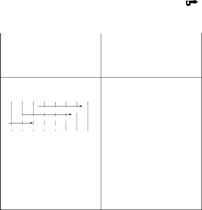
EXPLODED DIAGRAMS
To help identify parts and clarify procedure steps, there are exploded diagrams at the start of each removal and disassembly section.
1.An easy-to-see exploded diagram 4 is provided for removal and disassembly jobs.
2.Numbers 5 are given in the order of the jobs in the exploded diagram. A number that is enclosed by a circle indicates a disassembly step.
3.An explanation of jobs and notes is presented in an easy-to-read way by the use of symbol marks 6. The meanings of the symbol marks are given on the next page.
4.A job instruction chart 7 accompanies the exploded diagram, providing the order of jobs, names of parts, notes in jobs, etc.
5.For jobs requiring more information, the step-by-step format supplements 8 are given in addition to the exploded diagram and the job instruction chart.

1 2
GEN
INFO 


 SPEC
SPEC
3 4
CHK |
ENG |
|
ADJ |
||
|
5 |
|
6 |
|
||
|
|
|
|
|
|
|
COOL |
|
|
FI |
|
|
|
|
|
|
|
7 8
DRIV 


 CHAS
CHAS


9 0
ELEC – |
+ |
TRBL |
|
|
SHTG |
A |
B |
C |
D |
E |
F |
T .
R .
G H
I J K L
E |
G |
M |
BF |
M |
N |
O |
P |
B |
LS |
M |
S |
Q R
New
LT
EBS00006
SYMBOLS
The following symbols are not relevant to every vehicle.
Symbols 1 to 0 indicate the subject of each chapter.
1 General information
2Specifications
3Periodic checks and adjustments
4Engine
5Cooling system
6Fuel injection system
7Drive train
8Chassis
9Electrical
0 Troubleshooting
Symbols A to H indicate the following
A Can be serviced with engine mounted B Filling fluid
CLubricant
DSpecial tool
ETorque
FWear limit, clearance
GEngine speed
HElectrical data (Ω, V, A)
Symbols I to P in the exploded diagrams indicate the types of lubricants and lubrication points.
I Apply engine oil J Apply gear oil
K Apply molybdenum disulfide oil L Apply brake fluid
M Apply wheel bearing grease
NApply lithium-soap-based grease
OApply molybdenum disulfide grease
PApply silicone grease
Symbols Q to R in the exploded diagrams indicate where to apply a locking agent Q and when to install a new part R.
QApply the locking agent (LOCTITE®)
RReplace

CONTENTS |
|
SPECIFICATIONS .............................................................................................. |
1 |
GENERAL SPECIFICATIONS..................................................................... |
1 |
ENGINE SPECIFICATIONS......................................................................... |
3 |
CHASSIS SPECIFICATIONS ...................................................................... |
4 |
ELECTRICAL SPECIFICATIONS................................................................ |
5 |
TIGHTENING TORQUES............................................................................. |
6 |
ENGINE TIGHTENING TORQUES ....................................................... |
6 |
CHASSIS TIGHTENING TORQUES ..................................................... |
6 |
CABLE ROUTING........................................................................................ |
7 |
PERIODIC CHECKS AND ADJUSTMENTS.................................................... |
21 |
INTRODUCTION ........................................................................................ |
21 |
PERIODIC MAINTENANCE CHART FOR |
|
THE EMISSION CONTROL SYSTEM ...................................................... |
21 |
GENERAL MAINTENANCE AND LUBRICATION CHART ...................... |
22 |
YFM7FGPX/YFM7FGX 2008 WIRING DIAGRAM (for CDN) |
|
YFM7FGPX/YFM7FGX 2008 WIRING DIAGRAM (for Europe and Oceania)
|
– 1 – |
||||||
|
|
|
|
|
|
|
|
|
|
|
|
|
|
||
|
GENERAL SPECIFICATIONS |
|
SPEC |
|
|
|
|
|
|
|
|
|
|
|
|
EBS01001 |
|
|
|
|
|
|
|
SPECIFICATIONS |
|||||||
|
|||||||
GENERAL SPECIFICATIONS |
|||||||
|
|
|
|||||
Item |
Standard |
||||||
|
|
||||||
Model code |
3B4E, 3B4J, 3B4N, 3B4S (YFM7FGPX) |
|
|||||
|
(for CDN) |
||||||
|
3B4F, 3B4K, 3B4P (YFM7FGPX) (for Europe) |
||||||
|
3B4G, 3B4R (YFM7FGPX) (for Oceania) |
||||||
|
5C02, 5C06 (YFM7FGX) (for CDN) |
||||||
|
5C04 (YFM7FGX) (for Oceania) |
||||||
Oil type or grade
Engine oil |
|
|
|
|
|
For CDN |
|
|
|
API service, SG type or higher, JASO standard |
|
0° |
10° |
30° 50° 70° 90° |
110° |
130°F |
MA |
|
|||||
|
|
YAMALUBE4 (20W40) or SAE 20W40 |
|
||
|
YAMALUBE4 (10W30) or SAE 10W30 |
|
|
|
|
YAMALUBE 4-CW (5W30) or SAE 5W30 |
|
|
|
||
-20° -10° |
0° |
10° |
20° |
30° 40° 50°C |
For Europe and Oceania
Final gear oil |
SAE 80 API GL-4 Hypoid gear oil |
Differential gear oil |
SAE 80 API GL-4 Hypoid gear oil |
– 2 –

|
|
– 2 – |
||||
|
|
|
|
|
|
|
|
|
|
|
|
|
|
|
GENERAL SPECIFICATIONS |
|
SPEC |
|
||
|
|
|
|
|
|
|
|
|
|
|
|||
Item |
|
|
Standard |
|||
|
|
|
|
|
|
|
Transmission |
|
|
|
|
|
|
Primary reduction system |
|
|
V-belt |
|||
Secondary reduction system |
|
|
Shaft drive |
|||
Secondary reduction ratio |
|
|
41/21 × 24/18 × 33/9 (9.544) |
|
||
Transmission type |
|
|
V-belt automatic |
|||
Operation |
|
|
Left hand operation |
|||
Single speed automatic |
|
|
2.380 ~ 0.700 : 1 |
|
|
|
Sub transmission ratio |
low |
|
31/16 (1.938) |
|
|
|
|
high |
|
31/27 (1.148) |
|
|
|
Reverse gear |
|
|
23/14 × 28/23 (2.000) |
|
|
|
|
|
|
|
|
|
|
Bulb voltage/wattage × quantity |
|
|
|
|
|
|
Headlight |
|
|
12 V 35.0 W/35.0 W × 2 |
|||
Tail/brake light |
|
|
12 V 5.0/21.0 W × 1 |
|||
Indicator light |
|
|
|
|
|
|
Neutral indicator light |
|
|
LED |
|||
Reverse indicator light |
|
|
LED |
|||
Coolant temperature warning light |
|
LED |
||||
Engine trouble warning light |
|
|
LED |
|||
EPS warning light |
|
|
LED (YFM7FGPX only) |
|||
Park indicator light |
|
|
LED |
|||
On-command four-wheel drive/differential |
|
LCD |
||||
gear lock indicator |
|
|
|
|
|
|
High-range indicator light |
|
|
LED |
|||
Low-range indicator light |
|
|
LED |
|||
Differential gear lock indicator light |
|
LED |
||||
|
|
|
|
|
|
|
– 3 –
– 3 –
ENGINE SPECIFICATIONS SPEC
EBS01002
ENGINE SPECIFICATIONS
Item |
Standard |
Limit |
|
|
|
Valve spring |
|
|
Free length |
|
|
Intake |
40.38 mm (1.59 in) |
38.36 mm |
|
|
(1.51 in) |
Exhaust |
40.38 mm (1.59 in) |
38.36 mm |
|
|
(1.51 in) |
Installed length (valve closed) |
|
|
Intake |
35.00 mm (1.38 in) |
---- |
Exhaust |
35.00 mm (1.38 in) |
---- |
Compressed spring force (installed) |
|
|
Intake |
171 ~ 197 N |
---- |
|
(17.44 ~ 20.09 kgf, 38.44 ~ 44.29 lb) |
|
Exhaust |
171 ~ 197 N |
---- |
|
(17.44 ~ 20.09 kgf, 38.44 ~ 44.29 lb) |
|
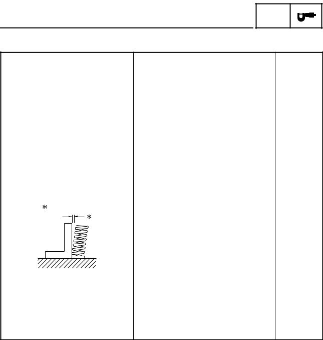
Spring tilt |
|
|
Intake |
---- |
2.5°/1.80 mm |
|
|
(2.5°/0.071 in) |
Exhaust |
---- |
2.5°/1.80 mm |
|
|
(2.5°/0.071 in) |
Winding direction (top view) |
|
|
Intake |
Clockwise |
---- |
Exhaust |
Clockwise |
---- |
– 4 –

– 4 –
|
|
|
|
|
|
|
|
CHASSIS SPECIFICATIONS |
|
SPEC |
|
||
|
|
|
|
|
|
|
EBS01003 |
|
|
|
|
|
|
|
|
|
|
|
|
|
CHASSIS SPECIFICATIONS |
|
|
|
|
|
|
|
|
|
|
|
|
|
Item |
|
Standard |
|
|
|
Limit |
|
|
|
|
|
|
|
Front wheel |
|
|
|
|
|
|
Type |
|
Panel wheel |
|
---- |
||
Rim size |
|
12 × 6.0 AT |
|
---- |
||
Rim material |
|
Aluminum (YFM7FGPX) |
|
---- |
||
|
|
Steel (YFM7FGX) |
|
|
|
|
Maximum radial wheel runout |
|
---- |
|
|
2.0 mm |
|
|
|
|
|
|
(0.08 in) |
|
Maximum lateral wheel runout |
|
---- |
|
|
2.0 mm |
|
|
|
|
|
|
(0.08 in) |
|
|
|
|
|
|
|
|
Rear wheel |
|
|
|
|
|
|
Type |
|
Panel wheel |
|
---- |
||
Rim size |
|
12 × 7.5 AT |
|
---- |
||
Rim material |
|
Aluminum (YFM7FGPX) |
|
---- |
||
|
|
Steel (YFM7FGX) |
|
|
|
|
Maximum radial wheel runout |
|
---- |
|
|
2.0 mm |
|
|
|
|
|
|
(0.08 in) |
|
Maximum lateral wheel runout |
|
---- |
|
|
2.0 mm |
|
|
|
|
|
|
(0.08 in) |
|
|
|
|
|
|
|
|
– 5 –
– 5 –
ELECTRICAL SPECIFICATIONS SPEC
EBS01004
ELECTRICAL SPECIFICATIONS
Item |
|
Standard |
Limit |
|
|
|
|
ECU |
|
|
|
Model/manufacturer |
F8T83472/MITSUBISHI |
---- |
|
|
|
|
|
Ignition coil |
|
|
|
Model/manufacturer |
2JN/YAMAHA |
---- |
|
Minimum ignition spark gap |
6.0 mm (0.24 in) |
---- |
|
Primary coil resistance |
2.16 |
~ 2.64 Ω at 20 °C (68 °F) |
---- |
Secondary coil resistance |
8.64 |
~ 12.96 kΩ at 20 °C (68 °F) |
---- |
Circuit breaker |
|
|
|
Circuit breaker type |
Fuse |
|
---- |
Fuses |
|
|
|
Main fuse |
40.0 |
A |
---- |
Headlight fuse |
15.0 |
A |
---- |
Signaling system fuse |
5.0 A |
---- |
|
Ignition fuse |
10.0 |
A |
---- |
Auxiliary DC jack fuse |
15.0 |
A |
---- |
Fuel injection system fuse |
15.0 |
A |
---- |
Four-wheel-drive motor fuse |
10.0 |
A |
---- |
EPS fuse |
40.0 |
A (YFM7FGPX only) |
---- |
Radiator fan motor fuse |
15.0 |
A |
---- |
Spare fuse |
40.0 |
A |
---- |
|
15.0 |
A |
---- |
|
10.0 |
A |
---- |
|
5.0 A |
---- |
|
|
|
|
|
– 6 –
 Loading...