


YP-X Series
Yamaha YP-X Series, YP320X, YP320XR, YP330X, YP340X Owner's Manual
...
OWNER'S MANUAL

Before using the “YP-X” series robot
(Be sure to read the following notes.)
At this time, our thanks for your purchase of this YAMAHA “YP-X” series robot.
The “YP-X” series robot use absolute position detectors that do not require return-to-origin
after turning on the controller power. However, when the controller power is turned on in the
following cases, return-to-origin must be performed just the very first time.
(1) When robot cable was first connected after delivery from YAMAHA.
(2) When robot cable was disconnected from the controller and then reconnected.
(3) When no absolute battery is connected.
(4) When a motor or cable was replaced.
At this point, any of the following errors is issued immediately after controller power is turned
on, but this is not a malfunction. The controller will operate normally by restarting.
When using DRCX or TRCX controllers:
15 : FEEDBACK ERROR 2
23 : ABS.BAT.L-VOLTAGE
24 : ABS.DATA.ERROR
When using a QRCX controller:
17.80 : D?.ABS.encoder backup error
17.81 : D?.ABS.encoder battery alarm
17.85 : D?.ABS.encoder system error
17.92 : D?.ABS.cable disconnected
17.93 : D?.ABS.data overflow
17.94 : D?.ABS.Battery degradation
[1] X, Y, Z axes
X, Y, Z axes use the stroke end origin detection method.
Set the origin position while referring to the following section in the robot controller
instruction manual.
When using DRCX or TRCX controllers:
See “9-1-1 Return-to-origin by the search method” in Chapter 9.
When using a QRCX controller:
See “11-9 Absolute Reset” in Chapter 11.
!
CAUTION
Changing the origin position may cause a positional shift or robot breakdowns,
and should be avoided. Changing the origin detection method might also create
a dangerous situation and should be avoided. If these must be changed, consult
our sales office or dealer.

[2] R axis
On the above robots, the customer should set the origin at the desired position.
Move the robot to the desired position and set it as the origin while referring to the
following section in the robot controller instruction manual.
When using DRCX or TRCX controllers:
See “9-1-1 Return-to-origin by the search method” in Chapter 9.
When using a QRCX controller:
See “11-9 Absolute Reset” in Chapter 11.
After setting the origin position, affix the stickers (triangular stickers supplied with the
robot) to both the tool side and workpiece side so that they can be used as the alignment
marks. Use these marks as the reference position the next time the origin must be set.

Introduction
Our sincere thanks for your purchase of this YAMAHA robot and controller.
The YP-X Series were designed and developed as compact and highspeed Pick
and Place (P&P) robots.
This manual contains important information on items such as an overview, handling, adjustment, and service of YP-X Series robots to ensure correct and efficient use. Please be sure to read this manual before installing the equipment.
Please refer to the "YAMAHA Robot Controller DRCX, TRCX, QRCX Instruction and Owner's Manual" for detailed information on operation and programming.
NOTES
◆ We reserve the right to make future product changes that might not be incorporated into this manual.
◆ We request the customer contact concerning any possible errors, omissions or
misprints etc.
YAMAHA MOTOR CO., LTD.
IM Company

MEMO

CONTENTS
CHAPTER 1 Using the Robot Safely
1 Safety Information................................................... 1-1
2 Essential Caution Items ........................................... 1-2
3 Special Training for Industrial Robot Operation...... 1-8
4 Robot Safety Functions............................................ 1-9
5 Safety Measures for the System ............................. 1-10
6 Trial Operation...................................................... 1-11
7 Work Within The Safeguards................................. 1-12
8 Automatic Operation ............................................ 1-13
9 Adjustment and Inspection.................................... 1-13
10 Repair and Modification........................................ 1-13
11 Warranty ............................................................... 1-14
12 CE Markings .......................................................... 1-15
13 Precautions ........................................................... 1-16
CHAPTER 2 Functions
1 P & P robot unit....................................................... 2-1
2 P & P robot controller ............................................. 2-2
CHAPTER 3 Installation
1 Robot Installation Conditions .................................. 3-1
1-1 Installation environments ............................................................... 3-1
2 Installation .............................................................. 3-3
2-1 Installation frame ........................................................................... 3-3
2-2 Installing the robot ......................................................................... 3-4
3 Connection of robot cables ..................................... 3-7
4 Protective Bonding .................................................. 3-9

CHAPTER 4 Adjustment
1 Outline .................................................................... 4-1
1-1 Robot parameter settings ................................................................ 4-2
2 Setting the origin position ....................................... 4-3
2-1 Mark method (R-axis) ..................................................................... 4-4
2-2 Stroke end method (X, Z, Y axes) ................................................... 4-5
3 Adjustment of the belt tension ................................ 4-6
3-1 Adjustment of X,Y, Z axis motor belt tension .................................. 4-6
3-2 Adjustment of Z axis tip belt tension
(YP320X, YP320XR, YP330X, YP340X) .......................................... 4-7
3-3 Adjustment of Z axis tip belt tension (YP220BX, YP220BXR) .......... 4-8
3-4 Adjust the X-axis belt tension (YP220BX, YP220BXR)..................... 4-9
CHAPTER 5 Periodic Inspecition
1 Introduction ............................................................ 5-1
2 Inspection ............................................................... 5-3
2-1 Daily Checklist .............................................................................. 5-3
2-2 Six Month Inspection ..................................................................... 5-4
3 Replacement of Motor ............................................ 5-5
3-1 Replacement of X, Y, Z axis motors
(YP320X, YP330X, YP340X, YP320XR) .......................................... 5-5
3-2 Replacement of X and Z axis motor (YP220BX, YP220BXR) ........... 5-7
3-3 Replacement of R axis motor (YP220BXR, YP320XR, YP340X)....... 5-8
4 Belt replacement method ........................................ 5-9
4-1 Replacement of the X and Z axis belts
(YP320X, YP330X, YP340X, YP320XR) .......................................... 5-9
4-2 Replacement of Y axis belt (YP330X, YP340X) ............................. 5-10
4-3 Replacement of Z axis belt (YP220BX, YP220BXR) ....................... 5-11
4-4 Replacement of X axis belt (YP220BX, YP220BXR) ...................... 5-12
4-5 Replacement of Z axis tip section belt
(YP320X, YP330X, YP340X, YP320XR) ........................................ 5-13
4-6 Replacement of Z axis tip section belt (YP220BX, YP220BXR) ..... 5-14
5 Sample troubleshooting......................................... 5-15
6 Spare parts list....................................................... 5-17

CHAPTER 6 Specifications
1 P & P robot unit....................................................... 6-1
1-1 Basic specifications ........................................................................ 6-1
1-2 Robot External Views ..................................................................... 6-2
1-3 Table of robot control signals ......................................................... 6-8
1-4 Piping and wiring of robot ........................................................... 6-14
2 R axis allowable moment/inertia moment ............. 6-18
2-1 R axis allowable moment/inertia moment .................................... 6-18
2-2 Equation for moment of inertia calculation .................................. 6-19
2-3 Example of moment of inertia calculation .................................... 6-21
3 Robot allowable duty ............................................ 6-23
4 Allowable overhang .............................................. 6-24
5 X-axis droop .......................................................... 6-25
6 Mechanical stopper ............................................... 6-26

MEMO

1 Safety Information ......................................... 1-1
2 Essential Caution Items .................................. 1-2
3
Special Training for Industrial Robot Operation ....
1-8
4 Robot Safety Functions .................................. 1-9
5 Safety Measures for the System ................... 1-10
6 Trial Operation ............................................ 1-11
7 Work Within The Safeguards ....................... 1-12
8 Automatic Operation................................... 1-13
9 Adjustment and Inspection .......................... 1-13
10 Repair and Modification .............................. 1-13
11 Warranty ..................................................... 1-14
12 CE Markings................................................. 1-15
13 Precautions .................................................. 1-16
CHAPTER 1
Using the Robot Safely

MEMO
CHAPTER 1 Using the Robot Safely
1-1
1 Safety Information
Industrial robots are highly programmable, mechanical devices that provide a
large degree of freedom when performing various manipulative tasks.
To ensure correct and safe use of YAMAHA industrial robots, carefully read this
manual and make yourself well acquainted with the contents. FOLLOW THE
WARNINGS, CAUTIONS AND INSTRUCTIONS INCLUDED IN THIS
MANUAL. Failure to take necessary safety measures or mishandling due to not
following the instructions in this manual may result in trouble or damage to the
robot and injury to personnel (robot operator or service personnel) including fatal
accidents.
Warning information in this manual is shown classified into the following items.
Failure to follow DANGER instructions will result in severe injury or
death to the robot operator, a bystander or a person inspecting or
repairing the robot.
Failure to follow WARNING instructions could result in severe injury or death to the robot operator, a bystander or a person inspecting or repairing the robot.
Failure to follow CAUTION instructions may result in injury to the robot
operator, a bystander or a person inspecting or repairing the robot, or damage to the robot and/or robot controller.
It is not possible to detail all safety items within the limited space of this manual.
So it is essential that the user have a full knowledge of basic safety rules and also
that the operator makes correct judgments on safety procedures during operation.
This manual and warning labels supplied with or affixed to the robot are written
in English. If the robot operator or service personnel does not understand English, do not permit him (or her) to handle the robot.
!
DANGER
WARNING
!
CAUTION
CHAPTER 1 Using the Robot Safely
1-2
2 Essential Caution Items
Particularly important cautions for handling or operating the robot are described
below. In addition, safety information about installation, operation, inspection
and maintenance is provided in each chapter. Be sure to comply with these instructions to ensure safe use of the robot.
(1) Observe the following cautions during automatic operation.
Warning labels 1 (Fig. 1-1) are affixed to the robot.
• Install a safeguard (protective enclosure) to keep any person from entering
within the movement range of the robot and suffering injury due to being
struck by moving parts.
• Install a safety interlock that triggers emergency stop when the door or
panel is opened.
• Install safeguards so that no one can enter inside except from doors or
panels equipped with safety interlocks.
• The warning labels 1 shown in Fig. 1-1 are supplied with the robot and
should be affixed to a conspicuous spot on doors or panels equipped with
safety interlocks.
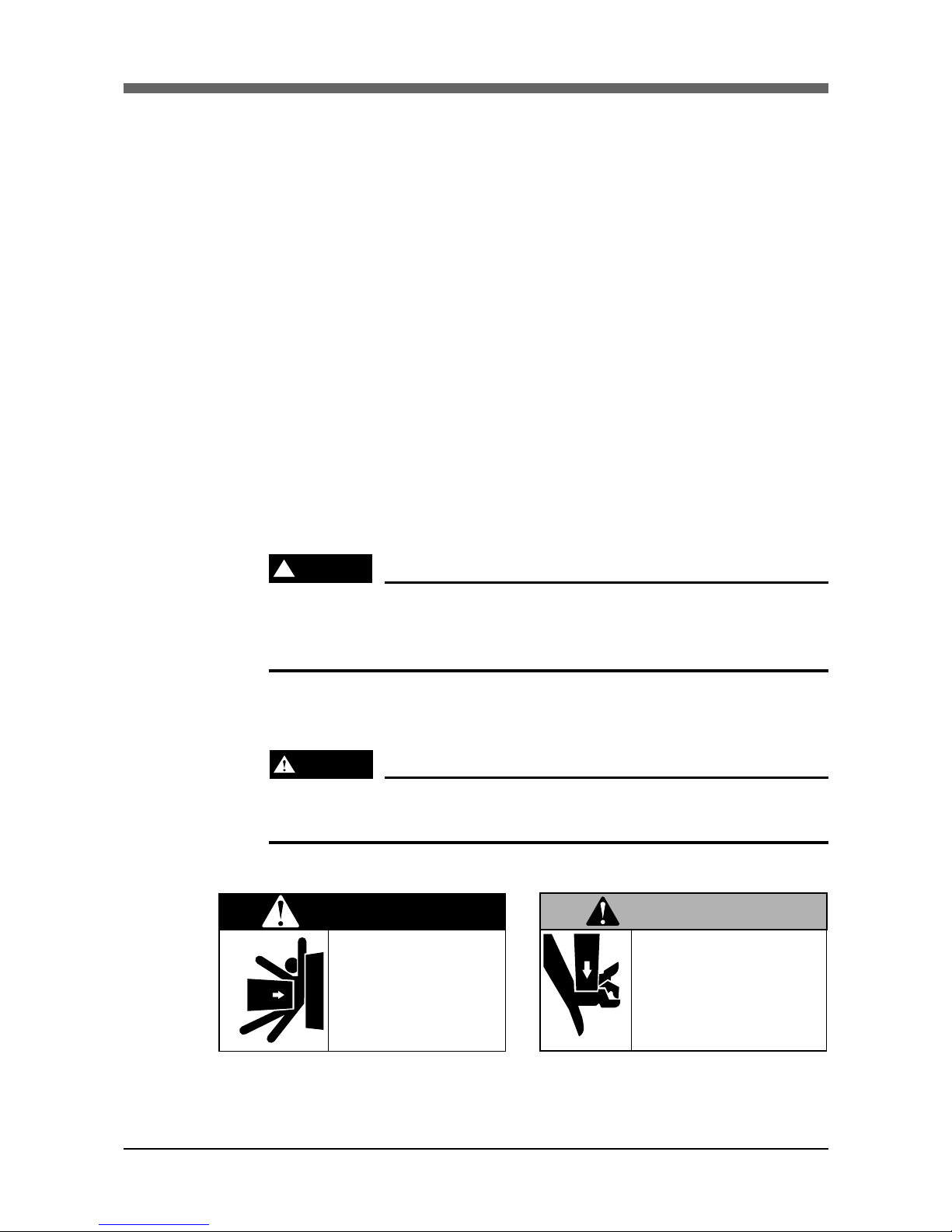
!
DANGER
Serious injury or death will result from impact with moving robot.
• Keep outside of guard during operation.
• Lock out power before approaching robot.
(2) Use caution to prevent hands or fingers from being pinched or crushed.
Warning labels 2 (Fig. 1-2) are affixed to the robot.
WARNING
Moving parts can pinch or crush.
Keep hands away from robot arms.
■Fig. 1-1 Warning label 1 ■Fig. 1-2 Warning label 2
DANGER
Serious injury or death
will result from impact
with moving robot.
• Keep outside of guard
during operation.
• Lock out power before
approaching robot.
Moving parts can
pinch or crush.
Keep hands away
from robot arms.
WARNING
CHAPTER 1 Using the Robot Safely
1-3
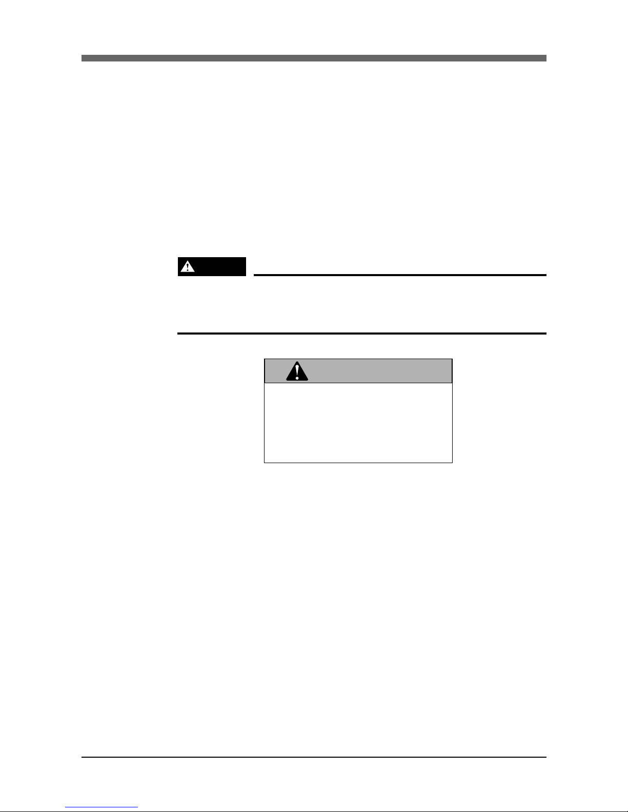
(3) Follow the instructions on warning labels and in this manual.
Warning label 3 (see Fig. 1-3) is supplied with the robot and should be affixed to the robot or a conspicuous spot near the robot.
• Be sure to read the warning label and this manual carefully and make your
thoroughly understand the contents before attempting installation and operation of the robot.
• Before starting the robot operation, even after you have read through this
manual, read again the corresponding procedures and cautions in this manual
as well as descriptions in the this chapter (Chapter 1, “Using the Robot
Safely”).
• Never install, adjust, inspect or service the robot in any manner that does
not comply with the instructions in this manual.
WARNING
Improper installation or operation can result in serious injury or
death.
Read owner’s manual and all warning labels before operation.
■Fig. 1-3 Warning label 3
Improper Installation or operation
can result in serious injury or
death.
Read owner's manual and all
warning labels before operation.
WARNING
CHAPTER 1 Using the Robot Safely
1-4
(4) Do not use the robot in environments containing inflammable gas, etc.
WARNING
• This robot was not designed for operation in environments where
inflammable or explosive substances are present.
• Do not use the robot in environments containing inflammable gas,
dust or liquids. Explosions or fire could otherwise result.
(5) Do not use the robot in locations possibly subject to electromagnetic
interference, etc.
WARNING
Avoid using the robot in locations subject to electromagnetic interference, electrostatic discharge or radio frequency interference.
Malfunction may otherwise occur.
(6) Use caution when releasing the Z-axis (vertical axis) brake.
WARNING
The Z-axis will slide down when the Z-axis brake is released, causing a hazardous situation.
• Press the emergency stop button and prop up the Z-axis with a
support stand before releasing the brake.
• Use caution not to let your body get caught between the Z-axis
and installation base when releasing the brake to perform direct
teach.
(7) Provide safety measures for end effector (gripper, etc.).
WARNING
• End effectors must be designed and manufactured so that they
cause no hazards (for example, loosening of workpiece) even if
power (electricity, air pressure, etc.) is shut off or power fluctuations occur.
• If there is a possible danger that the object gripped by the end
effector may fly off or drop, then provide appropriate safety protection taking into account the object size, weight, temperature
and chemical properties.

CHAPTER 1 Using the Robot Safely
1-5
(8) Use the following caution items when removing the Z-axis motor.
WARNING
The Z-axis will drop when the Z-axis motor is removed, possibly
resulting in injury.
• Turn off the controller and set a support stand under the Z-axis
before removing the motor.
• Use caution not to allow hands or body to be squeezed or crushed
by moving parts on the Z-axis or between the Z-axis and the installation base.
(9) Use the following caution during inspection of controller.
WARNING
• When you need to touch the terminals or connectors on the outside of the controller during inspection, always first turn off the
controller power switch and also the power source in order to
prevent possible electrical shock.
• Never touch any internal parts of the controller.
• For more specific safety items on the controller, refer to the
YAMAHA Robot Controller Owner’s Manual.
(10) Consult us for corrective action when the robot is damaged or malfunc-
tion occurs.
WARNING
If any part of the robot is damaged or any malfunction occurs, continuous operation may be very dangerous. Please consult YAMAHA
dealer for corrective action.
Damage or Trouble Possible Danger
Damage to machine harness or robot cable Electrical shock, malfunction of robot
Damage to exterior of robot
Flying outwards of damaged parts during robot
operation
Abnormal operation of robot
(positioning error, excessive vibration, etc.)
Malfunction of robot
Z-axis brake trouble Dropping of load

CHAPTER 1 Using the Robot Safely
1-6
(11) Use caution not to touch the cooling fan on the controller rear panel.
WARNING
• Bodily injury may occur from coming into contact with the cooling fan while it is rotating.
• When removing the fan cover for inspection, first turn off the controller and make sure the fan has stopped.
(12) Use caution not to touch the high temperature part of the motor.
WARNING
The motor is extremely hot after automatic operation, so burns may
occur if it is touched.
Before touching the motor during inspections or servicing, turn off
the controller, wait for a while and check that the temperature has
cooled.
(13) Do not remove, alter or stain the warning labels.
WARNING
If warning labels are removed or difficult to see, necessary cautions may not be taken, resulting in an accident.
• Do not remove, alter or stain the warning labels on the robot.
• Do not allow the warning labels to be hidden by the device in-
stalled to the robot by the user.
• Provide proper lighting so that the symbols and instructions on
the warning labels can be clearly seen even from the outside of
safeguards.
(14) Protective bonding
WARNING
Be sure to ground the robot and controller to prevent electrical
shock.
CHAPTER 1 Using the Robot Safely
1-7
(15) Be sure to make correct parameter settings.
!
CAUTION
The robot must be operated with correct tolerable moment of inertia and
acceleration coefficients according to the manipulator tip mass and moment of inertia. If this is not observed, premature end to the life of the drive
units, damage to the robot parts or residual vibration during positioning
may result.
(16) Do not use the robot for tasks requiring motor thrust.
!
CAUTION
Avoid using the robots for tasks which make use of motor thrust (pressfitting, burr removal, etc.). These tasks may cause malfunctions of the robot.

CHAPTER 1 Using the Robot Safely
1-8
3 Special Training for Industrial Robot Operation
Companies or factories using industrial robots must make sure that every person,
who handles the robot such as for teaching, programming, movement check, inspection, adjustment and repair, has received appropriate training and also has
the skills needed to perform the job correctly and safely.
Since the YAMAHA YP-X Series pick-and-place robots fall under the industrial
robot category, the user must observe local regulations and safety standards for
industrial robots, and provide special training for every person involved in robotrelated tasks (teaching, programming, movement check, inspection, adjustment,
repair, etc.).
CHAPTER 1 Using the Robot Safely
1-9
4 Robot Safety Functions
(1) Overload detection
This function detects an overload applied to the motor and shuts off the servo
power.
(2) Overheat detection
This detects an abnormal temperature rise in the controller’s driver and shuts
off the servo power.
If an overload or overheat error occurs, take the following measures.
1. Insert a timer in the program.
2. Reduce the acceleration coefficient.
(3) Soft limits
Soft limits can be set on each axis to limit the working envelope in manual
operation after return-to-origin and during automatic operation.
The working envelope is the area limited by soft limits.
(4) Mechanical stoppers
If the servo power is suddenly shut off during high-speed operation by emergency stop or safety functions, these mechanical stoppers prevent the axis
from exceeding the movement range. The R-axis has no mechanical stopper.
The movement range is the area limited by mechanical stoppers.
WARNING
Axis movement does not stop immediately after the servo power
supply is shut off by emergency stop or other safety functions.
(5) Z-axis (vertical axis) brake (Option)
An electromagnetic brake can be installed to the Z-axis as an option, to prevent
the Z-axis from sliding down when the servo power is turned off. This brake is
working when the controller is off or the Z-axis servo power is off even when
the controller is on. The Z-axis brake can be released by means of the programming unit or by a command in the program when the controller is on.
WARNING
The Z-axis will slide down when the Z-axis brake is released, causing a hazardous situation.
• Press emergency stop button and prop the Z-axis with a support
stand before releasing the brake.
• Use caution not to let your body get caught between the Z-axis and
installation base when releasing the brake to perform direct teach.
WARNING
Axis movement does not stop immediately after the servo power
supply is shut off by emergency stop or other safety functions.

CHAPTER 1 Using the Robot Safely
1-10
5 Safety Measures for the System
Since the robot is commonly used in conjunction with an automated system, a
dangerous situation is more likely to occur from the automated system than from
the robot itself. Accordingly, appropriate safety measures must be taken on the
part of the system manufacturer according to the individual system. The system
manufacturer should provide a proper instruction manual for safe, correct operation and servicing of the system.

CHAPTER 1 Using the Robot Safely
1-11
6 Trial Operation
After installation, adjustment, inspection, maintenance or repair of the robot has
been done, perform a trial operation using the following procedures.
(1) If a safeguard has not yet been provided right after installation of the robot,
rope off or chain off around the movement area of the manipulator in place of
the safeguard, and observe the following points.
q Use stable posts which do not totter easily.
w The rope or chain should be easily visible by everyone around the robot.
e Place a conspicuous sign prohibiting the operator or other personnel from
entering the movement range of the manipulator.
(2) Check the following points before turning on the controller.
q Is the robot securely and correctly installed?
w Are the electrical connections to the robot correct?
e Are items such as air pressure correctly supplied?
r Is the robot correctly connected to peripheral equipment?
t Have safety measures (safeguard enclosure, etc.) been taken?
y Does the installation environment meet the specified standards.
(3) After the controller is turned on, check the following points from outside the
safeguard.
q Does the robot start and stop as intended? Can the operation mode be
selected correctly?
w Does each axis move as intended within the soft limits?
e Does the end effector move as intended?
r Are the signal transmissions to the end effector and peripheral equipment
correct?
t Does emergency stop work?
y Are the teaching and playback functions normal?
u Are the safeguard and interlock working as intended?
i Does the robot move correctly during automatic operation?

CHAPTER 1 Using the Robot Safely
1-12
7 Work Within The Safeguards
(1) When work is required inside the safeguard enclosure, always turn off the
controller and place a sign indicating that the robot is being adjusted or serviced in order to keep any other person from inadvertently touching the controller switch or operation panel, except for the following cases.
1) Soft limit settings
2) Teaching
For items 1), follow the precautions and procedure for each section. To perform item 2), refer to the description in (2) below.
(2) Teaching
When performing teaching within the safeguard enclosure, comply with the
instructions listed below.
1) Check or perform the following points from outside the safeguard enclosure.
q Make sure that no hazards are present within the safeguard enclosure
by visual check.
w Check that the programming unit MPB or TPB operates correctly.
e Check that no failures are found in the robot.
r Check that emergency stop works correctly.
t Select teaching mode and prohibit automatic operation.
2) Never enter the movement range of the manipulator while within the safeguard enclosure.

CHAPTER 1 Using the Robot Safely
1-13
8 Automatic Operation
Automatic operation described here includes all operations in AUTO mode.
(1) Check the following before starting automatic operation.
q No one is within the safeguard enclosure.
w The programming unit and tools are in their specified locations.
e The alarm or error lamps on the robot and peripheral equipment do not
flash.
r The safeguard is securely installed with safety interlocks actuated.
(2) Observe the following during automatic operation or in cases where an error
occurs.
1) After automatic operation has started, check the operation status and warning lamp to ensure that the robot is in automatic operation.
2) Never enter the safeguard during automatic operation.
3) If an error occurs in the robot or peripheral equipment, observe the following procedure before entering the safeguard enclosure.
q Press the emergency stop button to set the robot to emergency stop.
w Place a sign on the start switch, indicating that the robot is being in-
spected in order to keep any other person from inadvertently touching
the switch and restarting the robot.
9 Adjustment and Inspection
Do not attempt any installation, adjustment, inspection and maintenance that is
not described in this manual.
10 Repair and Modification
Do not attempt any repair, parts replacement and modification not described in
this manual. These works require technical knowledge and skill, and may also
involve work hazards.

CHAPTER 1 Using the Robot Safely
1-14
11 Warranty
The YAMAHA robot and/or related product you have purchased are warranted
against the defects or malfunctions as described below.
Warranty description : If a failure or breakdown occurs due to defects
in materials or workmanship in the genuine
parts constituting this YAMAHA robot and/or
related product within the warranty period, then
YAMAHA will repair or replace those parts free
of charge (hereafter called "warranty repair").
Warranty Period : The warranty period ends when any of the fol-
lowing applies:
(1) After 18 months (one and a half year) have
elapsed from the date of shipment
(2) After one year has elapsed from the date of
installation
(3) After 2,400 hours of operation
Exceptions to the Warranty : This warranty will not apply in the following
cases:
(1) Fatigue arising due to the passage of time,
natural wear and tear occurring during operation (natural fading of painted or plated
surfaces, deterioration of parts subject to
wear, etc.)
(2) Minor natural phenomena that do not affect
the capabilities of the robot and/or related
product (noise from computers, motors,
etc.).
(3) Programs, point data and other internal data
that were changed or created by the user.
Failures resulting from the following causes are not covered by warranty repair.
1) Damage due to earthquakes, storms, floods, thunderbolt, fire or any other
natural or man-made disasters.
2) Troubles caused by procedures prohibited in this manual.
3) Modifications to the robot and/or related product not approved by
YAMAHA or YAMAHA sales representatives.
4) Use of any other than genuine parts and specified grease and lubricants.
5) Incorrect or inadequate maintenance and inspection.
6) Repairs by other than authorized dealers.

CHAPTER 1 Using the Robot Safely
1-15
YAMAHA MOTOR CO., LTD. MAKES NO OTHER EXPRESS OR IMPLIED
WARRANTIES, INCLUDING ANY IMPLIED WARRANTY OF
MERCHANTABILITY OR FITNESS FOR ANY PARTICULAR PURPOSE.
THE WARRANTY SET FORTH ABOVE IS EXCLUSIVE AND IS IN LIEU
OF ALL EXPRESSED OR IMPLIED WARRANTIES, INCLUDING WARRANTIES OF MERCHANTABILITY, FITNESS FOR A PARTICULAR PURPOSE,
OR WARRANTIES ARISING FROM A COURSE OF DEALING OR USAGE
OF TRADE.
YAMAHA MOTOR CO., LTD. SOLE LIABILITY SHALL BE FOR THE DELIVERY OF THE EQUIPMENT AND YAMAHA MOTOR CO., LTD. SHALL
NOT BE LIABLE FOR ANY CONSEQUENTIAL DAMAGES (WHETHER
ARISING FROM CONTRACT, WARRANTY, NEGLIGENCE OR STRICT
LIABILITY). YAMAHA MOTOR CO., LTD. MAKES NO WARRANTY WHATSOEVER WITH REGARD TO ACCESSORIES OR PARTS NOT SUPPLIED
BY YAMAHA MOTOR CO., LTD.
12 CE Markings
For information about CE markings relating to cases in which the YAMAHA
robot is exported to or used in European countries, refer to the separate “YAMAHA
QRCX-E Robot Controller Owner’s Manual”.

CHAPTER 1 Using the Robot Safely
1-16
13 Precautions
1) Accuracy may deteriorate due to external causes such as temperature and
humidity and may result in equipment breakdowns. Use of the robot in airconditioned facilities is recommended. Do not use in environments exposed
to items such as oil, water, corrosive gases and metal powder etc.
2) When using the robot after an extended period of non-use, warmup the robot
for about a 10 minute period with no workpiece installed. This will improved
the sliding operation of the mechanism.
3) If the work (including the gripper or tool) is heavier than the maximum payload listed in the catalog or the robots own basic settings are changed, this
may cause the robot itself to breakdown. Do not use the robot under such
conditions.
4) Because of the one-sided support structure, the YP-X series manipulator arm
droops downward slightly when it moves to the X-axis stroke end (forward
end). For example, the manipulator arm will droop a maximum of 1.5
millimeters with a payload of 3kg, so take this into consideration during the
application design stage.
5) If the robot movement duty is too high, errors such as "Overload" and "Overheat" may occur. In this case, increase the time that the robot axis is stopped
by inserting a timer in the program, etc.
6) The YAMAHA pick and place robot uses the stroke-end origin detection
method. In this method, a large electrical current flows through the motor, so
avoid performing absolute reset frequently to prolong the controller and motor service life.
7) The axes on the YP-X series are belt-driven (see specifications). Using the
motor to apply thrust (press-fit, etc.) may sometimes cause the teeth on the
belt to jump free. So use caution not to apply a large force greater than the
maximum payload listed in the specs for the Z-axis.
8) On the YP-X series, a slight residual vibration may sometimes occur during
positioning of each axis due to the one-sided support structure and the belt
drive. So install a timer if precise positioning is required.

CHAPTER 2
Functions
1 P & P robot unit ............................................. 2-1
2 P & P robot controller.................................... 2-2

MEMO
 Loading...