


 Loading...
YFM700RV
SERVICE MANUAL
LIT-11616-19-13 |
1S3-28197-10 |

EBS00001
YFM700RV
SERVICE MANUAL
©2005 by Yamaha Motor Corporation, U.S.A. First Edition, May 2005
All rights reserved.
Any reproduction or unauthorized use without the written permission of Yamaha Motor Corporation, U.S.A. is expressly prohibited.
Printed in U.S.A.
LIT-11616-19-13

EBS00002
NOTICE
This manual was produced by the Yamaha Motor Company primarily for use by Yamaha dealers and their qualified mechanics. It is not possible to include all the knowledge of a mechanic in one manual, so it is assumed that anyone who uses this book to perform maintenance and repairs on Yamaha vehicle has a basic understanding of the mechanical ideas and the procedures of vehicle repair. Repairs attempted by anyone without this knowledge are likely to render the vehicle unsafe and unfit for use.
Yamaha Motor Company, Ltd. is continually striving to improve all its models. Modifications and significant changes in specifications or procedures will be forwarded to all authorized Yamaha dealers and will appear in future editions of this manual where applicable.
NOTE:
Designs and specifications are subject to change without notice.
EBS00003
IMPORTANT INFORMATION
Particularly important information is distinguished in this manual by the following notations.
 WARNING
CAUTION:
NOTE:
The Safety Alert Symbol means ATTENTION! BECOME ALERT! YOUR SAFETY IS INVOLVED!
Failure to follow WARNING instructions could result in severe injury or death to the vehicle operator, a bystander or a person checking or repairing the vehicle.
A CAUTION indicates special precautions that must be taken to avoid damage to the vehicle.
A NOTE provides key information to make procedures easier or clearer.

EBS00004
HOW TO USE THIS MANUAL
MANUAL ORGANIZATION
This manual consists of chapters for the main categories of subjects. (See “symbols”)
1st title 1: This is the title of the chapter with its symbol in the upper right corner of each page. 2nd title 2: This title indicates the section of the chapter and only appears on the first page of each section. It is located in the upper left corner of the page.
3rd title 3: This title indicates a sub-section that is followed by step-by-step procedures accompanied by corresponding illustrations.
EXPLODED DIAGRAMS
To help identify parts and clarify procedure steps, there are exploded diagrams at the start of each removal and disassembly section.
1.An easy-to-see exploded diagram 4 is provided for removal and disassembly jobs.
2.Numbers 5 are given in the order of the jobs in the exploded diagram. A number that is enclosed by a circle indicates a disassembly step.
3.An explanation of jobs and notes is presented in an easy-to-read way by the use of symbol marks 6. The meanings of the symbol marks are given on the next page.
4.A job instruction chart 7 accompanies the exploded diagram, providing the order of jobs, names of parts, notes in jobs, etc.
5.For jobs requiring more information, the step-by-step format supplements 8 are given in addition to the exploded diagram and the job instruction chart.

1 |
|
|
2 |
|
GEN |
|
|
SPEC |
|
INFO |
|
|
|
|
|
|
|
|
|
3 |
|
|
4 |
|
CHK |
|
|
ENG |
|
ADJ |
|
|
|
|
|
|
|
|
|
5 |
|
|
6 |
|
COOL |
|
|
FI |
|
7 |
|
|
8 |
|
CHAS |
|
|
ELEC – |
+ |
9 |
|
|
0 |
|
TRBL |
|
|
|
|
SHTG |
|
|
|
|
A |
|
|
B |
|
C |
|
|
D |
|
|
|
|
T |
|
|
|
|
. |
|
|
|
|
R |
|
|
|
|
. |
|
E |
F |
|
G |
|
H |
I |
|
J |
|
E |
|
G |
M |
|
K |
L |
|
M |
|
B |
|
LS |
M |
|
N |
|
|
O |
|
LT |
|
|
New |
|
|
|
|
|
EBS00006
SYMBOLS
The following symbols are not relevant to every vehicle.
Symbols 1 to 9 indicate the subject of each chapter.
1 General information
2Specifications
3Periodic checks and adjustments
4Engine
5Cooling system
6Fuel injection system
7Chassis
8Electrical
9Troubleshooting
Symbols 0 to G indicate the following.
0 Serviceable with engine mounted A Filling fluid
BLubricant
CSpecial tool
DTightening torque
EWear limit, clearance
FEngine speed
GElectrical data (Ω, V, A)
Symbols H to M in the exploded diagrams indicate the types of lubricants and lubrication points.
H Apply engine oil I Apply gear oil
J Apply molybdenum disulfide oil K Apply wheel bearing grease
LApply lithium-soap-based grease
MApply molybdenum disulfide grease
Symbols N to O in the exploded diagrams indicate where to apply a locking agent N and when to install a new part O.
NApply the locking agent (LOCTITE®)
OReplace

EBS00008
TABLE OF CONTENTS
GENERAL INFORMATION |
|
|
|
INFOGEN |
1 |
||
|
|||
|
|
|
|
SPECIFICATIONS |
|
|
|
SPEC |
2 |
||
|
|||
|
|
|
|
PERIODIC CHECKS AND |
|
|
|
ADJUSTMENTS |
CHKADJ |
3 |
ENGINE
ENG 4
COOLING SYSTEM
COOL 5
FUEL INJECTION SYSTEM
FI 6
CHASSIS
CHAS 7
– |
+ |
ELECTRICAL |
8 |
ELEC |
TROUBLESHOOTING SHTGTRBL 9

CONTENTS
CHAPTER 1
GENERAL INFORMATION
VEHICLE IDENTIFICATION............................................................................ |
1-1 |
VEHICLE IDENTIFICATION NUMBER ..................................................... |
1-1 |
MODEL LABEL.......................................................................................... |
1-1 |
FEATURES...................................................................................................... |
1-2 |
OUTLINE OF THE FI SYSTEM................................................................. |
1-2 |
FI SYSTEM................................................................................................ |
1-3 |
SELF-ADJUSTING PARKING BRAKE MECHANISM............................... |
1-4 |
IMPORTANT INFORMATION ......................................................................... |
1-7 |
PREPARATION FOR REMOVAL AND DISASSEMBLY........................... |
1-7 |
REPLACEMENT PARTS........................................................................... |
1-7 |
GASKETS, OIL SEALS AND O-RINGS .................................................... |
1-7 |
LOCK WASHERS/PLATES AND COTTER PINS ..................................... |
1-8 |
BEARINGS AND OIL SEALS .................................................................... |
1-8 |
CIRCLIPS .................................................................................................. |
1-8 |
CHECKING THE CONNECTIONS............................................................ |
1-9 |
SPECIAL TOOLS .......................................................................................... |
1-10 |
CHAPTER 2 |
|
SPECIFICATIONS |
|
GENERAL SPECIFICATIONS ........................................................................ |
2-1 |
ENGINE SPECIFICATIONS ............................................................................ |
2-4 |
CHASSIS SPECIFICATIONS ........................................................................ |
2-12 |
ELECTRICAL SPECIFICATIONS ................................................................. |
2-14 |
TIGHTENING TORQUES .............................................................................. |
2-16 |
ENGINE TIGHTENING TORQUES ........................................................ |
2-16 |
CHASSIS TIGHTENING TORQUES ...................................................... |
2-19 |
HOW TO USE THE CONVERSION TABLE.................................................. |
2-22 |
GENERAL TIGHTENING TORQUE SPECIFICATIONS............................... |
2-22 |

LUBRICATION POINTS AND LUBRICANT TYPES .................................... |
2-23 |
ENGINE................................................................................................... |
2-23 |
COOLANT FLOW DIAGRAMS ..................................................................... |
2-24 |
OIL FLOW DIAGRAMS ................................................................................. |
2-28 |
CABLE ROUTING ......................................................................................... |
2-33 |
CHAPTER 3 |
|
PERIODIC CHECKS AND ADJUSTMENTS |
|
INTRODUCTION.............................................................................................. |
3-1 |
PERIODIC MAINTENANCE CHART FOR THE EMISSION CONTROL |
|
SYSTEM ......................................................................................................... |
3-1 |
GENERAL MAINTENANCE AND LUBRICATION CHART............................ |
3-2 |
SEAT, FENDERS AND FUEL TANK .............................................................. |
3-3 |
REMOVING THE FUEL TANK .................................................................. |
3-9 |
REMOVING THE FUEL PUMP ................................................................. |
3-9 |
INSTALLING THE FUEL PUMP.............................................................. |
3-10 |
INSTALLING THE FUEL HOSE .............................................................. |
3-10 |
ENGINE ......................................................................................................... |
3-11 |
ADJUSTING THE VALVE CLEARANCE ................................................ |
3-11 |
ADJUSTING THE ENGINE IDLING SPEED ........................................... |
3-13 |
ADJUSTING THE THROTTLE LEVER FREE PLAY .............................. |
3-14 |
ADJUSTING THE SPEED LIMITER........................................................ |
3-15 |
CHECKING THE SPARK PLUG ............................................................. |
3-16 |
CHECKING THE IGNITION TIMING....................................................... |
3-17 |
MEASURING THE COMPRESSION PRESSURE.................................. |
3-18 |
CHECKING THE ENGINE OIL LEVEL.................................................... |
3-20 |
CHANGING THE ENGINE OIL ............................................................... |
3-22 |
ADJUSTING THE CLUTCH CABLE........................................................ |
3-25 |
CLEANING THE AIR FILTER ELEMENT................................................ |
3-25 |
CHECKING THE THROTTLE BODY JOINT........................................... |
3-27 |
CHECKING THE FUEL HOSE ................................................................ |
3-28 |
CHECKING THE BREATHER HOSES ................................................... |
3-28 |
CHECKING THE COOLANT LEVEL....................................................... |
3-29 |
CHANGING THE COOLANT................................................................... |
3-29 |
CHECKING THE COOLING SYSTEM .................................................... |
3-32 |
CHECKING THE COOLANT TEMPERATURE WARNING LIGHT......... |
3-33 |
CHECKING THE EXHAUST SYSTEM.................................................... |
3-34 |
CLEANING THE SPARK ARRESTER .................................................... |
3-34 |

CHASSIS ....................................................................................................... |
3-36 |
ADJUSTING THE FRONT BRAKE ......................................................... |
3-36 |
ADJUSTING THE REAR BRAKE............................................................ |
3-36 |
ADJUSTING THE PARKING BRAKE...................................................... |
3-37 |
CHECKING THE BRAKE FLUID LEVEL................................................. |
3-38 |
CHECKING THE FRONT BRAKE PADS ................................................ |
3-39 |
CHECKING THE REAR BRAKE PADS .................................................. |
3-39 |
ADJUSTING THE REAR BRAKE LIGHT SWITCH ................................. |
3-40 |
CHECKING THE BRAKE HOSES........................................................... |
3-40 |
BLEEDING THE HYDRAULIC BRAKE SYSTEM ................................... |
3-41 |
ADJUSTING THE SHIFT PEDAL............................................................ |
3-43 |
ADJUSTING THE REVERSE CONTROL CABLE .................................. |
3-43 |
ADJUSTING THE DRIVE CHAIN SLACK ............................................... |
3-44 |
CHECKING THE STEERING SYSTEM .................................................. |
3-46 |
ADJUSTING THE TOE-IN....................................................................... |
3-46 |
CHECKING THE FRONT AND REAR SHOCK ABSORBERS ............... |
3-48 |
ADJUSTING THE FRONT SHOCK ABSORBERS ................................. |
3-48 |
ADJUSTING THE REAR SHOCK ABSORBER ...................................... |
3-49 |
CHECKING THE TIRES.......................................................................... |
3-52 |
CHECKING THE WHEELS ..................................................................... |
3-54 |
CHECKING AND LUBRICATING THE CABLES .................................... |
3-54 |
LUBRICATING THE LEVERS AND PEDALS ......................................... |
3-55 |
ELECTRICAL SYSTEM................................................................................. |
3-56 |
CHECKING AND CHARGING THE BATTERY....................................... |
3-56 |
CHECKING THE FUSES ........................................................................ |
3-62 |
ADJUSTING THE HEADLIGHT BEAMS................................................. |
3-64 |
REPLACING A HEADLIGHT BULB ........................................................ |
3-64 |
CHAPTER 4 |
|
ENGINE |
|
ENGINE REMOVAL ........................................................................................ |
4-1 |
MUFFLER AND EXHAUST PIPES ........................................................... |
4-1 |
INSTALLING THE EXHAUST PIPES AND MUFFLER ............................. |
4-2 |
OIL TANK .................................................................................................. |
4-3 |
LEADS, CABLES AND HOSES ................................................................ |
4-4 |
ENGINE MOUNTING BOLTS ................................................................... |
4-6 |
INSTALLING THE ENGINE....................................................................... |
4-8 |
CYLINDER HEAD............................................................................................ |
4-9 |
REMOVING THE CYLINDER HEAD....................................................... |
4-11 |
CHECKING THE CYLINDER HEAD ....................................................... |
4-12 |
CHECKING THE TAPPET COVERS AND CAMSHAFT SPROCKET |
|
COVER................................................................................................... |
4-13 |
CHECKING THE TIMING CHAIN TENSIONER...................................... |
4-13 |
CHECKING THE CAMSHAFT SPROCKET............................................ |
4-13 |
INSTALLING THE CYLINDER HEAD ..................................................... |
4-13 |

ROCKER ARMS AND CAMSHAFT .............................................................. |
4-17 |
REMOVING THE ROCKER ARMS AND CAMSHAFT............................ |
4-19 |
CHECKING THE CAMSHAFT................................................................. |
4-19 |
CHECKING THE DECOMPRESSION SYSTEM..................................... |
4-20 |
CHECKING THE ROCKER ARMS AND ROCKER ARM SHAFTS ........ |
4-21 |
INSTALLING THE CAMSHAFT AND ROCKER ARMS .......................... |
4-22 |
VALVES AND VALVE SPRINGS.................................................................. |
4-24 |
REMOVING THE VALVES AND VALVE SPRINGS ............................... |
4-25 |
CHECKING THE VALVES AND VALVE SPRINGS ................................ |
4-26 |
INSTALLING THE VALVES AND VALVE SPRINGS .............................. |
4-31 |
CYLINDER AND PISTON.............................................................................. |
4-33 |
REMOVING THE PISTON ...................................................................... |
4-34 |
CHECKING THE CYLINDER AND PISTON ........................................... |
4-34 |
CHECKING THE PISTON RINGS........................................................... |
4-36 |
CHECKING THE PISTON PIN ................................................................ |
4-37 |
INSTALLING THE PISTON AND CYLINDER ......................................... |
4-38 |
A.C. MAGNETO............................................................................................. |
4-41 |
REMOVING THE A.C. MAGNETO ROTOR............................................ |
4-43 |
CHECKING THE STATOR COIL |
|
AND CRANKSHAFT POSITION SENSOR ............................................ |
4-43 |
CHECKING THE STARTER CLUTCH .................................................... |
4-44 |
CHECKING THE TORQUE LIMITER...................................................... |
4-45 |
INSTALLING THE A.C. MAGNETO ROTOR .......................................... |
4-45 |
CLUTCH ........................................................................................................ |
4-47 |
REMOVING THE CLUTCH ..................................................................... |
4-51 |
REMOVING THE PRIMARY DRIVE GEAR |
|
AND BALANCER DRIVEN GEAR .......................................................... |
4-52 |
CHECKING THE FRICTION PLATES..................................................... |
4-52 |
CHECKING THE CLUTCH PLATES ....................................................... |
4-53 |
CHECKING THE CLUTCH SPRINGS..................................................... |
4-53 |
CHECKING THE CLUTCH HOUSING .................................................... |
4-54 |
CHECKING THE CLUTCH BOSS........................................................... |
4-54 |
CHECKING THE PRESSURE PLATE .................................................... |
4-54 |
CHECKING THE PULL LEVER SHAFT AND PULL ROD ...................... |
4-54 |
CHECKING THE PRIMARY DRIVE GEARS .......................................... |
4-55 |
CHECKING THE BALANCER DRIVE GEARS ....................................... |
4-55 |
INSTALLING THE PRIMARY DRIVE GEAR |
|
AND BALANCER DRIVEN GEARS ....................................................... |
4-55 |
INSTALLING THE CLUTCH.................................................................... |
4-56 |
OIL PUMP...................................................................................................... |
4-59 |
CHECKING THE OIL PUMP ................................................................... |
4-61 |
ASSEMBLING THE OIL PUMP............................................................... |
4-62 |
SHIFT SHAFT................................................................................................ |
4-63 |
CHECKING THE SHIFT SHAFT ............................................................. |
4-65 |
CHECKING THE STOPPER LEVER ...................................................... |
4-65 |
CHECKING THE SHIFT GUIDE.............................................................. |
4-65 |
CHECKING THE SHIFT DRUM SEGMENT ........................................... |
4-65 |
INSTALLING THE SHIFT LEVER ........................................................... |
4-65 |
INSTALLING THE SHIFT SHAFT ........................................................... |
4-66 |
CRANKCASE ................................................................................................ |
4-67 |
CRANKCASE BEARINGS....................................................................... |
4-69 |
SEPARATING THE CRANKCASE.......................................................... |
4-70 |
CHECKING THE OIL STRAINER ........................................................... |
4-70 |
CHECKING THE TIMING CHAIN AND GUIDE....................................... |
4-71 |
CHECKING THE BEARINGS AND OIL SEALS...................................... |
4-71 |
CHECKING THE CRANKCASE .............................................................. |
4-71 |
ASSEMBLING THE CRANKCASE.......................................................... |
4-72 |
CRANKSHAFT .............................................................................................. |
4-74 |
CRANKSHAFT AND BALANCER ........................................................... |
4-74 |
REMOVING THE CRANKSHAFT ........................................................... |
4-75 |
CHECKING THE CRANKSHAFT ............................................................ |
4-75 |
INSTALLING THE CRANKSHAFT .......................................................... |
4-76 |
TRANSMISSION............................................................................................ |
4-77 |
MAIN AXLE ............................................................................................. |
4-79 |
DRIVE AXLE ........................................................................................... |
4-80 |
COUNTER AXLE..................................................................................... |
4-82 |
CHECKING THE SHIFT FORKS............................................................. |
4-83 |
CHECKING THE SHIFT DRUM ASSEMBLY.......................................... |
4-83 |
CHECKING THE TRANSMISSION ......................................................... |
4-83 |
ASSEMBLING THE MAIN AXLE AND DRIVE AXLE .............................. |
4-84 |
INSTALLING THE TRANSMISSION ....................................................... |
4-85 |
CHAPTER 5 |
|
COOLING SYSTEM |
|
RADIATOR ...................................................................................................... |
5-1 |
CHECKING THE RADIATOR.................................................................... |
5-3 |
INSTALLING THE RADIATOR.................................................................. |
5-4 |
THERMOSTAT ................................................................................................ |
5-5 |
CHECKING THE THERMOSTAT.............................................................. |
5-6 |
INSTALLING THE THERMOSTAT............................................................ |
5-6 |
WATER PUMP................................................................................................. |
5-7 |
DISASSEMBLING THE WATER PUMP.................................................... |
5-9 |
CHECKING THE WATER PUMP .............................................................. |
5-9 |
ASSEMBLING THE WATER PUMP........................................................ |
5-10 |

CHAPTER 6
FUEL INJECTION SYSTEM
FUEL INJECTION SYSTEM............................................................................ |
6-1 |
CIRCUIT DIAGRAM .................................................................................. |
6-2 |
ECU’S SELF-DIAGNOSTIC FUNCTION................................................... |
6-4 |
SELF-DIAGNOSTIC FUNCTION TABLE .................................................. |
6-5 |
TROUBLESHOOTING CHART ................................................................. |
6-6 |
DIAGNOSTIC MODE ................................................................................ |
6-7 |
TROUBLESHOOTING DETAILS ............................................................ |
6-11 |
CHECKING THE SPEED SENSOR ........................................................ |
6-25 |
CHECKING THE INTAKE AIR PRESSURE SENSOR ........................... |
6-26 |
CHECKING THE INTAKE AIR TEMPERATURE SENSOR .................... |
6-27 |
THROTTLE BODY......................................................................................... |
6-28 |
CHECKING THE INJECTOR .................................................................. |
6-31 |
CHECKING THE THROTTLE BODY ...................................................... |
6-31 |
INSTALLING THE THROTTLE BODY ASSEMBLY................................ |
6-31 |
CHECKING THE FUEL PUMP |
|
AND PRESSURE REGULATOR OPERATION...................................... |
6-32 |
CHECKING AND ADJUSTING THE THROTTLE POSITION |
|
SENSOR ................................................................................................ |
6-33 |
CHAPTER 7 |
|
CHASSIS |
|
FRONT AND REAR WHEELS ........................................................................ |
7-1 |
FRONT WHEELS ...................................................................................... |
7-1 |
REAR WHEELS ........................................................................................ |
7-3 |
CHECKING THE WHEELS ....................................................................... |
7-4 |
CHECKING THE WHEEL HUBS............................................................... |
7-4 |
CHECKING THE BRAKE DISCS .............................................................. |
7-5 |
INSTALLING THE FRONT WHEEL HUB BEARINGS .............................. |
7-6 |
INSTALLING THE FRONT BRAKE DISCS............................................... |
7-6 |
INSTALLING THE FRONT WHEELS........................................................ |
7-6 |
INSTALLING THE FRONT WHEEL HUBS ............................................... |
7-7 |
INSTALLING THE REAR WHEEL HUBS.................................................. |
7-7 |
REAR AXLE AND REAR AXLE HUB ............................................................. |
7-8 |
REMOVING THE REAR BRAKE CALIPER ............................................ |
7-10 |
REMOVING THE REAR AXLE................................................................ |
7-10 |
CHECKING THE REAR AXLE ................................................................ |
7-11 |
CHECKING THE DRIVEN SPROCKET .................................................. |
7-11 |
CHECKING THE BRAKE DISC............................................................... |
7-12 |
INSTALLING THE DRIVEN SPROCKET ................................................ |
7-12 |
INSTALLING THE REAR AXLE .............................................................. |
7-12 |

FRONT AND REAR BRAKES....................................................................... |
7-14 |
FRONT BRAKE PADS ............................................................................ |
7-14 |
REAR BRAKE PADS............................................................................... |
7-15 |
REPLACING THE FRONT BRAKE PADS .............................................. |
7-16 |
REPLACING THE REAR BRAKE PADS................................................. |
7-18 |
FRONT BRAKE MASTER CYLINDER.................................................... |
7-20 |
REAR BRAKE MASTER CYLINDER ...................................................... |
7-22 |
REMOVING THE FRONT BRAKE LIGHT SWITCH ............................... |
7-25 |
CHECKING THE MASTER CYLINDERS................................................ |
7-25 |
ASSEMBLING THE FRONT BRAKE MASTER CYLINDER ................... |
7-26 |
ASSEMBLING THE REAR BRAKE MASTER CYLINDER...................... |
7-26 |
INSTALLING THE FRONT BRAKE MASTER CYLINDER...................... |
7-27 |
INSTALLING THE REAR BRAKE MASTER CYLINDER ........................ |
7-29 |
FRONT BRAKE CALIPERS .................................................................... |
7-31 |
REAR BRAKE CALIPER ......................................................................... |
7-33 |
REMOVING THE REAR BRAKE CALIPER ............................................ |
7-36 |
DISASSEMBLING THE FRONT BRAKE CALIPERS.............................. |
7-36 |
DISASSEMBLING THE REAR BRAKE CALIPER .................................. |
7-37 |
CHECKING THE FRONT AND REAR BRAKE CALIPERS .................... |
7-37 |
ASSEMBLING THE FRONT BRAKE CALIPERS.................................... |
7-38 |
ASSEMBLING THE REAR BRAKE CALIPER ........................................ |
7-39 |
INSTALLING THE FRONT BRAKE CALIPERS ...................................... |
7-40 |
INSTALLING THE REAR BRAKE CALIPER........................................... |
7-41 |
STEERING SYSTEM ..................................................................................... |
7-44 |
HANDLEBAR........................................................................................... |
7-44 |
REMOVING THE FRONT BRAKE LIGHT SWITCH |
|
AND CLUTCH SWITCH ......................................................................... |
7-46 |
REMOVING THE HANDLEBAR GRIPS.................................................. |
7-46 |
CHECKING THE HANDLEBAR .............................................................. |
7-46 |
INSTALLING THE HANDLEBAR ............................................................ |
7-47 |
INSTALLING THE HANDLEBAR GRIPS ................................................ |
7-47 |
INSTALLING THE CLUTCH LEVER ....................................................... |
7-48 |
INSTALLING THE BRAKE MASTER CYLINDER ................................... |
7-48 |
STEERING STEM ................................................................................... |
7-49 |
REMOVING THE BEARING RETAINER ................................................ |
7-51 |
CHECKING THE STEERING STEM ....................................................... |
7-51 |
INSTALLING THE BEARING RETAINER ............................................... |
7-51 |
INSTALLING THE LOCK WASHER........................................................ |
7-51 |
INSTALLING THE PITMAN ARM............................................................ |
7-52 |
TIE-RODS AND STEERING KNUCKLES ............................................... |
7-53 |
REMOVING THE STEERING KNUCKLES ............................................. |
7-54 |
CHECKING THE TIE-RODS ................................................................... |
7-54 |
CHECKING THE STEERING KNUCKLES.............................................. |
7-54 |
INSTALLING THE TIE-RODS ................................................................. |
7-54 |
FRONT ARMS AND FRONT SHOCK ABSORBER ASSEMBLIES ............. |
7-55 |
REMOVING THE FRONT ARMS ............................................................ |
7-57 |
CHECKING THE FRONT ARMS............................................................. |
7-57 |
CHECKING THE FRONT SHOCK ABSORBER ASSEMBLIES ............. |
7-57 |
CHECKING THE BALL JOINTS.............................................................. |
7-58 |
INSTALLING THE FRONT ARMS........................................................... |
7-59 |

REAR SHOCK ABSORBER AND RELAY ARM .......................................... |
7-60 |
HANDLING THE REAR SHOCK ABSORBER AND GAS CYLINDER.... |
7-62 |
DISPOSING OF A REAR SHOCK ABSORBER |
|
AND GAS CYLINDER ............................................................................ |
7-62 |
REMOVING THE REAR SHOCK ABSORBER ....................................... |
7-63 |
CHECKING THE REAR SHOCK ABSORBER........................................ |
7-63 |
CHECKING THE RELAY ARM AND CONNECTING ARM..................... |
7-63 |
INSTALLING THE RELAY ARM AND CONNECTING ARM................... |
7-64 |
INSTALLING THE REAR SHOCK ABSORBER...................................... |
7-64 |
SWINGARM AND DRIVE CHAIN.................................................................. |
7-65 |
REMOVING THE SWINGARM................................................................ |
7-67 |
CHECKING THE SWINGARM ................................................................ |
7-67 |
CHECKING THE DRIVE CHAIN ............................................................. |
7-68 |
INSTALLING THE SWINGARM .............................................................. |
7-70 |
INSTALLING THE DRIVE SPROCKET................................................... |
7-70 |
CHAPTER 8 |
|
ELECTRICAL |
|
ELECTRICAL COMPONENTS........................................................................ |
8-1 |
CHECKING SWITCH CONTINUITY................................................................ |
8-2 |
CHECKING THE SWITCHES.......................................................................... |
8-3 |
CHECKING THE BULBS AND BULB SOCKETS .......................................... |
8-5 |
TYPES OF BULBS .................................................................................... |
8-5 |
CHECKING THE CONDITION OF THE BULBS ....................................... |
8-5 |
CHECKING THE CONDITION OF THE BULB SOCKETS ....................... |
8-7 |
IGNITION SYSTEM ......................................................................................... |
8-8 |
CIRCUIT DIAGRAM .................................................................................. |
8-8 |
TROUBLESHOOTING .............................................................................. |
8-9 |
ELECTRIC STARTING SYSTEM .................................................................. |
8-14 |
CIRCUIT DIAGRAM ................................................................................ |
8-14 |
STARTING CIRCUIT CUT-OFF SYSTEM OPERATION ........................ |
8-15 |
TROUBLESHOOTING ............................................................................ |
8-16 |
STARTER MOTOR........................................................................................ |
8-20 |
CHECKING THE STARTER MOTOR ..................................................... |
8-22 |
ASSEMBLING THE STARTER MOTOR................................................. |
8-23 |

CHARGING SYSTEM.................................................................................... |
8-25 |
CIRCUIT DIAGRAM ................................................................................ |
8-25 |
TROUBLESHOOTING ............................................................................ |
8-26 |
LIGHTING SYSTEM ...................................................................................... |
8-28 |
CIRCUIT DIAGRAM ................................................................................ |
8-28 |
TROUBLESHOOTING ............................................................................ |
8-29 |
CHECKING THE LIGHTING SYSTEM.................................................... |
8-30 |
SIGNALING SYSTEM ................................................................................... |
8-33 |
CIRCUIT DIAGRAM ................................................................................ |
8-33 |
TROUBLESHOOTING ............................................................................ |
8-34 |
CHECKING THE SIGNALING SYSTEM ................................................. |
8-35 |
COOLING SYSTEM....................................................................................... |
8-42 |
CIRCUIT DIAGRAM ................................................................................ |
8-42 |
TROUBLESHOOTING ............................................................................ |
8-43 |
CHAPTER 9 |
|
TROUBLESHOOTING |
|
STARTING FAILURE/HARD STARTING ....................................................... |
9-1 |
FUEL SYSTEM.......................................................................................... |
9-1 |
ELECTRICAL SYSTEM............................................................................. |
9-1 |
COMPRESSION SYSTEM........................................................................ |
9-1 |
POOR IDLE SPEED PERFORMANCE ........................................................... |
9-2 |
POOR IDLE SPEED PERFORMANCE..................................................... |
9-2 |
POOR MEDIUM AND HIGH-SPEED PERFORMANCE.................................. |
9-2 |
POOR MEDIUM AND HIGH-SPEED PERFORMANCE ........................... |
9-2 |
FAULTY GEAR SHIFTING.............................................................................. |
9-2 |
HARD SHIFTING....................................................................................... |
9-2 |
SHIFT PEDAL DOES NOT MOVE ............................................................ |
9-2 |
JUMPS OUT GEAR................................................................................... |
9-2 |
CLUTCH SLIPPING/DRAGGING.................................................................... |
9-3 |
CLUTCH SLIPPING .................................................................................. |
9-3 |
CLUTCH DRAGGING ............................................................................... |
9-3 |
OVERHEATING............................................................................................... |
9-3 |
OVERHEATING ........................................................................................ |
9-3 |
OVERCOOLING .............................................................................................. |
9-3 |
COOLING SYSTEM .................................................................................. |
9-3 |

FAULTY BRAKE ............................................................................................. |
9-4 |
POOR BRAKING EFFECT........................................................................ |
9-4 |
SHOCK ABSORBER MALFUNCTION ........................................................... |
9-4 |
MALFUNCTION......................................................................................... |
9-4 |
UNSTABLE HANDLING.................................................................................. |
9-4 |
UNSTABLE HANDLING ............................................................................ |
9-4 |
LIGHTING SYSTEM ........................................................................................ |
9-5 |
HEADLIGHT DOES NOT COME ON ........................................................ |
9-5 |
TAIL/BRAKE LIGHT DOES NOT COME ON ............................................ |
9-5 |
HEADLIGHT BULB BURNT OUT.............................................................. |
9-5 |
GEN
VEHICLE IDENTIFICATION INFO
1 |
1 |
EBS00009
GENERAL INFORMATION
VEHICLE IDENTIFICATION
EBS00010
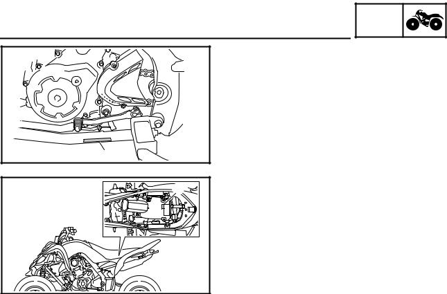
VEHICLE IDENTIFICATION NUMBER
The vehicle identification number 1 is stamped into the left side of the frame.
EBS00011
MODEL LABEL
The model label 1 is affixed to the air filter case cover. This information will be needed to order spare parts.
1 - 1
GEN
FEATURES INFO
EAS20170
FEATURES
OUTLINE OF THE FI SYSTEM
The main function of a fuel supply system is to provide fuel to the combustion chamber at the optimum air-fuel ratio in accordance with the engine operating conditions and the atmospheric temperature. In the conventional carburetor system, the air-fuel ratio of the mixture that is supplied to the combustion chamber is created by the volume of the intake air and the fuel that is metered by the jet used in the respective carburetor.
Despite the same volume of intake air, the fuel volume requirement varies with the engine operating conditions, such as acceleration, deceleration, or operating under a heavy load. Carburetors that meter the fuel through the use of jets have been provided with various auxiliary devices, so that an optimum air-fuel ratio can be achieved to accommodate the constant changes in the operating conditions of the engine.
As the requirements for the engine to deliver more performance and cleaner exhaust gases increase, it becomes necessary to control the air-fuel ratio in a more precise and finely tuned manner. To accommodate this need, this model has adopted an electronically controlled fuel injection (FI) system, in place of the conventional carburetor system. This system can achieve an optimum air-fuel ratio required by the engine at all times by using a microprocessor that regulates the fuel injection volume according to the engine operating conditions detected by various sensors.
The adoption of the FI system has resulted in a highly precise fuel supply, improved engine response, better fuel economy, and reduced exhaust emissions.
1 2 |
3 4 5 6 7 8 9 0 A B |
||||||
|
|
|
|
|
|
|
|
|
|
|
|
|
|
|
|
|
|
|
|
|
|
|
|
|
|
|
|
|
|
|
|
1 |
H G F E |
D C |
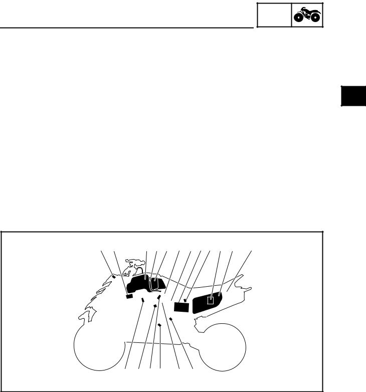
1 Engine trouble warning light |
0 ECU (electronic control unit) |
2 Ignition coil |
A Air filter case |
3 Fuel tank |
B Relay unit (fuel pump relay) |
4 Fuel hose |
C Speed sensor |
5 Fuel pump |
D Throttle position sensor |
6 Intake air pressure sensor |
E Crankshaft position sensor |
7 Lean angle sensor |
F Fuel injector |
8 Battery |
G Coolant temperature sensor |
9 Intake air temperature sensor |
H Spark plug |
1 - 2

FEATURES
FI SYSTEM
GEN  INFO
INFO 


The fuel pump delivers fuel to the fuel injector via the fuel filter. The pressure regulator maintains the fuel pressure that is applied to the fuel injector at only 324 kPa (3.24 kg/cm2, 46.1 psi). Accordingly, when the energizing signal from the ECU energizes the fuel injector, the fuel passage opens, causing the fuel to be injected into the intake manifold only during the time the passage remains open. Therefore, the longer the length of time the fuel injector is energized (injection duration), the greater the volume of fuel that is supplied. Conversely, the shorter the length of time the fuel injector is energized (injection duration), the lesser the volume of fuel that is supplied.
The injection duration and the injection timing are controlled by the ECU. Signals that are input from the throttle position sensor, crankshaft position sensor, intake air pressure sensor, intake air temperature sensor, coolant temperature sensor and speed sensor enable the ECU to determine the injection duration. The injection timing is determined through the signals from the crankshaft position sensor. As a result, the volume of fuel that is required by the engine can be supplied at all times in accordance with the driving conditions.
Illustration is for reference only.
|
Ê |
B |
|
4 |
|
|
|
|
1 |
2 |
|
|
|
|
È |
|
|
|
|
3 |
A |
|
|
0 |
|
|
É |
|
|
9 |
|
|
|
8 |
|
7 |
|
5 |
|
|
6 |
1 Fuel pump |
9 Intake air temperature sensor |
2 Fuel injector |
0 Air filter case |
3 Ignition coil |
A Throttle position sensor |
4 ECU (electronic control unit) |
B Speed sensor |
5 Coolant temperature sensor |
|
6 Crankshaft position sensor |
È Fuel system |
7 Intake air pressure sensor |
É Air system |
8 Throttle body |
Ê Control system |
1 - 3

FEATURES
SELF-ADJUSTING PARKING BRAKE MECHANISM
GEN  INFO
INFO 


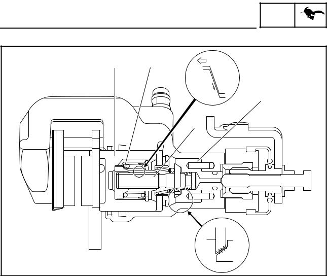
Usually, for vehicles equipped with a parking brake that must be adjusted manually, it is necessary to adjust the adjusting bolt 5 to achieve the proper clearance between the brake caliper piston 7 and the adjusting bolt 5.
This adjustment procedure is unnecessary for vehicles equipped with a self-adjusting parking brake mechanism. The proper clearance is automatically maintained at all times, ensuring stable braking performance when parking the vehicle.
|
|
|
1 |
|
|
|
2 |
|
|
|
3 |
7 |
6 |
5 |
4 |
1 Parking brake arm |
5 Adjusting bolt |
2 Parking brake shaft |
6 Nut |
3 Adjusting bolt |
7 Brake caliper piston |
4 Adjusting bolt sleeve |
|
1 - 4
FEATURES
Parking Brake Operation
GEN  INFO
INFO 


|
|
1 |
|
|
2 |
|
|
3 |
6 |
5 |
4 |
1 Parking brake arm |
4 Adjusting bolt sleeve |
2 Parking brake shaft |
5 Brake caliper piston |
3 Adjusting bolt |
6 Brake pad |
When the parking brake is operated, the parking brake cable turns the parking brake arm 1. The rotation of the parking brake arm is changed to axial thrust in the parking brake shaft 2 and the adjusting bolt 3 is pushed against the adjusting bolt sleeve 4.
When the adjusting bolt sleeve receives the force, the dark shaded area in the above illustration is pushed and the brake pad 6 is pushed against the brake disc.
When the brake pad wears, the clearance between the brake caliper piston 5 and the brake pad becomes larger and the force applied to the brake pad becomes weaker.
If this occurs, the self-adjusting parking brake mechanism adjusts automatically to achieve the proper clearance.
1 - 5
FEATURES
Parking Brake Operation
GEN  INFO
INFO 


1 |
2 |
È |
|
||
|
|
É |
|
|
4 |
|
|
3 |
|
|
Ê |
1 Brake caliper piston |
3 Adjusting bolt |
2 Nut |
4 Adjusting bolt sleeve |
When the brake pedal is operated, the brake fluid pressure in the master cylinder increases and the brake caliper piston 1 and the nut 2 are pushed.
When there is proper clearance between the brake caliper piston and the brake pad, no other parts move because the movement of the brake caliper piston and the nut is absorbed by the backlash of the threads of the nut and the adjusting bolt 3.
When the movement of the nut is greater than the backlash between the nut and the adjusting bolt, the parking brake adjusts automatically.
The amount of the adjustment varies with brake fluid pressure. Operating the parking brake makes no adjustment.
The adjustment operation is as follows.
1.When the brake pedal is operated, the brake fluid pressure increases and the brake caliper piston and the nut move.
2.When the movement of the brake caliper piston and the nut is greater than the backlash of the threads of the nut and the adjusting bolt, the force È will be required to pull the adjusting bolt. The force to pull the adjusting bolt will be turned into the rotation torque É by the shape of the threads of the nut and the adjusting bolt.
3.At this time, the clutch torque Ê between the adjusting bolt and the adjusting bolt sleeve 4 will decrease depending on the force required to pull the adjusting bolt.
When the rotation torque exceeds the clutch torque, the adjusting bolt rotates and the clearance between the brake caliper piston and the brake pad decreases by the movement of the threads of the nut and the adjusting bolt.
1 - 6

IMPORTANT INFORMATION
EBS00013
GEN  INFO
INFO 


IMPORTANT INFORMATION
PREPARATION FOR REMOVAL AND
DISASSEMBLY
1.Before removal and disassembly remove all dirt, mud, dust and foreign material.
2.Use only the proper tools and cleaning equipment.
Refer to “SPECIAL TOOLS”.
3.When disassembling always keep mated parts together. This includes gears, cylinders, pistons and other parts that have been “mated” through normal wear. Mated parts must always be reused or replaced as an assembly.
4.During disassembly, clean all of the parts and place them in trays in the order of disassembly. This will speed up assembly and allow for the correct installation of all parts.
5.Keep all parts away from any source of fire.
EBS00014
REPLACEMENT PARTS
1.Use only genuine Yamaha parts for all replacements. Use oil and grease recommended by Yamaha for all lubrication jobs. Other brands may be similar in function and appearance, but inferior in quality.
EBS00015
GASKETS, OIL SEALS AND O-RINGS
1.When overhauling the engine, replace all gaskets, seals and O-rings. All gasket surfaces, oil seal lips and O-rings must be cleaned.
2.During reassembly properly oil all mating parts and bearings, and lubricate the oil seal lips with grease.
1 - 7

IMPORTANT INFORMATION
EBS00016
GEN  INFO
INFO 


LOCK WASHERS/PLATES AND COTTER PINS
After removal, replace all lock washers/plates 1 and cotter pins. After the bolt or nut has been tightened to specification, bend the lock tabs along a flat of the bolt or nut.
EBS00017
BEARINGS AND OIL SEALS
Install bearings and oil seals so that the manufacturer’s marks or numbers are visible. When installing oil seals, lubricate the oil seal lips with a light coat of lithium-soap-based grease. Oil bearings liberally when installing, if appropriate.
1 Oil seal
CAUTION:
Do not spin the bearing with compressed air because this will damage the bearing surfaces.
1 Bearing
EBS00018
CIRCLIPS
Before reassembly, check all circlips carefully and replace damaged or distorted circlips. Always replace piston pin clips after one use. When installing a circlip 1, make sure the sharp-edged corner 2 is positioned opposite the thrust 3 that the circlip receives.
4 Shaft
1 - 8
GEN
IMPORTANT INFORMATION INFO
EBS00019
CHECKING THE CONNECTIONS
Check the leads, couplers, and connectors for stains, rust, moisture, etc.
1.Disconnect:
•lead
•coupler
•connector
2.Check:
•lead
•coupler
•connector
Moisture → Dry with an air blower. Rust/stains → Connect and disconnect sev-
eral times.
3.Check:
•all connections
Loose connection → Connect properly.
NOTE:
If the pin 1 on the terminal is flattened, bend it up.
4.Connect:
•lead
•coupler
•connector
NOTE:
Make sure all connections are tight.
5.Check:
•continuity (with the pocket tester)
Pocket tester 90890-03112
Analog pocket tester YU-03112-C
NOTE:
•If there is no continuity, clean the terminals.
•When checking the wire harness, perform steps (1) to (3).
•As a quick remedy, use a contact revitalizer available at most part stores.
1 - 9

SPECIAL TOOLS
EBS00021
SPECIAL TOOLS
GEN  INFO
INFO 


The following special tools are necessary for complete and accurate tune-up and assembly. Use only the appropriate special tools; this will help prevent damage caused by the use of inappropriate tools or improvised techniques. Special tools may differ by shape and part number from country to country. In such a case, two types are provided.
When placing an order, refer to the list provided below to avoid any mistakes. For US and CDN
P/N. YM-, YU-, YS-, YK-, ACCExcept for US and CDN
P/N. 90890-
Tool No. |
Tool name/Function |
Illustration |
|
|
|
|
Slide hammer bolt |
|
|
Slide hammer bolt (6 mm) |
|
90890-01083 |
|
|
YU-01083-1 |
|
|
|
This tool is used to remove the rocker arm |
|
|
shaft. |
|
|
|
|
|
Weight |
|
90890-01084 |
|
|
YU-01083-3 |
|
|
|
This tool is used to remove the rocker arm |
|
|
shaft. |
|
|
|
|
|
Crankcase separating tool |
|
|
Crankcase separator |
|
90890-01135 |
|
|
YU-01135-B |
|
|
|
This tool is used to separate the crank- |
|
|
case. |
|
|
|
|
|
Ring nut wrench |
|
|
Spanner wrench |
|
90890-01268 |
|
|
YU-01268 |
|
|
|
This tool is used to loosen or tighten the |
|
|
rear shock absorber locknuts. |
|
|
|
|
|
Crankshaft installer pot |
|
90890-01274 |
Installer pot |
|
Pot installer |
|
|
YU-90058 |
|
|
|
|
|
YU-90059 |
|
|
|
This tool is used to install the crankshaft. |
|
|
|
|
|
Crankshaft installer bolt |
|
|
Bolt |
|
90890-01275 |
|
|
YU-90060 |
|
|
|
This tool is used to install the crankshaft. |
|
|
|
|
1 - 10

|
|
|
|
|
|
|
|
SPECIAL TOOLS |
|
|
GEN |
|
|
|
|
|
INFO |
|
||
|
|
|
|
|
|
|
|
|
|
||||
Tool No. |
Tool name/Function |
Illustration |
||||
|
|
|
|
|
|
|
|
Adapter (M16) |
|
|
|
|
|
|
Adapter #13 |
|
|
|
|
|
90890-04130 |
|
|
|
|
|
|
YM-04059 |
|
|
|
|
|
|
|
This tool is used to install the crankshaft. |
|
|
|
|
|
|
|
|
|
|
|
|
|
Spacer (crankshaft installer) |
|
|
|
|
|
|
Pot spacer |
|
|
|
|
|
90890-04081 |
|
|
|
|
|
|
YM-91044 |
|
|
|
|
|
|
|
This tool is used to install the crankshaft. |
|
|
|
|
|
|
|
|
|
|
|
|
|
Piston pin puller set |
|
|
|
|
|
|
Piston pin puller |
|
|
|
|
|
90890-01304 |
|
|
|
|
|
|
YU-01304 |
|
|
|
|
|
|
|
This tool is used to remove the piston pin. |
|
|
|
|
|
|
|
|
|
|
|
|
|
Tappet adjusting tool |
|
|
|
|
|
|
Valve adjuster (3 mm & 4 mm) |
|
|
|
|
|
90890-01311 |
|
|
|
|
|
|
YM-08035-A |
|
|
|
|
|
|
|
This tool is necessary for adjusting the |
|
|
|
|
|
|
valve clearance. |
|
|
|
|
|
|
|
|
|
|
|
|
|
Radiator cap tester |
|
|
|
|
|
|
Radiator pressure tester |
|
|
|
|
|
90890-01325 |
|
|
|
|
|
|
YU-24460-01 |
|
|
|
|
|
|
|
This tool is used to check the cooling sys- |
|
|
|
|
|
|
tem. |
|
|
|
|
|
|
|
|
|
|
|
|
|
Radiator cap tester adapter |
|
|
|
|
|
|
Radiator pressure tester adapter |
|
|
|
|
|
90890-01352 |
|
|
|
|
|
|
YU-33984 |
|
|
|
|
|
|
|
This tool is used to check the cooling sys- |
|
|
|
|
|
|
tem. |
|
|
|
|
|
|
|
|
|
|
|
|
|
Damper rod holder (30 mm) |
|
|
|
|
|
90890-01327 |
|
|
|
|
|
|
YM-01327 |
|
|
|
|
|
|
|
This tool is needed to loosen and tighten |
|
|
|
|
|
|
the steering stem bearing retainer. |
|
|
|
|
|
|
|
|
|
|
|
|
|
Flywheel puller |
|
|
|
|
|
90890-01404 YM-01404
This tool is used to remove the A.C.magneto rotor.
1 - 11
|
|
|
|
|
|
|
|
SPECIAL TOOLS |
|
|
GEN |
|
|
|
|
|
INFO |
|
||
|
|
|
|
|
|
|
|
|
|
||||
Tool No. |
Tool name/Function |
Illustration |
||||
|
|
|
|
|
|
|
|
Steering nut wrench |
|
|
|
|
|
|
Spanner wrench |
|
|
|
|
|
90890-01443 |
|
|
|
|
|
|
YU-33975 |
This tool is needed to loosen and tighten |
|
|
|
|
|
|
the front shock absorber and rear shock |
|
|
|
|
|
|
absorber locknuts. |
|
|
|
|
|
|
|
|
|
|
|
|
|
Ball joint remover |
|
|
|
|
|
90890-01474 |
|
|
|
|
|
|
YM-01474 |
|
|
|
|
|
|
|
This tool is used to remove or install the |
|
|
|
|
|
|
ball joints. |
|
|
|
|
|
|
|
|
|
|
|
|
|
Ball joint remover attachment set |
|
|
|
|
|
|
Ball joint adapter set |
|
|
|
|
|
90890-01480 |
|
|
|
|
|
|
YM-01480 |
|
|
|
|
|
|
|
These tools are used to remove or install |
|
|
|
|
|
|
the ball joints. |
|
|
|
|
|
|
|
|
|
|
|
|
|
Rear axle nut wrench (46 mm) |
|
|
|
|
|
|
Axle nut wrench (46 mm) |
|
|
|
|
|
90890-01498 |
|
|
|
|
|
|
YM-37134 |
|
|
|
|
|
|
|
This tool is needed to loosen or tighten the |
|
|
|
|
|
|
rear axle nut. |
|
|
|
|
|
|
|
|
|
|
|
|
|
Sheave holder |
|
|
|
|
|
|
Primary clutch holder |
|
|
|
|
|
90890-01701 |
|
|
|
|
|
|
YS-01880-A |
This tool is used to hold the A.C. magneto |
|
|
|
|
|
|
rotor when loosen or tighten the A.C. mag- |
|
|
|
|
|
|
neto rotor nut. |
|
|
|
|
|
|
|
|
|
|
|
|
|
Thickness gauge |
|
|
|
|
|
|
Narrow gauge set |
|
|
|
|
|
90890-03079 |
|
|
|
|
|
|
YM-34483 |
|
|
|
|
|
|
|
This tool is used to measure the valve |
|
|
|
|
|
|
clearance. |
|
|
|
|
|
|
|
|
|
|
|
|
|
Compression gauge |
|
|
|
|
|
|
Engine compression tester |
|
|
|
|
|
90890-03081 |
|
|
|
|
|
|
YU-33223 |
|
|
|
|
|
|
|
This tool is used to measure engine com- |
|
|
|
|
|
|
pression. |
|
|
|
|
|
|
|
|
|
|
|
|
|
Extension |
|
|
|
|
|
90890-04082
This tool is used to measure engine compression.
1 - 12

|
|
|
|
|
|
|
|
SPECIAL TOOLS |
|
GEN |
|
|
|
|
INFO |
|
|
|
|
|
|
|
|
|
|
|
|||
Tool No. |
Tool name/Function |
Illustration |
|||
Pocket tester Analog pocket tester
90890-03112 YU-03112-C
This instrument is needed for checking the electrical system.
Timing light
Inductive clamp timing light
90890-03141 YU-03141
This tool is necessary for checking ignition timing.
Pressure gauge
90890-03153 YU-03153
This tool is used to measure fuel pressure.
Fuel pressure adapter
90890-03176 YM-03176
This tool is used to measure fuel pressure.
Digital circuit tester
Model 88 Multimeter with tachometer
90890-03174 YU-A1927
This tool is used to check the electrical system.
FI diagnostic tool
90890-03182 YU-03182
This tool is used to check the diagnosis.
Valve spring compressor
90890-04019 YM-04019
This tool is needed to remove and install the valve assemblies.
Valve spring compressor attachment Valve spring compressor adapter (26 mm)
90890-01243 YM-01253-1
This tool is needed to remove and install the valve assemblies.
1 - 13

|
|
|
|
|
|
|
|
SPECIAL TOOLS |
|
|
GEN |
|
|
|
|
|
INFO |
|
||
|
|
|
|
|
|
|
|
|
|
||||
Tool No. |
Tool name/Function |
Illustration |
||||
|
|
|
|
|
|
|
|
Middle driven shaft bearing driver |
|
|
|
|
|
|
Bearing driver (40 mm) |
|
|
|
|
|
90890-04058 |
|
|
|
|
|
|
YM-04058 |
|
|
|
|
|
|
|
This tool is used to install the water pump |
|
|
|
|
|
|
seal. |
|
|
|
|
|
|
|
|
|
|
|
|
|
Mechanical seal installer |
|
|
|
|
|
|
Water pump seal installer |
|
|
|
|
|
90890-04132 |
|
|
|
|
|
|
YM-33221-A |
|
|
|
|
|
|
|
This tool is used to install the water pump |
|
|
|
|
|
|
seal. |
|
|
|
|
|
|
|
|
|
|
|
|
|
Valve guide remover (ø6) |
|
|
|
|
|
|
Valve guide remover (6.0 mm) |
|
|
|
|
|
90890-04064 |
|
|
|
|
|
|
YM-4064-A |
|
|
|
|
|
|
|
This tool is needed to remove and install |
|
|
|
|
|
|
the valve guides. |
|
|
|
|
|
|
|
|
|
|
|
|
|
Valve guide installer (ø6) |
|
|
|
|
|
|
Valve guide installer (6.0 mm) |
|
|
|
|
|
90890-04065 |
|
|
|
|
|
|
YM-4065-A |
|
|
|
|
|
|
|
This tool is needed to install the valve |
|
|
|
|
|
|
guides. |
|
|
|
|
|
|
|
|
|
|
|
|
|
Valve guide reamer (ø6) |
|
|
|
|
|
|
Valve guide reamer (6.0 mm) |
|
|
|
|
|
90890-04066 |
|
|
|
|
|
|
YM-04066 |
|
|
|
|
|
|
|
This tool is needed to rebore the new |
|
|
|
|
|
|
valve guides. |
|
|
|
|
|
|
|
|
|
|
|
|
|
Universal clutch holder |
|
|
|
|
|
90890-04086 |
|
|
|
|
|
|
YM-91042 |
This tool is needed to hold the clutch boss |
|
|
|
|
|
|
when removing or installing the clutch |
|
|
|
|
|
|
boss nut. |
|
|
|
|
|
|
|
|
|
|
|
|
|
Ignition checker |
|
|
|
|
|
|
Opama pet-4000 spark checker |
|
|
|
|
|
90890-06754 |
|
|
|
|
|
|
YM-34487 |
|
|
|
|
|
|
|
This tool is used to check the ignition sys- |
|
|
|
|
|
|
tem components. |
|
|
|
|
|
|
|
|
|
|
|
|
|
Digital tachometer |
|
|
|
|
|
90890-06760 YU-39951-B
This tool is needed to observe engine rpm.
1 - 14
Loading...