


2005
TDM900A(T)
5PS1-AE4
SUPPLEMENTARY SERVICE MANUAL

FOREWORD
This Supplementary Service Manual has been prepared to introduce new service and data for the TDM900A(T) 2005. For complete service information procedures it is necessary to use this Supplementary Service Manual together with the following manual.
TDM900(N) 2001 SERVICE MANUAL: 5PS1-AE1
TDM900(R) 2003 SUPPLEMENTARY SERVICE MANUAL: 5PS1-AE2
TDM900(S) 2004 SUPPLEMENTARY SERVICE MANUAL: 5PS1-AE3
TDM900A(T) 2005
SUPPLEMENTARY
SERVICE MANUAL ©2004 by Yamaha Motor Co., Ltd.
First Edition, December 2004 All rights reserved.
Any reproduction or unauthorized use without the written permission of Yamaha Motor Co., Ltd.
is expressly prohibited.
EAS00002
NOTICE
This manual was produced by the Yamaha Motor Company, Ltd. primarily for use by Yamaha dealers and their qualified mechanics. It is not possible to include all the knowledge of a mechanic in one manual. Therefore, anyone who uses this book to perform maintenance and repairs on Yamaha vehicles should have a basic understanding of mechanics and the techniques to repair these types of vehicles. Repair and maintenance work attempted by anyone without this knowledge is likely to render the vehicle unsafe and unfit for use.
Yamaha Motor Company, Ltd. is continually striving to improve all its models. Modifications and significant changes in specifications or procedures will be forwarded to all authorized Yamaha dealers and will appear in future editions of this manual where applicable.
NOTE:
Designs and specifications are subject to change without notice.
EAS00004
IMPORTANT INFORMATION
Particularly important information is distinguished in this manual by the following.
|
|
The Safety Alert Symbol means ATTENTION! BECOME ALERT! YOUR |
||
|
|
SAFETY IS INVOLVED! |
||
WARNING |
Failure to follow WARNING instructions could result in severe injury or death |
|||
|
|
|||
to the motorcycle operator, a bystander or a person checking or repairing the |
||||
|
|
|||
|
|
motorcycle. |
||
|
|
A CAUTION indicates special precautions that must be taken to avoid dam- |
||
CAUTION: |
|
|||
|
age to the motorcycle. |
|||
|
|
|||
NOTE: |
A NOTE provides key information to make procedures easier or clearer. |
|||

EAS00007
HOW TO USE THIS MANUAL
This manual is intended as a handy, easy-to-read reference book for the mechanic. Comprehensive explanations of all installation, removal, disassembly, assembly, repair and check procedures are laid out with the individual steps in sequential order.
 The manual is divided into chapters. An abbreviation and symbol in the upper right corner of each page indicate the current chapter.
Refer to “SYMBOLS”.
 Each chapter is divided into sections. The current section title is shown at the top of each page, except in Chapter 3 (“PERIODIC CHECKS AND ADJUSTMENTS”), where the sub-section title(s) appears.
 Sub-section titles appear in smaller print than the section title.
 To help identify parts and clarify procedure steps, there are exploded diagrams at the start of each removal and disassembly section.
 Numbers are given in the order of the jobs in the exploded diagram. A circled number indicates a disassembly step.
 Symbols indicate parts to be lubricated or replaced.
Refer to “SYMBOLS”.
 A job instruction chart accompanies the exploded diagram, providing the order of jobs, names of parts, notes in jobs, etc.
 Jobs requiring more information (such as special tools and technical data) are described sequentially.

EAS00008
SYMBOLS
The following symbols are not relevant to every vehicle.
Symbols  to
to  indicate the subject of each chapter.
 General information
 Specifications
 Periodic checks and adjustments
 Chassis
 Engine
 Cooling system
 Fuel injection system
 Electrical system
  Troubleshooting
Symbols  to
to  indicate the following.
 Serviceable with engine mounted
 Filling fluid
 Lubricant
 Special tool
 Tightening torque
 Wear limit, clearance
 Engine speed
  Electrical data
Symbols  to
to  in the exploded diagrams indicate the types of lubricants and lubrication points.
 Engine oil
 Gear oil
 Molybdenum-disulfide oil
 Wheel-bearing grease
 Lithium-soap- based grease
 Molybdenum-disulfide grease
Symbols  to
to  in the exploded diagrams indicate the following.
 Apply locking agent (LOCTITE®)
  Replace the part

CONTENTS
GENERAL INFORMATION
FEATURES . . . . . . . . . . . . . . . . . . . . . . . . . . . . . . . . . . . . . . . . . . . . . 1 INSTRUMENT PANEL. . . . . . . . . . . . . . . . . . . . . . . . . . . . . . . . . . 1 SPECIAL TOOLS . . . . . . . . . . . . . . . . . . . . . . . . . . . . . . . . . . . . . . . . 4
SPECIFICATIONS
GENERAL SPECIFICATIONS . . . . . . . . . . . . . . . . . . . . . . . . . . . . . . 5 ENGINE SPECIFICATIONS . . . . . . . . . . . . . . . . . . . . . . . . . . . . . . . . 5 CHASSIS SPECIFICATIONS . . . . . . . . . . . . . . . . . . . . . . . . . . . . . . . 5 ELECTRICAL SPECIFICATIONS. . . . . . . . . . . . . . . . . . . . . . . . . . . . 6 TIGHTENING TORQUES . . . . . . . . . . . . . . . . . . . . . . . . . . . . . . . . . . 7
CHASSIS TIGHTENING TORQUES . . . . . . . . . . . . . . . . . . . . . . . 7 CABLE ROUTING. . . . . . . . . . . . . . . . . . . . . . . . . . . . . . . . . . . . . . . . 8 SWINGARM AND DRIVE CHAIN . . . . . . . . . . . . . . . . . . . . . . . . . . . . 28
CHECKING THE DRIVE CHAIN . . . . . . . . . . . . . . . . . . . . . . . . . . 28 ANTI-LOCK BRAKE SYSTEM (ABS) . . . . . . . . . . . . . . . . . . . . . . . . 30 ABS OUTLINE . . . . . . . . . . . . . . . . . . . . . . . . . . . . . . . . . . . . . . . . 30 ABS . . . . . . . . . . . . . . . . . . . . . . . . . . . . . . . . . . . . . . . . . . . . . . . . 31 ABS COMPONENTS . . . . . . . . . . . . . . . . . . . . . . . . . . . . . . . . . . . 49 FRONT WHEEL SENSOR AND SENSOR ROTOR . . . . . . . . . . . 50 REAR WHEEL SENSOR AND SENSOR ROTOR . . . . . . . . . . . . 54 HYDRAULIC UNIT. . . . . . . . . . . . . . . . . . . . . . . . . . . . . . . . . . . . . 57 HYDRAULIC ABS . . . . . . . . . . . . . . . . . . . . . . . . . . . . . . . . . . . . . 64 CHECKING THE RESERVOIR TANK FLUID LEVEL . . . . . . . . . . 73 TRIAL RUN . . . . . . . . . . . . . . . . . . . . . . . . . . . . . . . . . . . . . . . . . . 73
ELECTRICAL
ELECTRICAL COMPONENTS . . . . . . . . . . . . . . . . . . . . . . . . . . . . . . 74 CHECKING THE SWITCHES . . . . . . . . . . . . . . . . . . . . . . . . . . . . . . . 76 ELECTRIC STARTING SYSTEM . . . . . . . . . . . . . . . . . . . . . . . . . . . . 77 CIRCUIT DIAGRAM. . . . . . . . . . . . . . . . . . . . . . . . . . . . . . . . . . . . 77 STARTING CIRCUIT CUT-OFF SYSTEM OPERATION . . . . . . . 78 TROUBLESHOOTING. . . . . . . . . . . . . . . . . . . . . . . . . . . . . . . . . . 79 SIGNALING SYSTEM. . . . . . . . . . . . . . . . . . . . . . . . . . . . . . . . . . . . . 83 CIRCUIT DIAGRAM. . . . . . . . . . . . . . . . . . . . . . . . . . . . . . . . . . . . 83 TROUBLESHOOTING. . . . . . . . . . . . . . . . . . . . . . . . . . . . . . . . . . 85 CHECKING THE SIGNAL SYSTEM . . . . . . . . . . . . . . . . . . . . . . . 86

ANTI-LOCK BRAKE SYSTEM (ABS) . . . . . . . . . . . . . . . . . . . . . . . . 94 CIRCUIT DIAGRAM. . . . . . . . . . . . . . . . . . . . . . . . . . . . . . . . . . . . 94 ABS COMPONENTS . . . . . . . . . . . . . . . . . . . . . . . . . . . . . . . . . . . 96 ABS CONNECTOR LOCATION CHART. . . . . . . . . . . . . . . . . . . . 97 ECU (ABS) AND FAIL-SAFE RELAY . . . . . . . . . . . . . . . . . . . . . . 98 TROUBLESHOOTING. . . . . . . . . . . . . . . . . . . . . . . . . . . . . . . . . . 103 CHECKING THE ANTI-LOCK BRAKE SYSTEM. . . . . . . . . . . . . . 104 TROUBLESHOOTING BY THE SELF DIAGNOSIS . . . . . . . . . . . 107 MALFUNCTION CHECK BY THE ABS SELF DIAGNOSIS
(PAST MALFUNCTION) . . . . . . . . . . . . . . . . . . . . . . . . . . . . . . . . 107 MALFUNCTION CHECK BY THE ABS SELF DIAGNOSIS
(PRESENT MALFUNCTION). . . . . . . . . . . . . . . . . . . . . . . . . . . . . 108 DELETING THE MALFUNCTION CODE . . . . . . . . . . . . . . . . . . . 120
TROUBLESHOOTING
ANTI-LOCK BRAKE SYSTEM (ABS) . . . . . . . . . . . . . . . . . . . . . . . . 122 ABS TROUBLESHOOTING OUTLINE . . . . . . . . . . . . . . . . . . . . . 122 BASIC INSTRUCTION FOR TROUBLESHOOTING. . . . . . . . . . . 123 BASIC PROCESS FOR TROUBLESHOOTING . . . . . . . . . . . . . . 124
TROUBLESHOOTING AT THE ABS WARNING LIGHT . . . . . . . . . . 125 ONLY THE ABS WARNING LIGHT DOES NOT COME ON. . . . . 125 ALL INDICATORS DO NOT COME ON. . . . . . . . . . . . . . . . . . . . . 125 ABS WARNING LIGHT CONTINUES TO FLASHES. . . . . . . . . . . 125 ABS WARNING LIGHT FLASHES EVERY 0.5 SECONDS. . . . . . 125 ABS WARNING LIGHT CONTINUES TO COME ON. . . . . . . . . . 125
TDM900A(T) 2005 WIRING DIAGRAM
GEN
FEATURES INFO
GENERAL INFORMATION
FEATURES
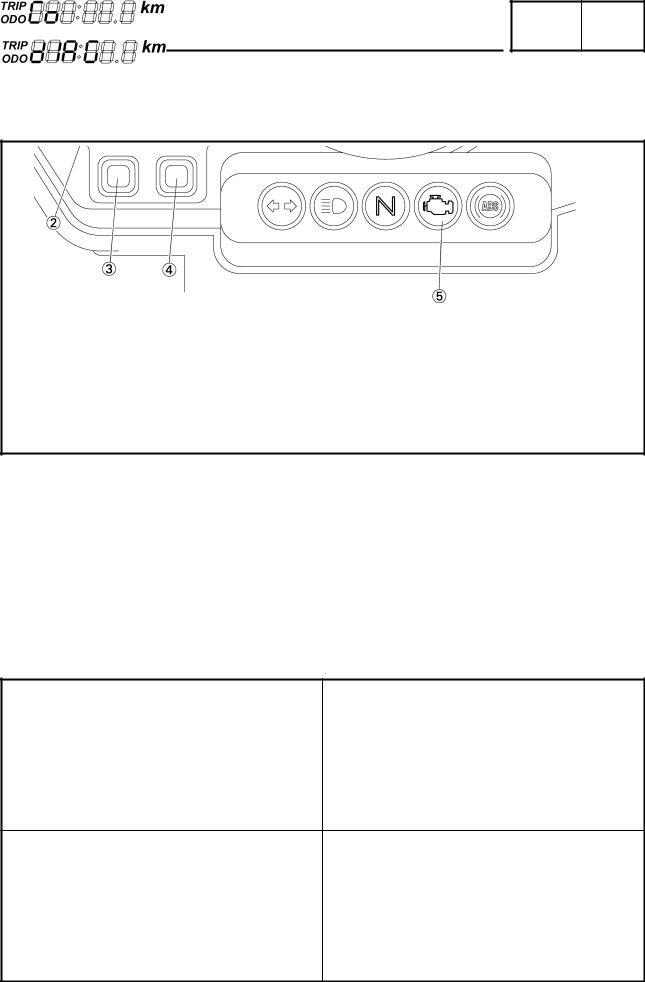
INSTRUMENT PANEL
Clock
TRIP/ODO meter
SELECT button
RESET button
Engine trouble warning light
Function indication
The indications of the self-diagnosis function can be checked and inspection operations can be performed through the use of the multi-function meter on the instrument panel.
Based on the signals received from the sensors, the ECU inputs the signals into the multi-function meter. Then, the conditions of the sensors appear on the clock and trip/odometer display of the multi-function meter.
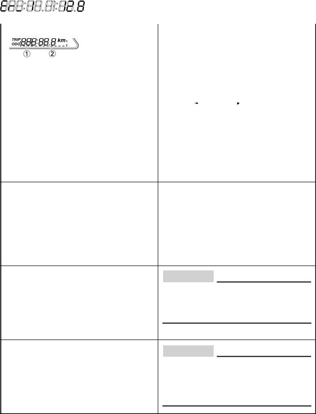
NORMAL MODE |
Speed meter |
|
Fuel meter |
|
(The symbol “ ” blinks when the gasoline is |
|
almost empty) |
|
Trip/odometer display |
|
Clock display |
CO ADJUSTMENT/DIAGNOSTIC |
Temporary selection display for CO/DIAG. |
MONITORING SELECTION MODE |
CO: |
|
|
|
DIAG: |
1
|
|
FEATURES |
|
|
GEN |
|
||||
|
|
|
|
INFO |
|
|||||
|
|
|
|
|
|
|
|
|
|
|
CO ADJUSTMENT MODE |
Cylinder identification |
|
|
|
|
|||||
|
For #1 |
|
|
For #2 |
|
|
|
|
||
|
CO data |
|
|
|
|
|
|
|
|
|
|
Example: |
|
|
|
|
|||||
|
lean |
|
|
|
|
|
rich |
|||
|
–128 |
|
|
0 |
|
|
128 |
|
||
|
|
|
|
|||||||
|
|
|
|
|
|
|||||
DIAGNOSTIC MONITORING MODE |
Diagnostic monitoring code |
|||||||||
|
Example: code “01” |
|
|
|
|
|||||
 Monitoring data
WHEN THE COMMUNICATION ERROR |
Error code |
OCCURRED BETWEEN ECU AND METER: |
Example: When the error code is “Er-1” |
For details of error codes, refer to “FAIL-SAFE ACTION TABLE” in chapter 7. (Manual No.: 5PS1-AE1)
CAUTION:
If the display  shown in the illustration to the left appears, the multi-function display is malfunctioning. Replace the meter assembly.
CAUTION:
If the fuel meter does not display the fuel level, but repeatedly flashes as shown in the illustration, the fuel level monitoring system is malfunctioning. Check the fuel sender and the electrical circuit.
2
FEATURES
CO adjustment and diagnostic monitoring mode
GEN INFO
Mode Selection
Normal mode
Turn “ON” the main switch
•The self-diagnostic function starts a system check
System normal
Normal meter display
Malfunction detection fault number appears on the clock LCD.
The engine trouble warning light illuminates.
CO/DIAG mode
1.While keeping both the SELECT and RESET buttons pressed, turn “ON” the
main switch. Keep the buttons pressed for 8 seconds or more.
•All the segments are “OFF” expect the clock and the trip LCD.
•“DIAG” appears on the clock LCD.
Switching between CO adjustment mode and DIAG mode
1.Press the SELECT button in order to switch the display to “CO” or “DIAG”.
2.Simultaneously press the SELECT and RESET buttons for 2 seconds or more to select an item.
CO adjustment mode |
|
Diagnosis monitoring mode |
Refer to “CO adjustment” in chapter 3. |
|
Refer to “TROUBLESHOOTING” in chapter |
(Manual No.: 5PS1-AE1) |
|
7. |
|
|
(Manual No.: 5PS1-AE1) |
|
||
|
|
|
|
|
(The engine cannot be started in this mode) |
3
GEN
SPECIAL TOOLS INFO
EB104000
SPECIAL TOOLS
The following special tools are necessary for complete and accurate tune-up and assembly.
Use only the appropriate special tools as this will help prevent damage caused by the use of inappropriate tools or improvised techniques.
When placing an order, refer to the list provided below to avoid any mistakes.
Tool No. |
Tool name/Function |
Illustration |
|
|
|
|
Test coupler adaptor |
|
90890-03149 |
|
|
|
This tool is used to check the ABS diagnosis. |
|
|
|
|
4

GENERAL SPECIFICATIONS/ |
|
SPEC |
|
ENGINE SPECIFICATIONS/CHASSIS SPECIFICATIONS |
|
|
|
|
|
|
|
|
|
|
|
SPECIFICATIONS |
|
|
|
GENERAL SPECIFICATIONS |
|
|
|
Item |
Standard |
Limit |
|
|
|
Model code |
2B01 (EUR) |
••• |
|
|
|
Weight |
|
|
Wet (with oil and a full fuel tank) |
224 kg (494 lb) |
••• |
Dry (without oil and fuel) |
193 kg (426 lb) |
••• |
Maximum load (total of cargo, rider, |
200 kg (441 lb) |
••• |
passenger, and accessories) |
|
|
|
|
|
ENGINE SPECIFICATIONS
Item |
Standard |
Limit |
|
|
|
Throttle bodies |
|
|
Model (manufacturer) × quantity |
38EIS (MIKUNI) × 2 |
••• |
ID mark |
5PS1 11 |
••• |
|
|
|
CHASSIS SPECIFICATIONS
Item |
Standard |
Limit |
|
|
|
Front tire |
|
|
Tire type |
Tubeless |
••• |
Size |
120/70ZR 18M/C (59W) |
••• |
Model (manufacturer) |
D220FSTJ (DUNLOP) |
••• |
Tire pressure (cold) |
225 kPa (2.25 kgf/cm2, 2.25 bar, 32 psi) |
|
0 ~ 90 kg |
••• |
|
90 ~ 200 kg |
225 kPa (2.25 kgf/cm2, 2.25 bar, 32 psi) |
••• |
High-speed riding |
225 kPa (2.25 kgf/cm2, 2.25 bar, 32 psi) |
••• |
Min. tire tread depth |
••• |
1.6 mm |
|
|
(0.06 in) |
|
|
|
Rear tire |
|
|
Tire type |
Tubeless |
••• |
Size |
160/60ZR 17M/C (69W) |
••• |
Model (manufacturer) |
D220STJ (DUNLOP) |
••• |
Tire pressure (cold) |
250 kpa (2.5 kgf/cm2, 2.5 bar, 35.6 psi) |
|
0 ~ 90 kg |
••• |
|
90 ~ 200 kg |
290 kPa (2.9 kgf/cm2, 2.9 bar, 41.3 psi) |
••• |
High-speed riding |
250 kPa (2.5 kgf/cm2, 2.5 bar, 35.6 psi) |
••• |
Min. tire tread depth |
••• |
1.6 mm |
|
|
(0.06 in) |
|
|
|
Drive chain: |
|
|
Type (manufacturer) |
DID525HV KAI (DAIDO) |
••• |
Link quantity |
118 |
••• |
Drive chain slack |
50 ~ 60 mm |
••• |
Maximum 15-link section |
••• |
239.3 mm |
|
|
(9.42 in) |
|
|
|
5

ELECTRICAL SPECIFICATIONS |
|
SPEC |
|
|
|
|
|
|
|
|
|
ELECTRICAL SPECIFICATIONS |
|
|
|
Item |
|
Standard |
Limit |
|
|
|
|
Ignition system |
|
|
|
Ignition system type |
Transistorized coil ignition (digital) |
••• |
|
Ignition timing |
10° BTDC at 1,150 r/min |
••• |
|
Advancer type |
Electric |
••• |
|
Pickup coil resistance/color |
192 ~ 288 Ω/L/Y-G/W |
••• |
|
Transistorized coil ignition unit model |
TBDF15 (DENSO) |
••• |
|
(manufacturer) |
|
|
|
|
|
|
|
Indicator light |
|
|
|
(voltage/wattage × quantity) |
|
V 1.2 W × 1 |
|
Turn signal indicator light |
14 |
••• |
|
ABS warning light |
14 |
V 1.4 W × 1 |
••• |
|
|
|
|
Starter relay |
|
|
|
Model (manufacturer) |
MS5F-631 (JIDECO) |
••• |
|
Amperage |
180 A |
••• |
|
Coil resistance |
4.18 ~ 4.62 Ω |
••• |
|
|
|
|
|
Front wheel sensor |
|
|
|
Model (manufacturer) |
OELABW (SUMITOMO) |
••• |
|
Resistance |
1.2 ~ 1.6 kΩ at 20°C |
••• |
|
|
|
|
|
Rear wheel sensor |
|
|
|
Model (manufacturer) |
OELABX (SUMITOMO) |
••• |
|
Resistance |
1.2 ~ 1.6 kΩ at 20°C |
••• |
|
|
|
|
|
Fail-safe relay |
|
|
|
Model (manufacturer) |
G8R-40Y (OMRON) |
••• |
|
|
|
|
|
Fuses (amperage × quantity) |
|
A × 1 |
|
Main fuse |
40 |
••• |
|
Fuel injection system fuse |
10 |
A × 1 |
••• |
Headlight fuse |
20 |
A × 1 |
••• |
Signaling system fuse |
10 |
A × 1 |
••• |
Ignition fuse |
10 |
A × 1 |
••• |
Radiator fan motor fuse |
20 |
A × 1 |
••• |
Hazard light fuse |
10 |
A × 1 |
••• |
Backup fuse |
10 |
A × 1 |
••• |
ABS fuse |
10 |
A × 1 |
••• |
ABS motor fuse |
30 |
A × 1 |
••• |
Reserve fuse |
20 |
A × 1 |
••• |
|
10 |
A × 1 |
••• |
|
|
|
|
6

TIGHTENING TORQUES |
|
SPEC |
|
|
|
|
|
|
|
|
|
TIGHTENING TORQUES |
|
|
|
CHASSIS TIGHTENING TORQUES |
|
|
|
|
Thread |
Tightening |
|
||
Part to be tightened |
|
torque |
|
Remarks |
|
size |
|
|
|||
|
Nm |
m•kg |
ft•lb |
|
|
|
|
|
|||
|
|
|
|
|
|
Lower bracket pinch bolt |
M8 |
23 |
2.3 |
16.6 |
|
Upper bracket and wire guide |
M6 |
7 |
0.7 |
5.1 |
|
Throttle cable adjusting nut |
M6 |
5 |
0.5 |
3.6 |
|
Engine mounting: |
|
|
|
|
|
Rear upper mounting bolt and nut |
M10 |
45 |
4.5 |
32.5 |
|
Rear lower mounting bolt and nut |
M10 |
45 |
4.5 |
32.5 |
|
Pinch bolt |
M8 |
26 |
2.6 |
18.8 |
|
Frame and rear frame |
M10 |
41 |
4.1 |
29.7 |
|
Sidestand and sidestand bracket |
M8 |
23 |
2.3 |
16.6 |
|
Sidestand bracket and frame |
M8 |
26 |
2.6 |
18.8 |
|
Rear footrest and footrest bracket |
M6 |
9 |
0.9 |
6.5 |
|
Front wheel sensor and sensor housing |
M8 |
30 |
3.0 |
22 |
|
Rear wheel sensor and sensor housing |
M8 |
30 |
3.0 |
22 |
|
Hydraulic unit and hydraulic unit bracket |
M8 |
16 |
1.6 |
12 |
|
Hydraulic unit bracket and frame |
M8 |
16 |
1.6 |
12 |
|
Hydraulic unit and brake hose |
M10 |
30 |
3.0 |
22 |
|
Front brake hose holder and front brake hose |
M6 |
10 |
1.0 |
7.2 |
|
Rear brake hose holder and rear brake hose |
M6 |
7 |
0.7 |
5.0 |
|
Frame and connector plate |
M5 |
7 |
0.7 |
5.0 |
|
Frame and brake hose holder |
M6 |
10 |
1.0 |
7.2 |
|
|
|
|
|
|
|
7

CABLE ROUTING |
|
SPEC |
|
|
|
|
|
|
|
|
|
CABLE ROUTING |
|
|
|
Throttle cables |
Clamp |
Clutch cable |
Front turn signal light (right) |
Left handlebar switch lead |
Headlight sub-wire harness |
Main switch lead and immobilizer lead |
Indicator light lead |
Cover 7 |
Stay 3 |
Horn lead |
Front turn signal light (left) |
Horn |
Meter lead |
Front wheel sensor lead |
Indicator light |
Front brake hose (OUT) |
Meter |
Cover 8 |
Stay 1 |
Front brake hose (IN) |
Headlight coupler |
Right handlebar switch lead |
Headlight adjusting knob |
Front fork |
|
|
|
|
|
8

CABLE ROUTING |
|
SPEC |
|
|
|
|
|
|
|
|
|
 Fasten the left handlebar switch lead to the handlebar with a band.
 Through the left handlebar switch lead and clutch cable to the wire guide on the upper bracket.
 Fasten the main switch lead and immobilizer lead to the wire guide with a clamp. There should be no slack between main switch and wire guide. Cut the clamp tip leaving 3 ~ 8 mm (0.12 ~ 0.31 in).
 Route the main switch lead through the cover 7 so that it route beneath the left handlebar switch lead.
 Route the clutch cable through the hole in front of the head pipe on the frame.
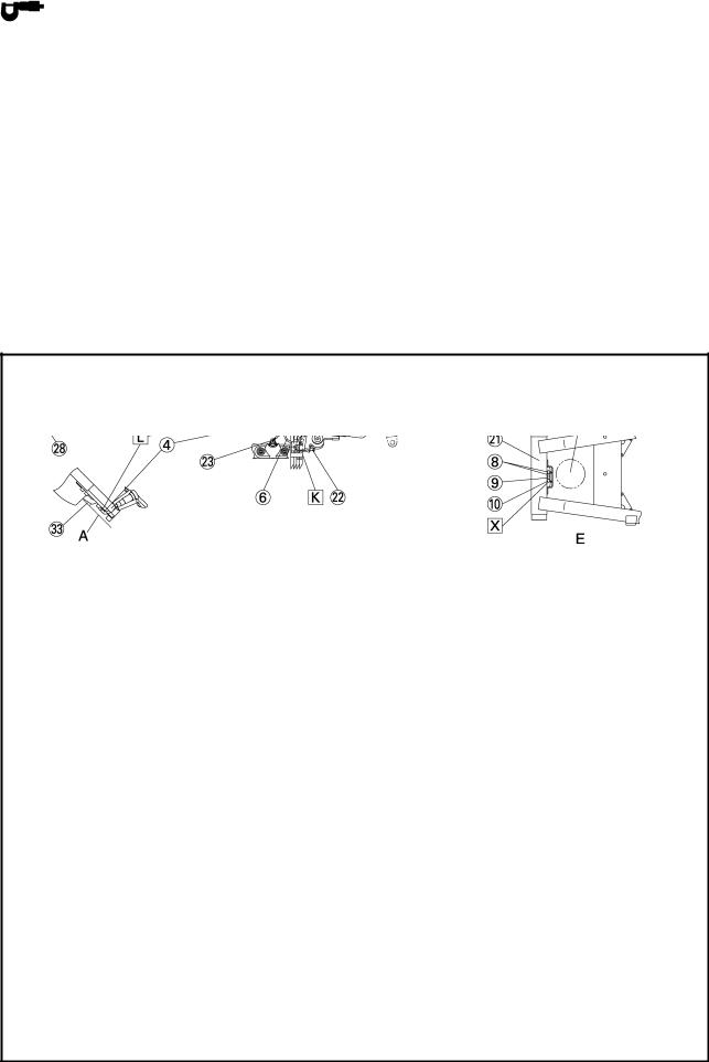
 Route the front wheel sensor lead along the brake hose and clamp it at the position shown the drawing.
 It should be 30 ~ 40 mm (1.18 ~ 1.57 in) from the lower end of the grommet of the brake hose.
 Route the right handlebar switch lead, front brake hose (IN, OUT), front wheel sensor lead and throttle cables through the cover 8.
 Route the right handlebar switch lead, front brake hose (IN) and throttle cables (2 cables) through the wire guide of the upper bracket.
 Fasten the right handlebar switch lead to the handlebar with a band.
 Fasten the main switch lead and immobilizer lead with a clamp so that it faces the front side of the vehicle.
 Fasten the horn lead to the front fork (left side) with a clamp as shown in the drawing. Cut the clamp tip leaving 3 ~ 8 mm (0.12 ~ 0.31 in).
9

CABLE ROUTING |
|
SPEC |
|
|
|
|
|
|
|
|
|
 Fasten the horn lead to the upper side of the under bracket as shown in the drawing. Cut the clamp tip leaving 3 ~ 8 mm (0.12 ~ 0.31 in).
 10 mm (0.39 in)
 Fasten the turn signal light lead (right) together with the coupler to the stay 1.
 Clamp the white tape of headlight sub-wire harness to the stay 1. (For detail of the clamp, refer to section BB.)
 Fasten the wire harness and turn signal light lead (left) together with the coupler to the stay 1.
And locate the turn signal light lead, under the wire harness.
 Route the wire harness through the outside of the bolt.
 To the headlight relay.
 To the ECU.
 After the clamping, direct the band point to the front.
 Clamp the headlight sub-wire harness to the stay 1 with a band.
 Clamp the headlight sub-wire harness to the dent in the stay 1.
 Route the all leads through inside of the headlight adjusting knob. Because of the protruding of the wire harness, it does not have to become the disturbance of operation of the headlight adjusting knob.
 Clamp the meter lead, indicator light lead, headlight sub-wire harness to the stay 1 with a band.
10

CABLE ROUTING |
|
SPEC |
|
|
|
|
|
|
|
|
|
 Fasten the headlight sub-wire harness with the clamp that is passed through the center hole of stay 1.
11

CABLE ROUTING |
|
SPEC |
|
|
|
|
|
|
|
|
|
Stay 3 |
Immobilizer coupler |
Turn signal light relay |
Ignition coil assembly |
Joint coupler |
Headlight relay |
Neutral switch lead |
Tail/brake light lead |
Main relay |
O2 sensor lead |
Rear turn signal light |
Front wheel sensor |
Speed sensor lead |
Rear turn signal light lead |
ECU |
Sidestand switch lead |
Rectifier/regulator lead |
ECU lead |
Pickup coil lead |
Coolant reservoir tank |
Stay 1 |
Fuel tank drain hose |
Rear shock absorber |
6 poles water proof coupler |
Air filter drain hose |
Swingarm |
Boss |
Coolant reservoir tank drain |
Sidestand switch |
Starter motor lead |
hose |
O2 sensor |
Frame |
Battery negative lead |
Cylinder identification sensor |
Engine |
Seat lock cable |
lead |
Oil pipe |
|
|
|
|
|
|
12
CABLE ROUTING |
|
SPEC |
|
|
|
|
|
|
|
|
|
 To the headlight.
 Route the 6 poles water proof coupler through inside of the ECU lead, and the 12 poles coupler through outside of the ECU lead.
 Connect the headlight sub-wire harness coupler in front of ECU and make it not to route above the ECU lead.
 Fasten the wire harness to the stay 1 with a clamp. Clamp position shall be at the position shown in the drawing 1. The knot should be faced to the outside of the vehicle.
 Insert the terminal (black) of the ignition coil lead as shown in the drawing.
 Pass the cylinder identification sensor lead above the left radiator hose.
 Pass the rectifier/regulator lead above the frame cross tube.
 Route the tail/brake light lead through the guides (3 places) of the tail/brake lgiht bracket.
 Fasten the tail/brake light lead at outside of the frame with a clamp. After connecting the tail/brake light lead coupler, insert the surplus wiring between frame, and positioning without routing above the frame.
 Fasten the rectifier/regulator lead with the clamp installed with the rear fender. The clamp tip should face the inner side of the vehicle.
13
CABLE ROUTING |
|
SPEC |
|
|
|
|
|
|
|
|
|
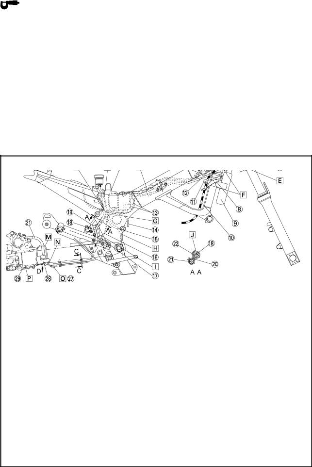
 Route the fuel drain hoses (2 hoses), air filter drain hose, and coolant reservoir tank drain hose trough the clamp. For the fuel drain hose, the white paint mark should be under the clamp. The position is regardless of ranks. Arrange the end of coolant reservoir tank drain hose, air filter case drain hose and fuel drain hose from the clamp.
 The O2 sensor lead should not stick out from the boss seat face to the outside of the vehicle.
  Fasten the neutral switch lead, O2 sensor lead, speed sensor lead, sidestand switch lead and rectifier/regulator lead with the clamp as shown in the drawing. Cut the clamp tip leaving 3 ~ 8 mm (0.12 ~ 0.31 in) and make if face to the outside of the vehicle.
 Less than 20 mm (0.79 in)
 Route the spark plug lead for the right cylinder below the water pipe and behind the hose for the air cut-off valve.
 Route the front wheel sensor lead inside the vehicle and secure it to the front brake hose with a clamp.
 Pass the front wheel sensor lead through the cable holder tightened together with the front brake caliper.
 Fasten the cylinder identification sensor lead to the inner side of the frame with a clamp.
 Pass the front wheel sensor lead between the front brake caliper and front brake hose.
14

CABLE ROUTING |
|
SPEC |
|
|
|
|
|
|
|
|
|
 Pass the harness for the relay between ECU and the main relay.
 Fasten the ECU lead with the clamp installed to the plate of front side hole. Align the positioning tape and the clamp. Install the clamp to the out side of plate.
 Insert the terminal (white) of the spark plug lead as shown in the drawing.
 Pass the fuel drain hose coolant reservoir tankdrain hose and air filter drain hose behind the battery negative lead.
 Route the fuel drain hoses (2 hoses), air filter drain hose and coolant reservoir tank drain hose through the guide located behind the swingarm head pipe. Do not make hoses to cross in the area between D and E.
15

CABLE ROUTING |
|
SPEC |
|
|
|
|
|
|
|
|
|
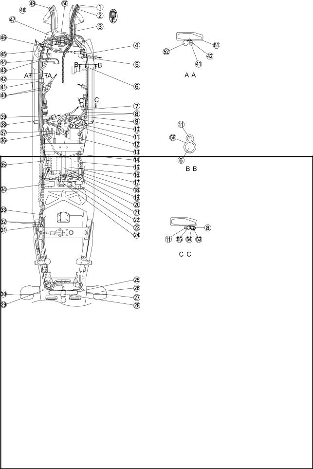
Seat bracket
Front wheel sensor lead ECU (ABS) sub-wire harness ECU (ABS)
Radiator fan motor relay ABS check coupler Brake hose holder
Stay 2
Radiator Clutch cable
Thermo wax hose
Coolant reservoir tank hose Rear brake hose
Starter motor lead Hydraulic unit drain hose
Rear brake light switch lead Rear brake light switch Rear wheel sensor lead Brake fluid reservoir hose Clamp
Rear brake hose (OUT) Rear brake hose (IN) Fuel tank return hose Fuel hose
Fuel tank drain hose Clamp
Clamp
Brake hose holder Rear wheel sensor lead Clamp
16
CABLE ROUTING |
|
SPEC |
|
|
|
|
|
|
|
|
|
 The right and left positions for the starter motor lead and rear wheel sensor lead can be accepted in random oder.
 Pass the brake fluid reservoir hose and the rearbrake light switch lead through the gap between the rear fender and rear frame and route it behind the seat bracket.
 Clamp the coolant reservoir tank hose and brake hose.
Clamping position should be behind the protector and of the coolant reservoir tank hose.
 Route the throttle cables and right handlebar switch lead inside of the brake hose holder.
 Route the clutch cable through the guide of brake hose holder.
 Route the clutch cable through the guide of stay 2.
 Route the rear brake hose and starter motor lead over the frame cross tube.
 Route the hydraulic unit drain hose behind the cross tube, front of the oil hose and also front of the pivot shaft.
 Direct the rear brake light switch lead to the front.
 Clamp the grommet parts of the rear brake hose and rear wheel sensor lead.
 Clamp the ABS check coupler lead. Either upward or downward direction of pawl is acceptable.
 Pass the fuel hose between the fuel tank drain hoses
 Route by the outside of the brake hose.
 Ensure that the leads are not folded.
 Point the tip of the clamp downward and cut the surplus part leaving 0 ~ 5 mm (0 ~ 0.20 in).
17

CABLE ROUTING |
|
SPEC |
|
|
|
|
|
|
|
|
|
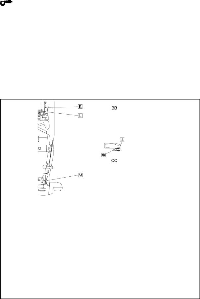
 Route inside the brake hose holder.
 Attach the clamp so that its opening section faces in the direction indicated in the drawing.
 Clamp the grommet which is attached to the sensor lead.
 Make sure to insert it to the deepest point.
 Make sure to catch more than 3 notches. Install the pawl so that it points to the outside of the vehicle.
18

CABLE ROUTING |
|
SPEC |
|
|
|
|
|
|
|
|
|
Throttle cables
Handlebar switch lead (right) Front brake hose
Stay
Front wheel sensor lead Thermo wax hose Intake vacuum hose
Sub-wire harness (air filter case) Oil level switch lead
Hydraulic unit lead
Coolant reservoir tank hose Hydraulic unit assembly Fail-safe relay
Rear brake light switch lead
Battery Rectifier/regulator Rear wheel sensor lead Starter motor lead Battery band
Battery positive lead Lean angle cut-off switch
Atmospheric pressure sensor Fuse (main)
Starter relay
Rear turn signal light lead (right) Rear turn signal light (right) Tail/brake light lead
Tail/brake light
Rear turn signal light lead (left)
19
CABLE ROUTING |
|
SPEC |
|
|
|
|
|
|
|
|
|
Rear turn signal light (left) Joint coupler
Immobilizer coupler Seat lock cable Fuse box
Battery negative lead Hydraulic unit motor coupler
Coolant reservoir tank drain hose Fuel pump lead 2
Fuel pump lead 1
Sub-wire harness (throttle body) Radiator fan motor lead
Cylinder identification sensor lead Hose 1
Bracket 1
Air induction system lead Coolant temperature sensor lead Cover 2
Main switch lead and immobilizer lead Left handlebar switch lead
Boot
Frame
Wire harness
Intake vacuum hose (Joint section) Front brake hose (IN)
Front brake hose (OUT) Clamp
20

CABLE ROUTING |
|
SPEC |
|
|
|
|
|
|
|
|
|
 Put the cover on the coupler for the immobilizer lead and wire harness.
 Install the projection part of the coupler pointing to the connector housing 2.
 Align the projection part of the connector housing 2 with the hole of the locking bracket.
 Attach the boot over the immobilizer coupler.
 To the air induction system.
 To the ECU (ABS).
 To the air filter case.
 Route the sub-wire harness (air filter case) and intake vacuum hose over or side by the brake hose.
 To the oil tank.
 Route the starter motor lead and rear wheel sensor lead under the rear frame attaching boss section.
 Route the starter motor lead and rear wheel sensor lead by the right of the battery. The upper and lower positions of the leads can be accepted in random order.
 Route the battery positive lead under the battery band. (secure with a band)
 Pass the rear turn signal light lead (right) through the right hole of the fender.
 Pass the rear turn signal light leads (right and left) through the clamp installed to the rear fender. Adjust the length of the rear turn signal light lead (left) by folding and then bundle it.
 Pass the rear turn signal light lead (left) through the left hole of the fender.
 Pass the rear turn signal light leads (right and left) between the ribs of the rear fender.
21
CABLE ROUTING |
|
SPEC |
|
|
|
|
|
|
|
|
|
 Pass the seat locking cable through the hole section of the seat bracket of the rear frame. Either direction of the seat locking cable can be accepted.
 Set the immobilizer coupler and joint coupler between the ribs of the rear fender.
 Route the battery negative lead (black lead) above the seat locking cable.
 Route the battery positive lead (red lead) below the seat locking cable.
 Route the battery positive lead together with the rear wheel sensor lead and starter motor lead as shown in the illustration.
 Route the battery negative lead above the battery.
  Route the rear brake light switch lead below the battery band. (secure with a band.)
 Clamp the coolant reservoir tank hose to the hydraulic unit bracket.
 To the fuel pump.
 Fasten the wire harness to the inner side of the frame with the harness wrapping clamp.
 Arrange to route the throttle cable so that its upper side is the return cable and lower side for the pulling cable.
 To the throttle body.
 Route the wire harness, cylinder identification sensor lead and radiator fan motor lead under the bracket 1.
 Route the cylinder identification sensor lead and radiator fan motor lead above the radiator hose.
  To the radiator.
22
 Loading...