


FOREWORD
This Supplementary Service Manual has been prepared to introduce new service and data for the TDM850 '99. For complete service information procedures it is necessary to use this Supplementary Service Manual together with the following manual.
TDM850 '96 SERVICE MANUAL: 4TX-AE1
TDM850 '97 SUPPLEMENTARY SERVICE MANUAL: 4TX-AE2
TDM850 '99
SUPPLEMENTARY
SERVICE MANUAL1998 by Yamaha Motor Co., Ltd.
First Edition, November 1998 All rights reserved.
Any reproduction or unauthorized use without the written permission of Yamaha Motor Co., Ltd. is expressly prohibited.
EB001000
NOTICE
This manual was produced by the Yamaha Motor Company primarily for use by Yamaha dealers and their qualified mechanics. It is not possible to include all the knowledge of a mechanic in one manual, so it is assumed that anyone who uses this book to perform maintenance and repairs on Yamaha motorcycles has a basic understanding of the mechanical ideas and the procedures of motorcycles repair. Repairs attempted by anyone without this knowledge are likely to render the motorcycles unsafe and unfit for use.
Yamaha Motor Company, Ltd. is continually striving to improve all its models. Modifications and significant changes in specifications or procedures will be forwarded to all authorized Yamaha dealers and will appear in future editions of this manual where applicable.
NOTE:
Designs and specifications are subject to change without notice.
IMPORTANT INFORMATION
Particularly important information is distinguished in this manual by the following notations.
CAUTION:
NOTE:
The Safety Alert Symbol means ATTENTION! BECOME ALERT! YOUR SAFETY IS INVOLVED!
Failure to follow WARNING instructions could result in severe injury or death to the motorcycle operator, a bystander or a person inspecting or repairing the motorcycle.
A CAUTION indicates special precautions that must be taken to avoid damage to the motorcycle.
A NOTE provides key information to make procedures easier or clearer.

EB002000
HOW TO USE THIS MANUAL
MANUAL ORGANIZATION
This manual consists of chapters for the main categories of subjects. (See ªIllustrated symbolsº)
1st title 1 : This is the title of the chapter with its symbol in the upper right corner of each page.
2nd title 2 : This title indicates the section of the chapter and only appears on the first page of each section. It is located in the upper left corner of the page.
3rd title 3 : This title indicates a sub-section that is followed by step-by-step procedures accompanied by corresponding illustrations.
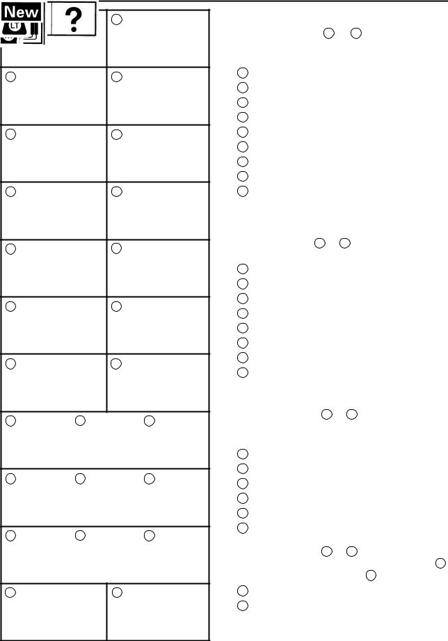
EXPLODED DIAGRAMS
To help identify parts and clarify procedure steps, there are exploded diagrams at the start of each removal and disassembly section.
1.An easy-to-see exploded diagram 4 is provided for removal and disassembly jobs.
2.Numbers 5 are given in the order of the jobs in the exploded diagram. A number that is enclosed by a circle indicates a disassembly step.
3.An explanation of jobs and notes is presented in an easy-to-read way by the use of symbol marks 6 . The meanings of the symbol marks are given on the next page.
4.A job instruction chart 7 accompanies the exploded diagram, providing the order of jobs, names of parts, notes in jobs, etc.
5.For jobs requiring more information, the step-by-step format supplements 8 are given in addition to the exploded diagram and the job instruction chart.
2 |
1 |
4 |
 3
3
6
8
5
7
1 |
2 |
GEN |
SPEC |
|
INFO |
||
|
||
3 |
4 |
|
INSP |
ENG |
|
ADJ |
||
|
||
5 |
6 |
|
COOL |
CARB |
|
7 |
8 |
|
CHAS |
ELEC |
|
9 |
10 |
|
TRBL |
|
|
SHTG |
|
|
11 |
12 |
13 |
14 |
15 |
16 |
17 |
18 |
19 |
20 |
21 |
22 |
23 |
24 |
25 |
EB003000
ILLUSTRATED SYMBOLS
Illustrated symbols 1 to 9 are printed on top right of each page and indicate the subject of each chapter.
1General information
2Specifications
3Periodic inspection and adjustment
4Engine
5Cooling system
6Carburetion
7Chassis
8Electrical
9Troubleshooting
Illustrated symbols 10 to 17 are used to identify the specifications appearing in the text.
10Can be serviced with engine mounted
11Filling fluid
12Lubricant
13Special tool
14Torque
15Wear limit, clearance
16Engine speed
17Ω, V, A
Illustrated symbols 18 to 23 in the exploded diagrams indicate the types of lubricants and lubrication points.
18Apply engine oil
19Apply gear oil
20Apply molybdenum disulfide oil
21Apply wheel bearing grease
22Apply lightweight lithium-soap base grease
23Apply molybdenum disulfide grease
Illustrated symbols 24 to 25 in the exploded diagrams indicate where to apply a locking agent 24 and when to install new parts 25 .
24Apply locking agent (LOCTITE )
25replace

CONTENTS
GENERAL INFORMATION . . . . . . . . . . . . . . . . . . . . . . . . . . . . . . . . . . . . . . . . 1 MOTORCYCLE IDENTIFICATION . . . . . . . . . . . . . . . . . . . . . . . . . . . . . . . 1 VEHICLE IDENTIFICATION NUMBER . . . . . . . . . . . . . . . . . . . . . . . . 1 MODEL LABEL . . . . . . . . . . . . . . . . . . . . . . . . . . . . . . . . . . . . . . . . . . . . 1
SPECIFICATIONS . . . . . . . . . . . . . . . . . . . . . . . . . . . . . . . . . . . . . . . . . . . . . . . . 2 GENERAL SPECIFICATIONS . . . . . . . . . . . . . . . . . . . . . . . . . . . . . . . . . . . 2 MAINTENANCE SPECIFICATIONS . . . . . . . . . . . . . . . . . . . . . . . . . . . . . . 3 ENGINE . . . . . . . . . . . . . . . . . . . . . . . . . . . . . . . . . . . . . . . . . . . . . . . . . . 3 CHASSIS . . . . . . . . . . . . . . . . . . . . . . . . . . . . . . . . . . . . . . . . . . . . . . . . . 3 ELECTRICAL . . . . . . . . . . . . . . . . . . . . . . . . . . . . . . . . . . . . . . . . . . . . . 4 CABLE ROUTING . . . . . . . . . . . . . . . . . . . . . . . . . . . . . . . . . . . . . . . . . . . . . 5
PERIODIC INSPECTION AND ADJUSTMENT . . . . . . . . . . . . . . . . . . . . . . . 13 INTRODUCTION . . . . . . . . . . . . . . . . . . . . . . . . . . . . . . . . . . . . . . . . . . . . . . 13 PERIODIC MAINTENANCE/LUBRICATION INTERVALS . . . . . . . . . . . 13 SEAT, TAIL COVER AND FUEL TANK . . . . . . . . . . . . . . . . . . . . . . . . . . . 15 SEAT, TAIL COVER AND FUEL TANK . . . . . . . . . . . . . . . . . . . . . . . . 15 ENGINE . . . . . . . . . . . . . . . . . . . . . . . . . . . . . . . . . . . . . . . . . . . . . . . . . . . . . . 16 CARBURETOR SYNCHRONIZATION . . . . . . . . . . . . . . . . . . . . . . . . 16 ENGINE OIL LEVEL INSPECTION . . . . . . . . . . . . . . . . . . . . . . . . . . . 18 ENGINE OIL REPLACEMENT . . . . . . . . . . . . . . . . . . . . . . . . . . . . . . . 19 FUEL LINE INSPECTION . . . . . . . . . . . . . . . . . . . . . . . . . . . . . . . . . . . 21 CLUTCH . . . . . . . . . . . . . . . . . . . . . . . . . . . . . . . . . . . . . . . . . . . . . . . . . . . . . 22 CLUTCH . . . . . . . . . . . . . . . . . . . . . . . . . . . . . . . . . . . . . . . . . . . . . . . . . . 22 INSTALLATION . . . . . . . . . . . . . . . . . . . . . . . . . . . . . . . . . . . . . . . . . . . . 23
INSTRUMENT FUNCTIONS . . . . . . . . . . . . . . . . . . . . . . . . . . . . . . . . . . . . |
24 |
COMBINATION METER . . . . . . . . . . . . . . . . . . . . . . . . . . . . . . . . . . . . |
24 |
SIGNAL SYSTEM . . . . . . . . . . . . . . . . . . . . . . . . . . . . . . . . . . . . . . . . . . . . . 25 CIRCUIT DIAGRAM . . . . . . . . . . . . . . . . . . . . . . . . . . . . . . . . . . . . . . . . 25 TROUBLESHOOTING . . . . . . . . . . . . . . . . . . . . . . . . . . . . . . . . . . . . . . 27 SIGNAL SYSTEM CHECK . . . . . . . . . . . . . . . . . . . . . . . . . . . . . . . . . . 28
FUEL PUMP SYSTEM . . . . . . . . . . . . . . . . . . . . . . . . . . . . . . . . . . . . . . . . . 32 CIRCUIT DIAGRAM . . . . . . . . . . . . . . . . . . . . . . . . . . . . . . . . . . . . . . . . 32 FUEL PUMP CIRCUIT OPERATION . . . . . . . . . . . . . . . . . . . . . . . . . . 33 TROUBLESHOOTING . . . . . . . . . . . . . . . . . . . . . . . . . . . . . . . . . . . . . . 34 CHECKING THE FUEL PUMP . . . . . . . . . . . . . . . . . . . . . . . . . . . . . . . 36
TDM850 '99WIRING DIAGRAM
GEN
MOTORCYCLE IDENTIFICATION INFO
EB100000
GENERAL INFORMATION
MOTORCYCLE IDENTIFICATION
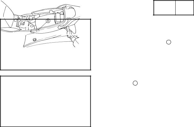
VEHICLE IDENTIFICATION NUMBER
The vehicle identification number 1 is stamped into the right side of the steering head.
MODEL LABEL
The model label 1 is affixed to the frame. This information will be needed to order spare parts.
±1±

GENERAL SPECIFICATIONS SPEC 
SPECIFICATIONS
GENERAL SPECIFICATIONS
Item |
|
Standard |
|
|
|
Model: |
|
TDM850 |
|
|
|
Model code: |
|
4TX4 |
|
|
|
Basic weight (With oil and full fuel tank): |
232 kg |
|
|
|
|
Carburetor: |
|
|
Type/quantity |
|
BDSR38/2 |
Manufacturer |
|
MIKUNI |
|
|
|
Transmission |
|
|
Primary reduction system |
|
Spur gear |
Primary reduction ratio |
|
67/39 (1.718) |
Secondary reduction system |
|
Chain drive |
Secondary reduction ratio |
|
43/16 (2.688) |
Transmission type |
|
Constant mesh 5-speed |
Operation |
|
Left foot operation |
Gear ratio |
1st |
37/14 (2.643) |
|
2nd |
37/19 (1.947) |
|
3rd |
30/20 (1.500) |
|
4th |
27/23 (1.174) |
|
5th |
27/28 (0.964) |
|
|
|
Bulb wattage quantity |
|
|
Meter light |
|
12V 2 W 3 |
Indicator lights |
|
|
Neutral |
|
14 V 1.4 W 1 |
Turn |
|
14 V 1.4 W 2 |
High beam |
|
14 V 1.4 W 1 |
Fuel |
|
12 V 2 W 1 |
Water tempere |
|
14 V 1.4 W 1 |
±2±

|
MAINTENANCE SPECIFICATIONS |
|
SPEC |
|
|||||||
MAINTENANCE SPECIFICATIONS |
|
|
|
|
|
|
|
|
|||
|
|
|
|
|
|
|
|
||||
ENGINE |
|
|
|
|
|
|
|
|
|
|
|
|
|
|
|
|
|
|
|
|
|
||
Item |
|
Standard |
|
|
|
|
|
Limit |
|||
|
|
|
|
|
|
|
|
|
|
|
|
Clutch: |
|
|
|
|
|
|
|
|
|
|
|
Clutch spring free length |
|
50 mm |
|
|
|
|
|
|
48 mm |
||
Quantity |
|
6 |
|
|
|
|
|
|
|
|
|
|
|
|
|
|
|
|
|
|
|
|
|
Carburetor: |
|
|
|
|
|
|
|
|
|
|
|
I.D. mark |
|
4TX4 40 |
|
|
|
|
|
|
|
|
|
Main jet |
|
#147.5 |
|
|
|
|
|
|
|
|
|
Main air jet |
|
#65 |
|
|
|
|
|
|
|
|
|
Jet needle |
|
#1: 6DJP17 #2: 6CL1 |
|
|
|
|
|
|
|
|
|
Needle jet |
|
P-O |
|
|
|
|
|
|
|
|
|
Pilot air jet 1 |
|
#87.5 |
|
|
|
|
|
|
|
|
|
Pilot air jet 2 |
|
#120 |
|
|
|
|
|
|
|
|
|
Pilot outlet |
|
1.0 |
|
|
|
|
|
|
|
|
|
Pilot jet |
|
#17.5 |
|
|
|
|
|
|
|
|
|
Bypass 1 |
|
0.8 |
|
|
|
|
|
|
|
|
|
Bypass 2 |
|
0.9 |
|
|
|
|
|
|
|
|
|
Bypass 3 |
|
0.8 |
|
|
|
|
|
|
|
|
|
Pilot screw |
|
2.0 |
|
|
|
|
|
|
|
|
|
Valve seat size |
|
1.5 |
|
|
|
|
|
|
|
|
|
Starter jet 1 |
|
#32.5 |
|
|
|
|
|
|
|
|
|
Starter jet 2 |
|
0.9 |
|
|
|
|
|
|
|
|
|
Throttle valve size |
|
#95 |
|
|
|
|
|
|
|
|
|
Fuel level |
|
4.4 X 5.4 mm |
|
|
|
|
|
|
|
|
|
Engine idle speed |
|
1050 X 1250 r/min |
|
|
|
|
|
|
|
|
|
Intake vacuum |
|
36.0 X 38.7 kPa (270 X 290 mmHg) |
|
|
|
||||||
|
|
|
|
|
|
|
|
|
|
|
|
Fuel pump: |
|
|
|
|
|
|
|
|
|
|
|
Type |
|
Electrical type |
|
|
|
|
|
|
|
|
|
Model/manufacturer |
|
4TX/MITSUBISHI |
|
|
|
|
|
|
|
|
|
Output pressure |
|
7 kPa (0.07 kgf/cm2, 0.07 bar) |
|
|
|
||||||
CHASSIS |
|
|
|
|
|
|
|
|
|
|
|
|
|
|
|
|
|
|
|
|
|||
|
|
|
|
Tightening |
|
|
|
||||
Item |
|
Thread size |
|
|
torque |
|
Remarks |
||||
|
|
|
|
Nm |
|
m kgf |
|
|
|
||
Fuel sender and fuel tank |
|
M5 |
|
3.8 |
|
0.38 |
|
|
|
||
Fuel pump and bracket |
|
M6 |
|
6.5 |
|
0.65 |
|
|
|
||
Bracket and frame |
|
M6 |
|
6.5 |
|
0.65 |
|
|
|
||
|
|
|
|
|
|
|
|
|
|
|
|
±3±
|
MAINTENANCE SPECIFICATIONS |
|
SPEC |
|
|||
ELECTRICAL |
|
|
|
|
|
|
|
|
|
|
|
|
|
|
|
|
|
|
|
|
|
|
|
Item |
|
|
Standard |
|
|
Limit |
|
|
|
|
|
|
|
|
|
Charging system: |
|
|
|
|
|
|
|
Type |
|
A.C. magneto |
|
|
|
||
Model/manufacturer |
|
TLN252/DENSO |
|
|
|
||
Nominal output |
|
14 |
V 25 A at 5,000 r/min |
|
|
|
|
Stator coil resistance |
|
0.23 X 0.35 Ω at 20_C/W-W |
|
|
|
||
Starter relay: |
|
|
|
|
|
|
|
Model/manufacturer |
|
MS5F-421/JIDECO |
|
|
|
||
Amperage rating |
|
180 A |
|
|
|
||
Coil winding resistance |
|
4.2 X 4.6 Ω at 20_C |
|
|
|
||
Fuel sender: |
|
|
|
|
|
|
|
Model/manufacturer |
|
4TX/NIPPON/SEIKI |
|
|
|
||
resistance |
full |
4 X 10Ω |
|
|
|
||
|
empty |
90 |
X 100Ω |
|
|
|
|
|
|
|
|
|
|
|
|
Fuel pump relay: |
|
|
|
|
|
|
|
Model/manufacturer |
|
G8R-30Y-B/OMRON |
|
|
|
||
Coil winding resistance |
|
225 Ω ± 10% |
|
|
|
||
|
|
|
|
|
|
|
|
Hazard relay: |
|
|
|
|
|
|
|
Model/manufacturer |
|
4KM-00/MATSUSHITA |
|
|
|
||
Coil winding resistance |
|
72 |
X 88 Ω at 20_C |
|
|
|
|
Circuit breakers: |
|
|
|
|
|
|
|
Type |
|
Fuse |
|
|
|
||
Amperage for individual circuits |
|
|
|
|
|
|
|
Main fuse |
|
30 |
A 1 |
|
|
|
|
Headlight fuse |
|
15 |
A 1 |
|
|
|
|
Signal system fuse |
|
15 |
A 1 |
|
|
|
|
Ignition fuse |
|
10 |
A 1 |
|
|
|
|
Fuse (position light and hazard) |
10 |
A 1 |
|
|
|
||
Radiator fan fuse |
|
7.5 A 1 |
|
|
|
||
Back up |
|
5 A 1 |
|
|
|
||
Reserve fuse |
|
15 |
A 1 |
|
|
|
|
Reserve fuse |
|
10 |
A 1 |
|
|
|
|
Reserve fuse |
|
5 A 1 |
|
|
|
||
|
|
|
|
|
|
|
|
±4±
|
|
|
CABLE ROUTING |
|
SPEC |
|
||
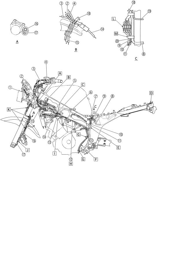
CABLE ROUTING |
|
|
|
|
|
|
|
|
|
|
|
|
|
|
|
||
1 |
Throttle cable 1 |
16 |
Ignition coil (left) lead |
G |
Align the brake hose white mark to |
|||
2 |
Right handlebar switch lead |
17 |
Ignition coil (right) lead |
|
the mark of bracket. |
|||
3 |
Brake hose |
18 |
Negative lead |
H |
Fasten the brake hose with a plas- |
|||
4 |
Clutch cable |
|
|
|
tic band and cut the end of band. |
|||
5 |
Main switch lead |
A |
Fasten the right handlebar switch |
I |
Pass the speed sensor lead be- |
|||
6 |
Left handlebar switch lead |
|
lead with a plastic band. |
|
tween throttle cable and clutch |
|||
7 |
Horn lead |
B |
Fasten the handlebar switch lead |
|
cable and fasten to the frame head |
|||
8 |
Starter cable |
|
with a plastic band. |
|
pipe. |
|
|
|
9 |
Speed sensor lead |
C |
50 mm |
J |
Pass the wireharness and hoses |
|||
10 |
Coolant reservoir hose |
D |
Fasten the horn lead with a plastic |
|
under the frame. |
|||
11 |
Headlight lead |
|
band. |
K |
Fasten the coolant reservoir hose |
|||
12 |
Meter light lead |
E |
60 mm |
|
with a plastic band. |
|||
13 |
Thermo unit lead |
F |
Set the clamp within 10 mm from |
|
|
|
|
|
14 |
Thermo switch lead |
|
the upper end of protector. |
|
|
|
|
|
15 |
Fan motor lead |
|
|
|
|
|
|
|
|
|
|
|
|
|
|
|
|
|
|
|
|
|
|
|
|
|
±5±

LFasten the meter lead and headlight lead with a plastic band.
M Fasten the wireharness with a plastic band.
NFasten the wireharness, right handlebar switch lead meter lead and headlight lead with a plastic band.
OConnect the coupler and insert to the protector.
CABLE ROUTING SPEC 
PFasten the wireharness with a plastic band.
QFasten the wireharness and ignition coil (left) lead with a plastic band.
RFasten the wireharness right handlebar switch lead, main switch lead fan motor lead with a plastic band.
SSet the ignition coil at the mark upward.
TProtector is under the coupler.
±6±
|
|
|
CABLE ROUTING |
|
SPEC |
|
|
|
|
|
|
|
|
|
|
1 |
Front flasher light (left) lead |
11 A.C. magneto lead |
A Fasten the left handlebar switch |
||||
2 |
Main switch lead |
12 |
Air filter case breather hose |
lead and main switch lead with a |
|||
3 |
Starter cable 1 |
13 |
Carburetor heater hose |
plastic band. |
|||
4 |
Left handlebar switch lead |
14 |
Starter cable 2 |
B Route the wireharness to the rear- |
|||
5 |
Spark plug lead |
15 |
Thermo switch lead |
side of the frame pipe. |
|||
6 |
Carburetor breather hose |
16 |
Brake hose |
C Route the starter cable through ra- |
|||
7 |
Fuel hose |
17 |
Speed sensor lead |
diator hose upward and spark plug |
|||
8 |
Coolant reservoir hose |
18 |
Wire harness |
lead rear side and in front of air fil- |
|||
9 |
Sidestand switch lead |
19 |
Flasher relay lead |
ter case breather hose. Route the |
|||
10 |
Neutral switch lead |
20 |
Fuel pump lead |
spark plug lead to the outside of |
|||
|
|
|
|
the carburetor starter bracket and |
|||
|
|
|
|
carburetor heater hose. |
|||
|
|
|
|
|
|
|
|
|
|
|
|
|
|
|
|
±7±
 Loading...