


WaveRunner
FX160
FX160 Cruiser
SERVICE MANUAL MANUEL D’ATELIER WARTUNGSHANDBUCH MANUAL DE SERVICIO
E
F
D
ES
460094 |
F1S-28197-ZG-C1 |

E 
NOTICE
This manual has been prepared by Yamaha primarily for use by Yamaha dealers and their trained mechanics when performing maintenance procedures and repairs to Yamaha equipment. It has been written to suit the needs of persons who have a basic understanding of the mechanical and electrical concepts and procedures inherent in the work, for without such knowledge attempted repairs or service to the equipment could render it unsafe or unfit for use.
Because Yamaha has a policy of continuously improving its products, models may differ in detail from the descriptions and illustrations given in this publication. Use only the latest edition of this manual. Authorized Yamaha dealers are notified periodically of modifications and significant changes in specifications and procedures, and these are incorporated in successive editions of this manual.
A10001-0*
WaveRunner
FX160, FX160 Cruiser
SERVICE MANUAL ©2004 by Yamaha Motor Co., Ltd.
1st Edition, February 2004 All rights reserved.
Any reprinting or unauthorized use without the written permission of Yamaha Motor Co., Ltd.
is expressly prohibited. Printed in Japan

|
F |
D |
ES |
|
|
|
|
AVIS |
ANMERKUNG |
ADVERTENCIA |
Ce manuel a été préparé par Yamaha principalement à l’intention des concessionnaires Yamaha et de leurs mécaniciens qualifiés afin de les assister lors de l’entretien et la réparation des produits Yamaha. Ce manuel est destiné à des personnes possédant les connaissances de base en mécanique et en électricité sans lesquelles l’exécution de réparations ou d’entretiens peut rendre les machines impropres ou dangereuses à l’emploi.
Yamaha s’efforce en permanence d’améliorer ses produits. Par conséquent, il se peut que les modèles diffèrent légèrement des descriptions et illustrations de ce manuel. Les modifications et les changements significatifs dans les caractéristiques ou les procédés sont notifiés à tous les concessionnaires Yamaha et sont publiés dans les éditions ultérieures de ce manuel.
A10001-0*
WaveRunner
FX160, FX160 Cruiser
MANUEL D’ENTRETIEN ©2004 Yamaha Motor Co., Ltd. 1ère Edition, février 2004 Tous droits réservés.
Toute réimpression ou utilisation sans la permission écrite de la Yamaha Motor Co., Ltd.
est formellement interdite. Imprimé au Japon
Dieses Handbuch wurde von Yamaha vorrangig für Yahama-Ver- tragshändler und deren qualifizierte Mechaniker geschrieben, um sie bei der Durchführung von Wartungsund Reparaturarbeiten an Yamaha-Moto- ren zu unterstützen. Es werden Grundkenntnisse der mechanischen und elektrischen Wirkungsweise und der Arbeitsverfahren vorausgesetzt, denn ohne diese Grundkenntnisse versuchte Wartungsund Reparaturarbeiten machen das Produkt eher unsicher oder sogar gebrauchsunfähig.
Yamaha ist stets bestrebt, ihre Produkte ständig zu verbessern. Einzelne Modelle können im Detail von den hier enthaltenen Beschreibungen und Abbildungen abweichen. Benutzen Sie immer nur die neueste Ausgabe dieses Handbuchs. Autorisierte Yamaha-Vertragshändler werden regelmäßig vorab über Modifikationen und wesentliche Änderungen der technischen Daten und Verfahren unterrichtet, die in der jeweils nächsten Ausgaben dieses Handbuchs eingearbeitet werden.
A10001-0*
WaveRunner
FX160, FX160 Cruiser
WARTUNGSHANDBUCH ©2004 Yamaha Motor Co., Ltd. 1. Ausgabe, Februar 2004 Sämtliche Rechte vorbehalten. Die drucktechnische Wiedergabe und unberechtigte Verwendung ist ohne ausdrückliche schriftliche Genehmigung seitens der Yamaha Motor Co., Ltd
nicht gestattet. Gedruckt in Japan
Este manual ha sido preparado por Yamaha principalmente para que lo empleen los concesionarios Yamaha y sus mecánicos cualificados al llevar a cabo los procedimientos de mantenimiento y de reparación de los equipos Yamaha. Se ha escrito para adaptarlo a las necesidades de las personas que ya tienen un conocimiento básicos de los conceptos mecánicos y eléctricos y de los procedimientos inherentes al trabajo, porque sin tales conocimientos las reparaciones o el servicio del equipo podría dejar el equipo inseguro o inadecuado para la utilización.
Puesto que Yamaha sigue una política de mejora continua de sus productos, los modelos pueden diferir en detalles de las descripciones e ilustraciones dadas en esta publicación. Emplee sólo la última edición de este manual. Se notifica periódicamente a los concesionarios autorizados Yamaha sobre las modificaciones y cambios importantes en las especificaciones y procedimientos, y tales cambios se incorporan en las ediciones subsiguientes de este manual.
A10001-0*
WaveRunner
FX160, FX160 Cruiser
MANUAL DE SERVICIO ©2004, Yamaha Motor Co., Ltd. 1ª edición, febrero 2004 Reservados todos los derechos. Se prohíbe expresamente toda reimpresión o utilización no autorizada de este manual sin el consentimiento por escrito de Yamaha Motor Co., Ltd. Impreso en Japón

E 
HOW TO USE THIS MANUAL
MANUAL FORMAT
All of the procedures in this manual are organized in a sequential, step-by-step format. The information has been compiled to provide the mechanic with an easy to read, handy reference that contains comprehensive explanations of all disassembly, repair, assembly, and inspection operations.
In this revised format, the condition of a faulty component will precede an arrow symbol and the course of action required will follow the symbol, e.g.,
• Bearings
Pitting/scratches → Replace.
To assist you in finding your way through this manual, the section title and major heading is given at the top of every page.
ILLUSTRATIONS
The illustrations within this service manual represent all of the designated models.
CROSS REFERENCES
The cross references have been kept to a minimum. Cross references will direct you to the appropriate section or chapter.

|
F |
D |
ES |
|
|
|
|
UTILISATION DU
MANUEL
FORMAT DU MANUEL
Toutes les procédures décrites dans ce manuel sont organisées de manière séquentielle, pas à pas. Les informations ont été rassemblées afin de fournir au mécanicien une référence simple à lire et pratique qui comporte néanmoins toutes les explications nécessaires au démontage, à la réparation, au montage et à l’inspection.
Dans cette forme revue, l’état d’un composant défectueux précédera une flèche symbolisée et la procédure à mettre e oeuvre suivra le symbole, par ex,
•Roulements Corrosion/endommagement →
Remplacer.
Pour vous orienter dans ce manuel, le Titre de section et le Principal intitulé sont indiqués sur chaque page.
ILLUSTRATIONS
Les illustrations dans ce manuel d’entretien représentent tous les modèles désignés.
REFERENCES
Elles ont été réduites au minimum. Elles vous renvoient à la partie ou au chapitre approprié.
ZUR VERWENDUNG DIESES HANDBUCHS
AUFBAU
Alle Verfahren in diesem Handbuch sind in logischer Reihenfolge Schritt für Schritt erklärt. Es sollte auf diese Weise ein leicht zu lesendes, bequem zu handhabendes Referenzmaterial geboten werden, in dem alle Demontagen, Reparaturen, Zusammenbauund Inspektionsarbeiten ausführlich beschrieben sind. In dieser abgeänderten Form erscheint nach dem möglicherweise fehlerhaften Zustand eines Teils ein Pfeil und die erforderliche Gegenmaßnahme. Bsp:
•Lager Lochfraß/Beschädigung →
Ersetzen.
Um das Auffinden von gewünschten Stellen im Handbuch zu erleichtern, steht oben auf jeder Seite der Titel des Kapitels und des Abschnitts.
ILLUSTRATIONEN
Die Illustrationen in diesem Wartungshandbuch beziehen sich auf alle bezeichneten Modelle.
QUERVERWEISE
Querverweise sind auf ein Minimum beschränkt worden und verweisen auf die betreffenden Abschnitte oder Kapitel.
COMO UTILIZAR ESTE
MANUAL
FORMATO DEL MANUAL
Todos los procedimientos de este manual se han preparado de forma secuencial, paso a paso. La información ha sido compilada con el fin de ofrecer al mecánico una referencia útil y de fácil lectura que contiene amplias explicaciones de todas las operaciones de desmontaje, reparación, montaje e inspección.
En este formato revisado, la condición de un componente averiado irá precedida de un símbolo de flecha y el curso de la acción requerida seguirá al símbolo, por ejemplo:
•Cojinetes
Picado/daños → Reemplazar.
Para ayudarle a orientarse a través de este manual, en la parte superior de cada página figuran el título de la sección y el encabezamiento principal.
ILUSTRACIONES
Las ilustraciones de este manual de servicio corresponden a todos los modelos mencionados.
REFERENCIAS
Las referencias se han reducido al mínimo. Éstas le remitirán directamente a la sección o al capítulo correspondiente.
E 
IMPORTANT INFORMATION
In this Service Manual particularly important information is distinguished in the following ways.
The Safety Alert Symbol means ATTENTION! BECOME ALERT! YOUR SAFETY IS INVOLVED!

 WARNING
Failure to follow WARNING instructions could result in severe injury or death to the machine operator, passenger(s), a bystander, or a person inspecting or repairing the watercraft.
CAUTION:
A CAUTION indicates special precautions that must be taken to avoid damage to the watercraft.
NOTE:
A NOTE provides key information to make procedures easier or clearer.
IMPORTANT:
This part has been subjected to change of specification during production.

|
F |
D |
ES |
|
|
|
|
INFORMATIONS IMPORTANTES
Les informations particulièrement importantes contenues dans ce manuel d’entretien sont signalées de diverses manières.
 Le symbole d’alerte sécurité signifie ATTENTION! SOYEZ ATTENTIF! VOTRE SECURITE EST MENACEE!
 AVERTISSEMENT
Le non-respect d’une instruction AVERTISSEMENT peut entraîner de graves blessures, voire même la mort, pour le pilote, le(s) passager(s), un spectateur ou la personne inspectant ou réparant le scooter.
ATTENTION:
ATTENTION indique les consignes qui doivent être respectées afin d’éviter d’endommager le scooter nautique.
N.B.:
N.B. donne des informations importantes qui facilitent et expliquent les différentes opérations.
IMPORTANT: 
Les spécifications de cette partie ont subi des modifications au cours de la production.
WICHTIGE INFORMATIONEN
In diesem Wartungshandbuch sind besonders wichtige Informationen auf folgende Weise hervorgehoben.
 Dieses Warnsymbol bedeutet: VORSICHT! ES GEHT UM IHRE SICHERHEIT!
 WARNUNG
Ein Versäumnis die WARNUNGHinweise zu befolgen könnte ernsthafte Verletzungen oder den Tod für den Fahrer, den oder die Beifahrer oder für eine sich in der Nähe befindlichen Person, oder für eine Person, die das Wasserfahrzeug inspiziert oder repariert, zur Folge haben.
ACHTUNG:
Die Kennzeichnung ACHTUNG bezeichnet spezielle Verfahren, die befolgt werden müssen, um eine Beschädigung des Wasserfahrzeugs zu vermeiden.
HINWEIS:
Ein HINWEIS enthält Informationen, die einen Vorgang einfacher oder deutlicher machen.
WICHTIG: 
Dieser Teil ist während der Produktion verändert worden.
DATOS IMPORTANTES
Este Manual de servicio contiene datos importantes indicados de la siguiente manera:
 El símbolo de alerta de seguridad significa ¡ATENCION, ESTA EN JUEGO SU PROPIA SEGURIDAD!
 ATENCION
La inobservancia de las instrucciones de ADVERTENCIA pueden provocar lesiones graves o un accidente mortal al usuario de la máquina, el o los pasajeros, a una persona que se encuentre en las inmediaciones o a la persona que esté revisando o reparando la moto de agua.
PRECAUCION:
Este tipo de instrucción indica precauciones especiales que debe observar para evitar dañar la moto de agua.
NOTA:
La NOTA proporciona información clave que facilita o clarifica determinados procedimientos.
IMPORTANTE:
Esta pieza ha sido sometida a cambios de especificación durante el proceso de fabricación.

E 
HOW TO USE THIS MANUAL
1To help identify parts and clarify procedure steps, there are exploded diagrams at the start of each removal and disassembly section.
2Numbers are given in the order of the jobs in the exploded diagram.
3Symbols indicate parts to be lubricated or replaced (see “SYMBOLS”).
4A job instruction chart accompanies the exploded diagram, providing the order of jobs, names of parts, notes in jobs, etc.
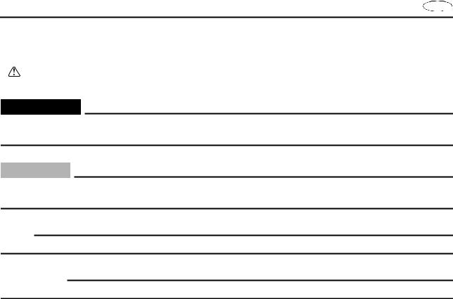
5Dimension figures and the number of parts, are provided for fasteners that require a tightening torque.
Example: |
|
Bolt or screw size |
10 × 25 mm : M10 (D) × 25 mm (L) |
D
L
6 Jobs requiring more information (such as special tools and technical data) are described sequentially.
|
F |
D |
ES |
|
|
|
|
UTILISATION DU MANUEL
1Pour vous aider à identifier les différentes pièces et à comprendre les diverses étapes opératoires, vous trouverez des vues éclatées au début de chaque partie de dépose et de démontage.
2Les chiffres sont indiqués dans l’ordre des opérations à effectuer sur le schéma en vue éclatée.
3Les symboles indiquent les pièces à lubrifier et à remplacer (voir “SYMBOLES”).
4Un tableau d’instructions suit la vue éclatée et indique l’ordre des opérations, le nom des pièces, des conseils pratiques, etc.
5Les dimensions et le numéro des pièces sont fournis pour les éléments de fixation qui nécessitent un couple de serrage.
Exemple:
Taille de boulon ou de vis 10 × 25 mm :
M10 (D) × 25 mm (L)
D
L
6Les opérations nécessitant davantage d’explications (indications par exemple d’un outillage spécial ou de données techniques) sont décrites de manière séquentielle.
VERWENDUNG DIESES HANDBUCHES
1 Um Teile leichter identifizieren und Verfahrensschritte klarstellen zu können, gibt es am Beginn eines jeden Ausbauund Demontageabschnitts Explosionszeichnungen.
2 Die Nummern entsprechen der Reihenfolge der Arbeitsschritte in der Explosionszeichnung.
3Symbole weisen auf Teile hin, die geschmiert oder ersetzt werden müssen. (siehe “SYMBOLE”).
4Zur Explosionszeichnung gibt es eine Arbeitsschritt-Tabelle in der die Reihenfolge der Arbeitsschritte, Bezeichnung der Teile und Hinweise zu den Arbeitsschritten usw. aufgeführt werden.
5Größenbezeichnungen und Teilenummern werden für Verbindungselemente aufgeführt, die ein Anzugsdrehmoment benötigen.
Beispiel:
Schraubengröße 10 × 25 mm :
M10 (D) × 25 mm (L)
D
L
6Arbeitsschritte, die mehr Informationen benötigen (wie z. B. Spezialwerkzeuge und technische Daten), werden der Reihe nach beschrieben.
COMO UTILIZAR ESTE MANUAL
1Este manual incluye diagramas detallados al comienzo de cada sección de extracción y desmontaje para ayudarle a identificar las piezas y clarificar los pasos de los procedimientos.
2Los números corresponden al orden de las tareas del diagrama detallado.
3Los símbolos indican las piezas que deben ser engrasadas o reemplazadas (consultar “SIMBOLOS”).
4La tabla de las instrucciones de las tareas se adjunta con el diagrama detallado incluyendo el orden de la tarea, los nombres de las piezas, las notas para las tareas, etc.
5Se proporcionan las cifras de las dimensiones y el número de las piezas para las fijaciones que requieran una torsión de apriete.
Por ejemplo:
Tamaño del perno o del tornillo 10 × 25 mm :
M10 (D) × 25 mm (L)
D
L
6 Las tareas que requieran mayor información (tales como herramientas especiales y datos técnicos) se describen por orden de secuencia.
E 
1 |
2 |
|
|||
|
|
|
|
|
|
|
GEN |
|
|
SPEC |
|
|
INFO |
|
|
|
|
|
|
|
|
|
|
3 4
INSP  FUEL
FUEL
ADJ
5 |
6 |
POWR |
JET |
|
PUMP |
||
|
||
7 |
8 |
|
ELEC – + |
HULL |
|
|
HOOD |
|
9 |
0 |
|
TRBL |
|
|
ANLS |
|
|
A |
B |
C D
T .
R .
E F
E |
G H
A |
M |
I J
GM |
4 |
K L
LT |
LT |
271 |
242 |
M N
LT
SS
572
A50001-1-4
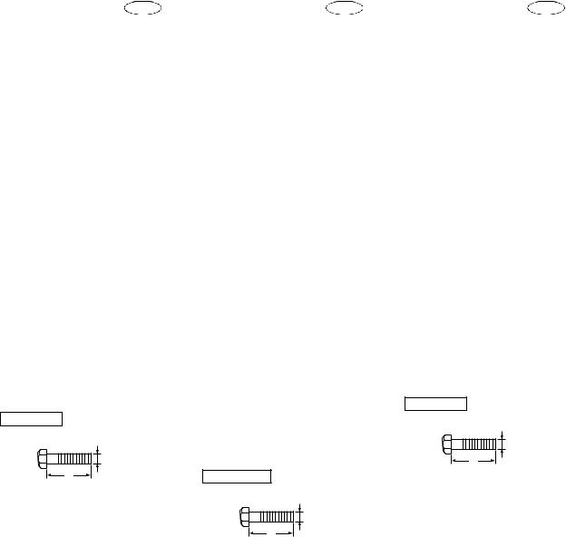
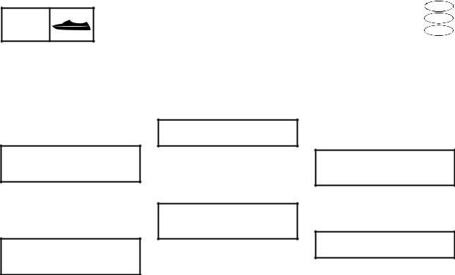
SYMBOLS
Symbols 1 to 9 are designed to indicate the content of a chapter.
1General Information
2Specifications
3Periodic Inspection and Adjustment
4Fuel System
5Power Unit
6Jet Pump Unit
7Electrical System
8Hull and Hood
9Trouble Analysis
Symbols 0 to E indicate specific data.
0 Special tool
ASpecified oil or fluid
BSpecified engine speed
CSpecified tightening torque
DSpecified measurement
ESpecified electrical value (resistance, voltage, electric current)
Symbols F to H in an exploded diagram indicate the grade of lubricant and the lubrication point.
FApply Yamaha 4-stroke motor oil
GApply water resistant grease
(Yamaha grease A, Yamaha marine grease)
HApply molybdenum disulfide grease
Symbols I to N in an exploded diagram indicate the type of sealant or locking agent and the application point.
IApply Gasket Maker
JApply Yamabond No. 4
KApply LOCTITE 271 (red)
LApply LOCTITE 242 (blue)
MApply LOCTITE 572
NApply silicone sealant
NOTE:
Additional symbols may be used in this manual.
|
F |
D |
ES |
|
|
|
|
A50001-1-4
SYMBOLES
Les symboles 1 à 9 servent d’onglets et indiquent le contenu d’un chapitre.
1Informations générales
2Spécifications
3Inspection périodique et réglage
4Système d’alimentation
5Moteur
6Pompe de propulsion
7Equipement électrique
8Coque et capot
9Dépannage
Les symboles 0 à E apportent certaines précisions:
0 Outil d’entretien spécial
AHuile ou liquide spécifié
BVitesse du moteur spécifiée
CCouple de serrage spécifié
DMesure spécifiée
EValeur électrique spécifiée (résistance, tension, courant électrique)
Les symboles F à H dans les vues en éclaté indiquent la qualité de lubrifiant à employer et le point de graissage:
FEnduire d’huile pour moteurs 4 temps
GEnduire de graisse hydrofuge (Yamaha A graisse marine Yamaha)
HEnduire de la graisse au bisulfure de molybdène
Les symboles I à N dans les vues éclatées indiquent la qualité de liquide d’étanchéité ou d’agent bloquant à utiliser ainsi que le point d’application:
IEnduire de Gasket Maker
JEnduire de Yamahabond n°4
KEnduire de LOCTITE 271 (rouge)
LEnduire de LOCTITE 242 (bleu)
MEnduire de LOCTITE 572
NEnduire d’un produit au silicone
N.B.:
Il est possible que des symboles supplémentaires soient utilisés dans ce manuel.
A50001-1-4
SYMBOLE
Symbole 1 bis 9 sind Randmarkierungen, die das jeweilige Kapitel anzeigen.
1Allgemeine Informationen
2Spezifikationen
3Regelmäßige Inspektionen und Einstellungen
4Kraftstoffanlage
5Motorblock
6Jetpumpeneinheit
7Elektrische Anlage
8Rumpf und Haube
9Störungssuche
Die Symbole 0 bis E zeigen spezifische Daten an.
0 Spezialwerkzeug
AVorgeschriebenes Öl oder Flüssigkeit
BMotordrehzahl
CVorgeschriebenes Anzugsdrehmoment
DSollwerte, Toleranzen, Verschleißgrenzen
EElektrische Sollwerte
Die Symbole F bis H in einer Explosionszeichnung zeigen das Schmiermittel und die Schmierstelle:
FViertaktmotoröl
GWasserfestes Schmierfett (Yamaha A-Fett, Yamaha Bootsfett)
HMolybdän-Disulfidfett
Die Symbole I bis N in einer Explosionszeichnung zeigen den Dichtungsoder Bindmitteltyp, sowie die Anwendungsstelle:
IGasket Maker
JYamaha-Kleber Nr. 4
KLOCTITE 271 (Rot)
LLOCTITE 242 (Blau)
MLOCTITE 572
NSilikon-Dichtungsmittel
HINWEIS:
Möglicherweise werden zusätzliche Symbole in diesem Handbuch verwendet.
A50001-1-4
SIMBOLOS
Los símbolos 1 a 9 identifican el contenido de un capítulo.
1Información general
2Especificaciones
3Inspección periódica y ajuste
4Sistema de combustible
5Unidad del motor
6Unidad de la bomba de inyección
7Sistema eléctrico
8Casco y capó
9Localización de averías
Los símbolos 0 a E indican datos específicos:
0 Herramienta especial
AAceite o líquido especificado
BVelocidad del motor especificada
CTorsión de apriete especificada
DMedición especificada
EValor eléctrico especificado
(Resistencia, Tensión, Corriente eléctrica)
Los símbolos F a H de un diagrama detallado indican el grado de lubricante y punto de lubricación:
FAceite para motores de 4 tiempos
GAplicar grasa hidrófuga Yamaha
(Grasa A Yamaha, grasa náutica Yamaha)
HAplicar grasa con bisulfuro de molibdeno
Los símbolos I a N de un diagrama detallado indican el grado de la junta líquida o compuesto obturante y el punto de aplicación:
IAplicar empaquetadura Gasket Maker
JAplicar compuesto obturante Yamabond N.°4
KAplicar LOCTITE 271 (rojo)
LAplicar LOCTITE 242 (azul)
MAplicar LOCTITE 572
NAplicar compuesto obturante de silicona
NOTA:
En este manual, otros símbolos pueden también ser usados.

E 
A30000-0 |
INDEX |
|
GENERAL INFORMATION
SPECIFICATIONS
PERIODIC INSPECTION AND ADJUSTMENT
FUEL SYSTEM
POWER UNIT
JET PUMP UNIT
ELECTRICAL SYSTEM
HULL AND HOOD
TROUBLE ANALYSIS
|
F |
|
|
D |
|
ES |
|
|
|
|
|
|
|
|
|
|
|
|
|
|
|
|
|
|
|
|
|
|
|
|
|
|
|
|
|
|
|
|
|
|
|
TABLE DES |
|
|
INHALT |
|
INDICE |
|
|
|
|
|
|
|
|
|
|
|
|
|
|
|
MATIERES |
|
|
|
|
|
|
|
|
|
|
|
|
|
|
|
|
|
|
|
|
|
|
|
|
|
|
|
|
|
|
|
|
|
|
|
|
|
|
|
|
|
INFORMATIONS |
|
|
ALLGEMEINE |
|
INFORMACIÓN |
|
|
|
|
|
|
|
|
|
|
|
|
|
1 |
|
GENERALES |
|
|
INFORMATIONEN |
|
GENERAL |
|
|
|
|
|
|
|
|
|
|
|
|
|||
|
|
|
|
|
GEN |
|||||||||||||||
|
|
|
|
|
|
|
|
INFO |
||||||||||||
|
|
|
|
|
|
|
|
|
|
|
|
|
|
|
|
|
|
|
|
|
SPECIFICATIONS |
|
|
SPEZIFIKATIONEN |
|
ESPECIFICACIONES |
|
|
|
|
|
|
|
|
|
|
|
|
|
2 |
|
|
|
|
SPEC |
|||||||||||||||||
|
|
|
|
|
|
|
||||||||||||||
|
|
|
|
|
|
|
|
|
|
|
|
|
|
|
|
|
|
|
|
|
|
|
|
|
|
|
|
|
|
|
|
|
|
|
|
|
|
|
|
|
|
INSPECTION |
|
|
REGELMÄßIGE |
|
INSPECCIÓN |
|
|
|
|
|
|
|
|
|
|
|
|
|
3 |
|
PERIODIQUE ET |
|
|
INSPEKTIONEN UND |
|
PERIÓDICA Y |
|
|
|
|
|
|
|
|
|
|
|
|
|
||
|
|
|
|
INSP |
||||||||||||||||
REGLAGE |
|
|
EINSTELLUNGEN |
|
AJUSTE |
|
||||||||||||||
|
|
|
|
|
ADJ |
|||||||||||||||
|
|
|
|
|
|
|
|
|
|
|
|
|
|
|
|
|
|
|
|
|
SYSTEME |
|
|
KRAFTSTOFF- |
|
SISTEMA DE |
|
|
|
|
|
|
|
|
|
|
|
|
|
4 |
|
D’ALIMENTATION |
|
|
ANLAGE |
|
COMBUSTIBLE |
|
|
|
|
|
|
|
|
|
|
|
|
|
||
|
|
|
FUEL |
|||||||||||||||||
|
|
|
|
|
|
|
||||||||||||||
|
|
|
|
|
|
|
|
|
|
|
|
|
|
|
|
|
|
|
|
|
|
|
|
|
|
|
|
|
|
|
|
|
|
|
|
|
|
|
|
|
|
MOTEUR |
|
|
MOTORBLOCK |
|
UNIDAD DEL |
|
|
|
|
|
|
|
|
|
|
|
|
|
5 |
|
|
|
|
|
|
|
|
|
|
|
|
|
|
|
|
|
|||||
|
|
|
|
|
|
|
|
|
|
|
|
|
|
|
|
|||||
|
|
|
MOTOR |
|
|
|
|
|
|
|
|
|
|
|
|
|
||||
|
|
|
POWR |
|||||||||||||||||
|
|
|
|
|
|
|||||||||||||||
|
|
|
|
|
|
|
||||||||||||||
|
|
|
|
|
|
|
|
|
|
|
|
|
|
|
|
|
|
|
|
|
|
|
|
|
|
|
|
|
|
|
|
|
|
|
|
|
|
|
|
|
|
POMPE DE |
|
|
|
|
UNIDAD DE LA |
|
|
|
|
|
|
|
|
|
|
|
|
|
6 |
|
|
|
JETPUMPENEINHEIT |
|
BOMBA DE |
|
|
|
|
|
|
|
|
|
|
|
|
|
|||
PROPULSION |
|
|
|
|
|
|
|
|
|
|
|
|
|
|
|
|
||||
|
|
|
|
|
JET |
|||||||||||||||
|
|
|
|
INYECCIÓN |
|
|
||||||||||||||
|
|
|
|
|
|
PUMP |
||||||||||||||
|
|
|
|
|
|
|
|
|
|
|
|
|
|
|
|
|
|
|
|
|
|
|
|
|
|
|
|
|
|
|
|
|
|
|
|
|
|
|
|
|
|
|
|
|
|
|
|
|
|
|
|
|
|
|
|
|
|
|
7 |
|||
|
|
|
|
ELEKTRISCHE |
|
|
|
|
– + |
|
|
|||||||||
EQUIPEMENT |
|
|
|
SISTEMA |
|
|
|
|
|
|
|
|
|
|
|
|
|
|||
ELECTRIQUE |
|
|
ANLAGE |
|
ELÉCTRICO |
|
|
|
|
|
|
|
|
|
|
|
|
|
||
|
|
|
ELEC |
|||||||||||||||||
|
|
|
|
|
|
|
||||||||||||||
|
|
|
|
|
|
|
|
|
|
|
|
|
|
|
|
|
|
|
|
|
|
|
|
|
|
|
|
|
|
|
|
|
|
|
|
|
|
|
|
|
|
COQUE ET CAPOT |
|
|
RUMPF UND HAUBE |
|
CASCO Y CAPÓ |
|
|
|
|
|
|
|
|
|
|
|
|
|
8 |
|
|
|
|
HULL |
|||||||||||||||||
|
|
|
|
|
|
|
||||||||||||||
|
|
|
|
|
|
|
HOOD |
|||||||||||||
|
|
|
|
|
|
|
|
|
|
|
|
|
|
|
|
|
|
|
|
|
|
|
|
|
|
|
|
|
|
|
|
|
|
|
|
|
|
|
|
|
|
DEPANNAGE STÖRUNGSSUCHE
LOCALIZACIÓN DE
AVERÍAS
TRBL 9 ANLS
GEN INFO
CHAPTER 1
GENERAL INFORMATION
E 
IDENTIFICATION NUMBERS ......................................................................... |
1-1 |
PRIMARY l.D. NUMBER ........................................................................... |
1-1 |
ENGINE SERIAL NUMBER ...................................................................... |
1-1 |
JET PUMP UNIT SERIAL NUMBER ......................................................... |
1-1 |
HULL IDENTIFICATION NUMBER (H.l.N.)............................................... |
1-1 |
SAFETY WHILE WORKING...................................................................... |
1-2 |
FIRE PREVENTION .................................................................................. |
1-2 |
VENTILATION ........................................................................................... |
1-2 |
SELF-PROTECTION................................................................................. |
1-2 |
PARTS, LUBRICANTS, AND SEALANTS ................................................ |
1-2 |
GOOD WORKING PRACTICES ............................................................... |
1-3 |
DISASSEMBLY AND ASSEMBLY ............................................................ |
1-4 |
SPECIAL TOOLS ............................................................................................ |
1-5 |
MEASURING............................................................................................. |
1-5 |
REMOVAL AND INSTALLATION.............................................................. |
1-7 |
|
F |
D |
ES |
|
|
|
|
CHAPITRE 1
INFORMATIONS
GENERALES
NUMEROS D’IDENTIFICATION ... 1-1
NUMERO D’IDENTIFICATION |
|
PRIMAIRE ...................................... |
1-1 |
NUMERO DE SERIE DU |
|
MOTEUR......................................... |
1-1 |
NUMERO DE SERIE DE LA |
|
POMPE DE PROPULSION ............ |
1-1 |
NUMERO D’IDENTIFICATION |
|
DE LA COQUE (H.l.N.) ................. |
1-1 |
MESURES DE SECURITE ......... |
1-2 |
MESURES DE SECURITE |
|
CONTRE LES INCENDIES ........... |
1-2 |
VENTILATION ................................ |
1-2 |
PROTECTION PERSONNELLE ..... |
1-2 |
PIECES, LUBRIFIANTS ET |
|
MATERIAUX D’ETANCHEITE ... |
1-2 |
BONNES PRATIQUES DE |
|
TRAVAIL ........................................ |
1-3 |
DEMONTAGE ET |
|
REMONTAGE ................................ |
1-4 |
OUTILS SPECIAUX .......................... |
1-5 |
MESURE........................................... |
1-5 |
DEPOSE ET INSTALLATION........ |
1-7 |
KAPITEL 1
ALLGEMEINE
INFORMATIONEN
KENNUMMERN ............................. |
1-1 |
FAHRZEUG-KENNUMMER........ |
1-1 |
MOTOR-SERIENNUMMER ........ |
1-1 |
SERIENNUMMER DER |
|
JETPUMPENEINHEIT ............... |
1-1 |
RUMPFKENNUMMER (H.l.N.) ... |
1-1 |
SICHERHEITSMASS- |
|
NAHMEN....................................... |
1-2 |
FEUERSCHUTZ ......................... |
1-2 |
BELÜFTUNG .............................. |
1-2 |
KÖRPERSCHUTZ ...................... |
1-2 |
KOMPONENTE, SCHMIER- |
|
MITTEL UND DICHTMITTEL..... |
1-2 |
GUTE ARBEITSGEWOHN- |
|
HEITEN...................................... |
1-3 |
DEMONTAGE UND |
|
MONTAGE................................. |
1-4 |
SPEZIALWERKZEUGE ................. |
1-5 |
ZUM MESSEN ............................ |
1-5 |
AUSBAU UND EINBAU .............. |
1-7 |
CAPITULO 1 |
|
|
INFORMACIÓN |
|
|
GENERAL |
|
|
|
1 |
|
NÚMEROS DE |
|
|
IDENTIFICACIÓN............................ |
1-1 |
|
NÚMERO DE IDENTIFICACIÓN |
|
|
PRIMARIO....................................... |
1-1 |
|
|
||
NÚMERO DE SERIE DEL |
|
|
MOTOR............................................ |
1-1 |
|
NÚMERO DE SERIE DE LA |
|
|
BOMBA DE PROPULSIÓN ........... |
1-1 |
|
NÚMERO DE IDENTIFICACIÓN |
|
|
DEL CASCO (H.I.N.) ...................... |
1-1 |
|
SEGURIDAD EN EL |
|
|
TRABAJO ........................................... |
1-2 |
|
PREVENCIÓN DE INCENDIOS ..... |
1-2 |
|
VENTILACIÓN ................................ |
1-2 |
|
AUTOPROTECCIÓN ....................... |
1-2 |
|
PIEZAS, LUBRICANTES Y |
|
|
SELLADORES................................. |
1-2 |
|
PROCEDIMIENTOS DE |
|
|
TRABAJO CORRECTOS ............... |
1-3 |
|
DESMONTAJE Y MONTAJE.......... |
1-4 |
|
HERRAMIENTAS ESPECIALES .... |
1-5 |
|
MEDICIÓN ....................................... |
1-5 |
|
DESMONTAJE Y MONTAJE.......... |
1-7 |
|

GEN INFO
IDENTIFICATION NUMBERS |
E |
|
|
A60700-0*
IDENTIFICATION NUMBERS
PRIMARY l.D. NUMBER
The primary l.D. number is stamped on a label attached to the inside of the engine compartment.
Starting primary l.D. number:
F1S: 800101
ENGINE SERIAL NUMBER
The engine serial number is stamped on a label attached to the engine unit.
Starting serial number: 6B6: 1000001
JET PUMP UNIT SERIAL NUMBER
The jet pump unit serial number is stamped on a label attached to the intermediate housing.
HULL IDENTIFICATION NUMBER (H.l.N.)
The H.l.N. is stamped on a plate attached to the aft deck.
1-1
GEN INFO
NUMEROS D’IDENTIFICATION |
F |
|
D |
|
|
KENNUMMERN |
|
|
NÚMEROS DE IDENTIFICACIÓN |
ES |
|
|
|
|
A60700-0* |
A60700-0* |
A60700-0* |
NUMEROS D’IDENTIFICATION
NUMERO D’IDENTIFICATION PRIMAIRE
Le numéro d’identification primaire est imprimé sur une étiquette collée à l’intérieur du compartiment moteur.
Premiers chiffres du numéro d’identification primaire:
F1S: 800101
NUMERO DE SERIE DU MOTEUR
Le numéro de série du moteur est imprimé sur une étiquette collée sur le bloc moteur.
Premiers chiffres du numéro de série:
6B6: 1000001
NUMERO DE SERIE DE LA
POMPE DE PROPULSION
Le numéro de série de la pompe de propulsion est imprimé sur une étiquette collée sur le logement intermédiaire.
NUMERO D’IDENTIFICATION DE LA COQUE (H.l.N.)
Le numéro d’identification de la coque est imprimé sur une plaque fixée sur le pont arrière.
KENNUMMERN
FAHRZEUG-KENNUMMER
Die Fahrzeug-Kennummer ist auf einem Etikett an der Innenseite des Motorraums eingestanzt.
Anfangsnummer der Serie: F1S: 800101
MOTOR-SERIENNUMMER
Die Motor-Seriennummer ist auf einem Etikett am Motorblock eingestanzt.
Anfangsnummer der Kennummernserie:
6B6: 1000001
SERIENNUMMER DER
JETPUMPENEINHEIT
Die Seriennummer der Jetpumpeneinheit ist auf einem Etikett am Zwischengehäuse eingestanzt.
RUMPFKENNUMMER (H.l.N.)
Die Rumpfkennummer (H.l.N.) ist auf einer Platte am Achterdeck eingestanzt.
NÚMEROS DE
IDENTIFICACIÓN
NÚMERO DE IDENTIFICACIÓN PRIMARIO
El número de identificación primario está impreso en un rótulo fijado en el interior de la cámara del motor.
Número de identificación primario inicial:
F1S: 800101
NÚMERO DE SERIE DEL MOTOR
El número de serie del motor está impreso en un rótulo fijado al motor.
Número de serie inicial: 6B6: 1000001
NÚMERO DE SERIE DE LA
BOMBA DE PROPULSIÓN
El número de serie de la bomba de propulsión está impreso en un rótulo fijado a la caja intermedia.
NÚMERO DE IDENTIFICACIÓN DEL CASCO (H.I.N.)
El número de identificación del casco está impreso en un rótulo fijado a la cubierta de popa.
1-1
GEN INFO
SAFETY WHILE WORKING |
E |
 SAFETY WHILE WORKING
To prevent and accident or injury and to ensure quality service, follow the safety procedures provided below.
FIRE PREVENTION
Gasoline is highly flammable.
Keep gasoline and all flammable products away from heat, sparks, and open flames.
VENTILATION
Gasoline vapor and exhaust gas are heavier than air and extremely poisonous. If inhaled in large quantities they may cause loss of consciousness and death within a short time. When test running an engine indoors (e.g., in a water tank), be sure to do so where adequate ventilation can be maintained.
SELF-PROTECTION
Protect your eyes by wearing safety glasses or safety goggles during all operation involving drilling and grinding, or when using an air compressor.
Protect your hands and feet by wearing protective gloves or safety shoes when necessary.
PARTS, LUBRICANTS, AND SEALANTS
Use only genuine Yamaha parts, lubricants, and sealants or those recommended by Yamaha, when servicing or repairing the watercraft.
1-2
GEN |
MESURES DE SECURITE |
F |
SICHERHEITSMASSNAHMEN |
D |
|
INFO |
SEGURIDAD EN EL TRABAJO |
ES |
MESURES DE |
SICHERHEITSMASS- |
SEGURIDAD EN EL |
SECURITE |
NAHMEN |
TRABAJO |
Pour prévenir tout risque d’accident ou de blessure et garantir la qualité de service, suivez les procédures de sécurité suivantes.
MESURES DE SECURITE CONTRE LES INCENDIES
L’essence est très inflammable. Conservez l’essence et tous les produits inflammables à l’écart des sources de chaleur, d’étincelles et de flammes nues.
Um Unfälle oder Verletzungen zu vermeiden und fachmännische Wartungsarbeiten sicherzustellen, sind stets die folgenden Sicherheitsverfahren zu befolgen.
FEUERSCHUTZ
Benzin ist leicht entzündlich.
Benzin und alle entzündlichen Produkte von Hitze, Funken und offenen Flammen fernhalten.
Para evitar un accidente y asegurar un servicio de calidad, observe las instrucciones de seguridad que se facilitan a continuación.
PREVENCIÓN DE INCENDIOS
La gasolina es altamente inflamable. Mantenga la gasolina y todos los productos inflamables alejados de fuentes de calor, chispas y llamas vivas.
VENTILACIÓN
VENTILATION
Les vapeurs d’essence et les gaz d’échappement sont plus lourds que l’air et extrêmement nocifs. En cas d’inhalation en grande quantité, ils peuvent entraîner une perte de conscience et le décès très rapidement. Lorsque vous testez le fonctionnement d’un moteur en intérieur (par exemple, dans un réservoir d’eau), veillez à maintenir une ventilation appropriée.
BELÜFTUNG
Benzindämpfe und Abgase sind schwerer als Luft und äußerst giftig. Werden sie in größerer Menge eingeatmet, kann Bewußtlosigkeit und darauffolgend der Tod innerhalb kurzer Zeit eintreten. Wird ein Motor in einem geschlossenen Raum getestet (z.B. in einem Wassertank), ist stets für ausreichende Belüftung zu sorgen.
Los vapores de gasolina y los gases de escape son más pesados que el aire, además de extremadamente tóxicos. Si se inhalan en grandes cantidades pueden provocar la pérdida del sentido y la muerte en muy poco tiempo. Cuando pruebe un motor en instalaciones interiores (por ejemplo un tanque de agua) cerciórese de que se pueda mantener una ventilación adecuada.
AUTOPROTECCIÓN
PROTECTION PERSONNELLE
Protégez vos yeux en portant des lunettes de sécurité pendant toutes les opérations de perçage et de polissage ou lors de l’utilisation d’un compresseur d’air.
Protégez vos mains et vos pieds en portant des gants de protection et des chaussures de sécurité, au besoin.
PIECES, LUBRIFIANTS ET MATERIAUX D’ETANCHEITE
N’utilisez que des pièces, des lubrifiants et des matériaux d’étanchéité Yamaha d’origine ou recommandés par Yamaha, lors de l’entretien ou de la réparation du scooter nautique.
KÖRPERSCHUTZ
Schützen Sie Ihre Augen durch Schutzmasken oder –brillen, während aller Bohrund Schleifarbeiten, oder bei der Benutzung eines Luftkompressors.
Schützen Sie ggf. Hände und Füße mit Schutzhandschuhen, bzw. festen Schuhen.
KOMPONENTE, SCHMIERMITTEL UND DICHTMITTEL
Bei der Wartung oder Reparatur des Wasserfahrzeugs sind ausschließlich Originalersatzteile, Schmiermittel und Dichtmittel von Yamaha zu verwenden, oder solche, die von Yamaha empfohlen werden.
Protéjase los ojos con gafas o máscara de seguridad durante toda operación de perforado y rectificado o cuando utilice un compresor de aire.
Protéjase las manos y los pies con guantes y calzado de seguridad cuando sea necesario.
PIEZAS, LUBRICANTES Y SELLADORES
Para el mantenimiento o la reparación de la moto de agua utilice únicamente piezas, lubricantes y selladores originales Yamaha o recomendados por Yamaha.
1-2
GEN INFO
SAFETY WHILE WORKING |
E |
Under normal conditions, the lubricants mentioned in this manual should not harm or be hazardous to your skin. However, you should follow these precautions to minimize any risk when working with lubricants.
1.Maintain good standards of personal and industrial hygiene.
2.Change and wash clothing as soon as possible if soiled with lubricants.
3.Avoid contact with skin. Do not, for example, place a soiled rag in your pocket.
4.Wash hands and any other part of the body thoroughly with soap and hot water after contact with a lubricant or lubricant soiled clothing has been made.
5.To protect your skin, apply a protective cream to your hands before working on the watercraft.
6.Keep a supply of clean, lint-free cloths for wiping up spills, etc.
GOOD WORKING PRACTICES
1.The right tools
Use the recommended special service tools to protect parts from damage. Use the right tool in the right manner— do not improvise.
2.Tightening torques
Follow the tightening torque specifications provided throughout the manual. When tightening nuts, bolts, and screws, tighten the large sizes first, and tighten fasteners starting in the center and moving outward.
1-3
GEN INFO
MESURES DE SECURITE |
F |
SICHERHEITSMASSNAHMEN |
D |
SEGURIDAD EN EL TRABAJO |
ES |
Dans des conditions normales, les lubrifiants cités dans ce manuel ne doivent pas brûler votre peau ni représenter un danger quelconque pour votre peau. Toutefois, vous devez suivre les précautions ci-après pour réduire tout risque au minimum lorsque vous manipulez des lubrifiants.
1.Respectez les règles d’hygiène personnelle et professionnelle qui s’imposent.
2.Changez et lavez les vêtements dès que possible s’ils sont tachés de lubrifiant.
3.Evitez tout contact avec la peau. Par exemple, vous ne devez pas mettre un chiffon sale dans votre poche.
4.Lavez-vous soigneusement les mains et toute autre partie du corps à l’eau chaude et au savon après tout contact avec un lubrifiant ou un vêtement taché de lubrifiant.
5.Pour protéger votre peau, appliquez une crème protectrice sur vos mains avant de travailler sur le scooter nautique.
6.Conservez plusieurs chiffons propres et non pelucheux à portée de main pour essuyer les éclaboussures, etc.
BONNES PRATIQUES DE
TRAVAIL
1.Les outils appropriés
Utilisez les outils d’entretien spéciaux recommandés afin d’éviter d’endommager les pièces. Utilisez toujours l’outil convenant au travail à effectuer, n’improvisez pas.
2.Couples de serrage
Conformez-vous aux spécifications de couple de serrage fournies dans ce manuel. Lors du serrage des écrous, des boulons et des vis, serrez les plus grandes pièces d’abord, puis serrez la boulonnerie en commençant par le centre et en allant vers l’extérieur.
Unter normalen Bedingungen sind die in diesem Handbuch aufgeführten Schmiermittel weder schädlich noch gefährlich für Ihre Haut. Jedoch sollten Sie diese Vorsichtsmaßnahmen befolgen, um jegliches Risiko bei der Arbeit mit Schmiermitteln auf ein Mindestmaß zu begrenzen.
1.Halten Sie einen hohen Standard von Körperund Arbeitshygiene aufrecht.
2.Wechseln und waschen Sie mit Schmiermitteln verschmutzte Kleidung sobald wie möglich.
3.Kontakt mit der Haut vermeiden. Stecken Sie z.B. keine verschmutzten Lappen in Ihre Taschen.
4.Waschen Sie nach Kontakt mit Schmiermitteln oder mit Schmiermitteln verschmutzter Kleidung Hände und andere Körperteile gründlich mit Seife und heißem Wasser ab.
5.Bevor Sie am Wasserfahrzeug arbeiten, sollten Sie zum Schutz Ihrer Haut auf Ihre Hände eine Schutzcreme auftragen.
6.Haben Sie stets einen Vorrat fusselfreier Tücher bereit, um damit Spritzer usw. aufwischen zu können.
GUTE ARBEITSGEWOHNHEITEN
1.Die richtigen Werkzeuge
Die empfohlenen Spezialwerkzeuge benutzen, um Komponenten vor Beschädigung zu schützen. Benutzen Sie die richtigen Werkzeuge in der richtigen Weise — nicht improvisieren.
2.Anzugsmomente
Befolgen Sie die im Handbuch jeweils aufgeführten Angaben zu den Anzugsmomenten. Beginnen Sie beim Festziehen von Muttern und Schrauben mit den dickeren Schraubverbindungen und arbeiten Sie von innen nach außen.
En condiciones normales, los lubricantes indicados en este manual no resultan nocivos o peligrosos para la piel. No obstante, al trabajar con lubricantes debe observar las precauciones siguientes a fin de reducir los riesgos al mínimo.
1.Mantenga unos niveles adecuados de higiene personal e industrial.
2.Cámbiese y lave la ropa lo antes posible si se mancha con lubricantes.
3.Evite el contacto con la piel. Por ejemplo, no se guarde un trapo sucio en el bolsillo.
4.Lávese bien las manos y cualquier otra parte del cuerpo con agua caliente y jabón en caso de contacto con un lubricante o con ropa manchada de lubricante.
5.Antes de trabajar en la moto de agua aplíquese una crema protectora en las manos.
6.Tenga a mano trapos limpios y sin pelusa para limpiar vertidos, etc.
PROCEDIMIENTOS DE TRABAJO CORRECTOS
1.Las herramientas adecuadas
Utilice las herramientas especiales
recomendadas para evitar dañar las piezas. Utilice la herramienta adecuada de la manera correcta, no improvise.
2.Pares de apriete
Utilice los pares de apriete que se especifican en el manual. Cuando vaya a apretar tuercas, pernos y tornillos empiece por los de mayor tamaño; comience por el centro y siga hacia fuera.
1-3
GEN INFO
SAFETY WHILE WORKING |
E |
3.Non-reusable parts
Always use new gaskets, seals, O-rings, oil seals, cotter pins, circlips, etc., when installing or assembling parts.
DISASSEMBLY AND ASSEMBLY
1.Use compressed air to remove dust and dirt during disassembly.
2.Apply engine oil to the contact surfaces of moving parts during assembly.
3.Install bearings with the manufacture identification mark in the direction indication in the installation procedure. In addition, be sure to lubricate the bearings liberally.
4.Apply a thin coat of water-resistant grease to the lip and periphery of an oil seal before installation.
5.Check that moving parts operate normally after assembly.
1-4

GEN INFO
MESURES DE SECURITE |
F |
SICHERHEITSMASSNAHMEN |
D |
SEGURIDAD EN EL TRABAJO |
ES |
3. Pièces non réutilisables |
3. Nicht wiederverwendbare Teile |
3. Piezas no reutilizables |
Utilisez toujours de nouveaux joints, bagues, joints toriques, bagues d’étanchéité, clavettes, circlips, etc., lors de l’installation ou du montage des pièces.
DEMONTAGE ET REMONTAGE
1.Lors du démontage, supprimez la poussière et la saleté au moyen d’air comprimé.
2.Lors du montage, appliquez de l’huile moteur sur les surfaces de contact des pièces mobiles.
3.Installez les roulements, le repère d’identification de fabrication orienté dans le sens indiqué dans la procédure d’installation. En outre, veillez à lubrifier abondamment les roulements.
4.Appliquez une fine couche de graisse hydrofuge sur la lèvre et la périphérie d’une bague d’étanchéité avant installation.
5.Après le montage, vérifiez que toutes les pièces mobiles fonctionnent correctement.
Bei der Montage von Komponenten immer neue Dichtungen, Dichtungsringe, O-Ringe, Wellendichtringe, Sicherungssplinte, Sicherungsringe usw. verwenden.
DEMONTAGE UND MONTAGE
1.Während der Demontage ist Staub und Schmutz mit Druckluft zu entfernen.
2.Während der Montage Motoröl auf die Kontaktflächen beweglicher Komponenten auftragen.
3.Lager sind mit der Herstellermarkierung in angezeigter Richtung einzubauen. Zusätzlich ist sicherzustellen, daß die Lager großzügig geschmiert werden.
4.Eine dünne Schicht wasserbeständiges Fett auf den Rand und im Umkreis eines Wellendichtrings auftragen, bevor er montiert wird.
5.Kontrollieren, daß bewegliche Teile nach der Montage reibungslos funktionieren.
Para la instalación o el montaje de piezas utilice siempre juntas, obturadores, juntas tóricas, juntas de aceite, pasadores hendidos, anillos elásticos, etc. nuevos.
DESMONTAJE Y MONTAJE
1.Utilice aire comprimido para eliminar el polvo y la suciedad durante el desmontaje.
2.Aplique aceite de motor a las superficies de contacto de las piezas móviles cuando las monte.
3.Monte los cojinetes con la marca de identificación de fábrica orientada en la dirección que se indique en el procedimiento de montaje. Asimismo, lubrique los cojinetes abundantemente.
4.Aplique una capa fina de grasa hidrófuga al labio y a la periferia de las juntas de aceite antes de colocarlas.
5.Una vez realizado el montaje, compruebe que las piezas móviles funcionen correctamente.
1-4

GEN INFO
SPECIAL TOOLS
SPECIAL TOOLS
E 
1 YU-03097 |
90890-01252 |
2 90890-06583 |
3 90890-06584 |
4 YW-06585 |
|
90890-06585 |
|
5 YU-03112 |
6 YU-34899-A |
90890-03112 |
|
7 90890-03174 |
8 YU-08030 |
9 90890-03094 0 YW-06862
90890-06862
Using the correct special tools recommended by Yamaha, will aid the work and enable accurate assembly and tune-up. Improvisations and using improper tools can damage the equipment.
NOTE:
•For U.S.A. and Canada, use part numbers starting with “J-”, “YB-”, “YM-”, “YS-”, “YU-” or “YW-”.
•For other countries, use part numbers starting with “90890-”.
MEASURING
1Dial gauge P/N. YU-03097
90890-01252
2Dial gauge stand P/N. 90890-06583
3Dial gauge needle P/N. 90890-06584
4Dial gauge stand set P/N. YW-06585
90890-06585
5Pocket tester P/N. YU-03112
90890-03112
6Digital multimeter P/N. YU-34899-A
7Digital circuit tester P/N. 90890-03174
8Carburetor synchronizer P/N. YU-08030
9Vacuum gauge
P/N. 90890-03094
0Test connector P/N. YW-06862
Test connector FMY-8
P/N. 90890-06862
AFuel pressure gauge adapter P/N. YW-06842
90890-06842
A YW-06842
90890-06842
1-5
GEN INFO
OUTILS SPECIAUX |
F |
|
D |
|
|
SPEZIALWERKZEUGE |
|
|
HERRAMIENTAS ESPECIALES |
ES |
|
|
|
|
OUTILS SPECIAUX
Pour une plus grande précision dans le travail de montage et de mise au point, Yamaha vous recommande l’emploi d’outils spéciaux. Les improvisations ou l’utilisation d’outils non appropriés peut endommager le matériel.
N.B.:
•Pour les Etats-Unis et le Canada, utilisez les pièces dont la référence commence par “J-”, “YB-”, “YM-”, “YS-”, “YU-” ou “YW-”.
•Pour les autres pays, utilisez les pièces dont la référence commence par “90890-”.
SPEZIALWERKZEUGE
Die Verwendung der von Yamaha empfohlenen Spezialwerkzeuge erleichtert die Arbeit und ermöglicht genaue Einstellung und Montage. Behelfsmethoden und falsche Werkzeuge hingegen können erhebliche Schäden am Material verursachen.
HINWEIS:
•Werkzeugnummer, die mit “J-”, “YB-”, “YM-”, “YS-”, “YU-” oder “YW-” beginnen, beziehen sich auf die USA und Kanada.
•Für andere Länder gelten die Nummern, die mit “90890-” beginnen.
HERRAMIENTAS
ESPECIALES
La utilización de las herramientas especiales recomendadas por Yamaha le facilitará el trabajo y le permitirá realizar un montaje y puesta a punto precisos. La improvisación y el empleo de herramientas incorrectas puede averiar los equipos.
NOTA:
•Para EE.UU. y Canadá, utilice los números de pieza que empiezan por “J-”, “YB-”, “YM-”, “YS-”, “YU-” o “YW-”.
•Para otros países, utilice los números de pieza que empiezan por “90890-”.
MESURE
1Comparateur à cadran P/N. YU-03097
90890-01252
2Support de comparateur à cadran P/N. 90890-06583
3Pointeau de comparateur à cadran P/N. 90890-06584
4Jeu de support de comparateur à cadran
P/N. YW-06585 90890-06585
5Testeur de poche P/N. YU-03112
90890-03112
6Multimètre numérique P/N. YU-34899-A
7Testeur numérique de circuit P/N. 90890-03174
8Synchronisateur de carburateur P/N. YU-08030
9Dépressiomètre P/N. 90890-03094
0Connecteur de test P/N. YW-06862
Connecteur de test FMY-8 P/N. 90890-06862
AAdaptateur de manomètre de carburant
P/N. YW-06842 90890-06842
ZUM MESSEN
1Meßuhr
P/N. YU-03097 90890-01252
2Meßuhrständer P/N. 90890-06583
3Meßuhrzeiger P/N. 90890-06584
4Meßuhrständersatz P/N. YW-06585
90890-06585
5Taschenprüfgerät P/N. YU-03112
90890-03112
6Digitales Multimeßgerät P/N. YU-34899-A
7Digitales Schaltkreisprüfgerät P/N. 90890-03174
8Vergasersynchronisator P/N. YU-08030
9Unterdruckmesser P/N. 90890-03094
0Teststecker P/N. YW-06862
Teststecker FMY-8 P/N. 90890-06862
AAdapter des Kraftstoffdruckmessers
P/N. YW-06842 90890-06842
MEDICIÓN
1Galga de cuadrante P/N.º YU-03097
90890-01252
2Soporte para galga de cuadrante P/N.º 90890-06583
3Aguja de galga de cuadrante P/N.º 90890-06584
4Conjunto de soporte para galga de cuadrante
P/N.º YW-06585 90890-06585
5Probador de bolsillo P/N.º YU-03112
90890-03112
6Multímetro digital P/N.º YU-34899-A
7Probador digital de circuitos P/N.º 90890-03174
8Sincronizador de carburadores P/N.º YU-08030
9Vacuómetro
P/N.º 90890-03094
0Conector de prueba P/N.º YW-06862
Conector de prueba FMY-8 P/N.º 90890-06862
AAdaptador de manómetro de combustible
P/N.º YW-06842 90890-06842
1-5
GEN |
|
|
|
|
|
|
|
|
|
|
|
|
|
|
|
|
|
|
SPECIAL TOOLS |
|
|||||||||||||||||||||||||||||
INFO |
|
|
|
|
|
|
|
|
|
|
|
|
|
|
|
|
|
|
E |
||||||||||||||||||||||||||||||
|
|
|
|
|
|
|
|
|
|
|
|
|
|
|
|
|
|
|
|
|
|
|
|
|
|
|
|
|
|
|
|
|
|
|
|
|
|
|
|
|
|
|
|
|
|
|
|
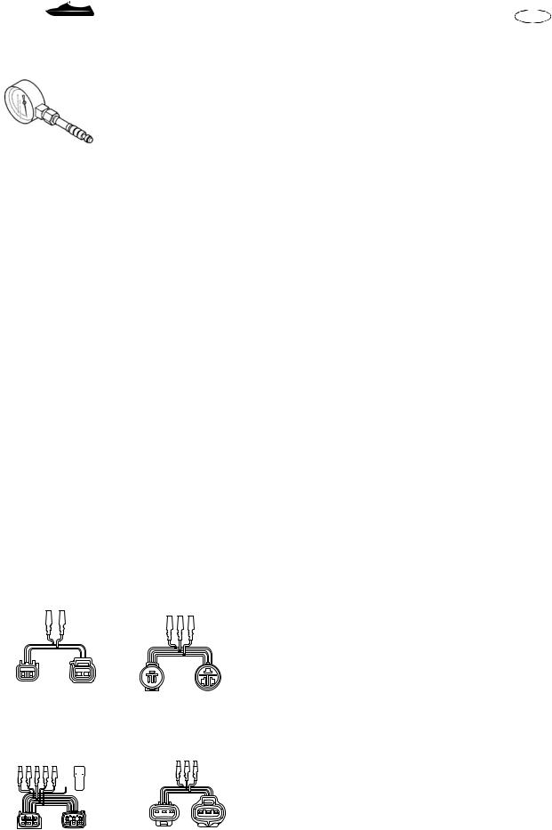
B Fuel pressure gauge |
|
|
|
|
|
|
|
|
|
|
|
|
|
|
|
|
|
|
|
|
|
|
|
|
|
|
|
|
|
|
|
|
|
|
|
|
|
|
|
|
|
|
|
|
|
|
|
|
|
||
B YB-06766 |
|
90890-06786 |
|
|
|
|
|
|
|
|
|
P/N. YB-06766 |
|||||||||||||||||||||||||||||||||||||
|
|
|
|
|
|
|
|
|
|
|
|
|
|
|
|
|
|
|
|
|
|
|
|
|
|
|
|
|
|
|
|
|
|
|
|
|
|
|
|
|
|
|
|
|
|
|
|
90890-06786 |
|
|
|
|
|
|
|
|
|
|
|
|
|
|
|
|
|
|
|
|
|
|
|
|
|
|
|
|
|
|
|
|
|
|
|
|
|
|
|
|
|
|
|
|
|
|
|
|
|
C Compression gauge extension |
|
|
|
|
|
|
|
|
|
|
|
|
|
|
|
|
|
|
|
|
|
|
|
|
|
|
|
|
|
|
|
|
|
|
|
|
|
|
|
|
|
|
|
|
|
|
|
|
|
P/N. 90890-06582 |
|
|
|
|
|
|
|
|
|
|
|
|
|
|
|
|
|
|
|
|
|
|
|
|
|
|
|
|
|
|
|
|
|
|
|
|
|
|
|
|
|
|
|
|
|
|
|
|
|
D Cylinder gauge set |
|
|
|
|
|
|
|
|
|
|
|
|
|
|
|
|
|
|
|
|
|
|
|
|
|
|
|
|
|
|
|
|
|
|
|
|
|
|
|
|
|
|
|
|
|
|
|
|
|
P/N. YU-03017 |
|
C 90890-06582 |
D YU-03017 |
90890-06759 |
|||||||||||||||||||||||||||||||||||||||||||||||
E Compression gauge |
|||||||||||||||||||||||||||||||||||||||||||||||||
|
|
|
|
|
|
|
|
|
|
|
|
|
|
|
|
|
|
|
|
|
|
|
|
|
|
|
|
|
|
|
|
|
|
90890-06759 |
|
|
|
|
|
|
|
|
|
||||||
|
|
|
|
|
|
|
|
|
|
|
|
|
|
|
|
|
|
|
|
|
|
|
|
|
|
|
|
|
|
|
|
|
|
|
|
|
|
|
|
|
|
|
|
|
|
|
|
P/N. YU-33223-1 |
|
|
|
|
|
|
|
|
|
|
|
|
|
|
|
|
|
|
|
|
|
|
|
|
|
|
|
|
|
|
|
|
|
|
|
|
|
|
|
|
|
|
|
|
|
|
|
|
|
90890-03160 |
|
|
|
|
|
|
|
|
|
|
|
|
|
|
|
|
|
|
|
|
|
|
|
|
|
|
|
|
|
|
|
|
|
|
|
|
|
|
|
|
|
|
|
|
|
|
|
|
|
F Peak volt meter adapter |
|
|
|
|
|
|
|
|
|
|
|
|
|
|
|
|
|
|
|
|
|
|
|
|
|
|
|
|
|
|
|
|
|
|
|
|
|
|
|
|
|
|
|
|
|
|
|
|
|
P/N. YU-39991 |
|
|
|
|
|
|
|
|
|
|
|
|
|
|
|
|
|
|
|
|
|
|
|
|
|
|
|
|
|
|
|
|
|
|
|
|
|
|
|
|
|
|
|
|
|
|
|
|
|
G Peak voltage adapter B |
|
E YU-33223-1 |
|
90890-03160 |
|
|
|
|
|
|
|
|
|
P/N. 90890-03172 |
|||||||||||||||||||||||||||||||||||||
|
|
|
|
|
|
|
|
|
|
|
|
|
|
|
|
|
|
|
|
|
|
|
|
|
|
|
|
|
|
|
|
|
|
|
|
|
|
|
|
|
|
|
|
|
|
|
|
H Spark gap tester |
|
|
|
|
|
|
|
|
|
|
|
|
|
|
|
|
|
|
|
|
|
|
|
|
|
|
|
|
|
|
|
|
|
|
|
|
|
|
|
|
|
|
|
|
|
|
|
|
|
P/N. YM-34487 |
|
|
|
|
|
|
|
|
|
|
|
|
|
|
|
|
|
|
|
|
|
|
|
|
|
|
|
|
|
|
|
|
|
|
|
|
|
|
|
|
|
|
|
|
|
|
|
|
|
I Ignition tester |
|
|
|
|
|
|
|
|
|
|
|
|
|
|
|
|
|
|
|
|
|
|
|
|
|
|
|
|
|
|
|
|
|
|
|
|
|
|
|
|
|
|
|
|
|
|
|
|
|
P/N. 90890-06754 |
|
|
|
|
|
|
|
|
|
|
|
|
|
|
|
|
|
|
|
|
|
|
|
|
|
|
|
|
|
|
|
|
|
|
|
|
|
|
|
|
|
|
|
|
|
|
|
|
|
J Test harness (2 pins) |
|
F |
YU-39991 |
G |
90890-03172 |
|
|
|
|
|
|
|
|
|
P/N. New: YB-06867 |
||||||||||||||||||||||||||||||||||||
|
|
|
|
|
|
|
|
|
|
|
|
|
|
|
|
|
|
|
|
|
|
|
|
|
|
|
|
|
|
|
|
|
|
|
|
|
|
|
|
|
|
|
|
|
|
||||
|
|
|
|
|
|
|
|
|
|
|
|
|
|
|
|
|
|
|
|
|
|
|
|
|
|
|
|
|
|
|
|
|
|
|
|
|
|
|
|
|
|
|
|
|
|
|
|
Current: YB-06767 |
|
|
|
|
|
|
|
|
|
|
|
|
|
|
|
|
|
|
|
|
|
|
|
|
|
|
|
|
|
|
|
|
|
|
|
|
|
|
|
|
|
|
|
|
|
|
|
|
|
Test harness FWY-2 (2 pins) |
|
|
|
|
|
|
|
|
|
|
|
|
|
|
|
|
|
|
|
|
|
|
|
|
|
|
|
|
|
|
|
|
|
|
|
|
|
|
|
|
|
|
|
|
|
|
|
|
|
P/N. New: 90890-06867 |
|
|
|
|
|
|
|
|
|
|
|
|
|
|
|
|
|
|
|
|
|
|
|
|
|
|
|
|
|
|
|
|
|
|
|
|
|
|
|
|
|
|
|
|
|
|
|
|
|
Current: 90890-06767 |
|
|
|
|
|
|
|
|
|
|
|
|
|
|
|
|
|
|
|
|
|
|
|
|
|
|
|
|
|
|
|
|
|
|
|
|
|
|
|
|
|
|
|
|
|
|
|
|
|
K Test harness (3 pins) |
|
H YM-34487 |
I 90890-06754 |
P/N. New: YB-06870 |
|||||||||||||||||||||||||||||||||||||||||||||||
|
|
|
|
|
|
|
|
|
|
|
|
|
|
|
|
|
|
|
|
|
|
|
|
|
|
|
|
|
|
|
|
|
|
|
|
|
|
|
|
|
|
|
|
|
|
|
|
Current: YB-06770 |
|
|
|
|
|
|
|
|
|
|
|
|
|
|
|
|
|
|
|
|
|
|
|
|
|
|
|
|
|
|
|
|
|
|
|
|
|
|
|
|
|
|
|
|
|
|
|
|
|
Test harness SMT250-3 (3 pins) |
|
|
|
|
|
|
|
|
|
|
|
|
|
|
|
|
|
|
|
|
|
|
|
|
|
|
|
|
|
|
|
|
|
|
|
|
|
|
|
|
|
|
|
|
|
|
|
|
|
P/N. New: 90890-06870 |
|
|
|
|
|
|
|
|
|
|
|
|
|
|
|
|
|
|
|
|
|
|
|
|
|
|
|
|
|
|
|
|
|
|
|
|
|
|
|
|
|
|
|
|
|
|
|
|
|
Current: 90890-06770 |
|
|
|
|
|
|
|
|
|
|
|
|
|
|
|
|
|
|
|
|
|
|
|
|
|
|
|
|
|
|
|
|
|
|
|
|
|
|
|
|
|
|
|
|
|
|
|
|
|
L Test harness (6 pins) |
|
J YB-06867 (-06767) |
K YB-06870 (-06770) |
P/N. YB-06848 |
|||||||||||||||||||||||||||||||||||||||||||||||
Test harness FSW-6A (6 pins) |
|||||||||||||||||||||||||||||||||||||||||||||||||
|
90890-06867 (-06767) |
|
|
90890-06870 (-06770) |
|||||||||||||||||||||||||||||||||||||||||||||
|
|
|
|
|
|
|
|
|
|
|
|
|
|
|
|
|
|
|
|
|
|
|
|
|
|
|
|
|
|
|
|
|
|
|
|
|
|
|
|
|
|
|
|
|
|
|
|
P/N. 90890-06848 |
|
|
|
|
|
|
|
|
|
|
|
|
|
|
|
|
|
|
|
|
|
|
|
|
|
|
|
|
|
|
|
|
|
|
|
|
|
|
|
|
|
|
|
|
|
|
|
|
|
M Test harness (3 pins) |
|
|
|
|
|
|
|
|
|
|
|
|
|
|
|
|
|
|
|
|
|
|
|
|
|
|
|
|
|
|
|
|
|
|
|
|
|
|
|
|
|
|
|
|
|
|
|
|
|
||
|
|
|
|
|
|
|
|
|
|
|
|
|
|
|
|
|
|
|
|
|
|
|
|
|
|
|
|
|
|
|
|
|
|
|
|
|
|
|
|
|
|
|
|
|
|
|
|
||
|
|
|
|
|
|
|
|
|
|
|
|
|
|
|
|
|
|
|
|
|
|
|
|
|
|
|
|
|
|
|
|
|
|
|
|
|
|
|
|
|
|
|
|
|
|
|
|
P/N. YB-06793 |
|
|
|
|
|
|
|
|
|
|
|
|
|
|
|
|
|
|
|
|
|
|
|
|
|
|
|
|
|
|
|
|
|
|
|
|
|
|
|
|
|
|
|
|
|
|
|
|
|
Test harness SMHW099-3 (3 pins) |
|
|
|
|
|
|
|
|
|
|
|
|
|
|
|
|
|
|
|
|
|
|
|
|
|
|
|
|
|
|
|
|
|
|
|
|
|
|
|
|
|
|
|
|
|
|
|
|
|
P/N. 90890-06793 |
|
L YB-06848 |
M YB-06793 |
|
|||||||||||||||||||||||||||||||||||||||||||||||
|
90890-06848 |
|
|
|
|
|
|
|
|
|
|
90890-06793 |
|
|
|
|
|
|
|
|
|
|
|||||||||||||||||||||||||||
|
|
|
|
|
|
|
|
|
|
|
|
|
|
|
|
|
|
|
|
|
|
|
|
|
|
|
|
|
|
|
|
|
|
|
|
|
|
|
|
|
|
|
|
|
|
|
|
|
|
|
|
|
|
|
|
|
|
|
|
|
|
|
|
|
|
|
|
|
|
|
|
|
|
|
|
|
|
|
|
|
|
|
|
|
|
|
|
|
|
|
|
|
|
|
|
|
|
|
|
|
|
|
|
|
|
|
|
|
|
|
|
|
|
|
|
|
|
|
|
|
|
|
|
|
|
|
|
|
|
|
|
|
|
|
|
|
|
|
|
|
|
|
|
|
|
|
|
|
|
|
|
|
|
|
|
|
|
|
|
|
|
|
|
|
|
|
|
|
|
|
|
|
|
|
|
|
|
|
|
|
|
|
|
|
|
|
|
|
|
|
|
|
|
|
|
|
|
|
|
1-6

GEN INFO
OUTILS SPECIAUX |
F |
|
D |
|
|
SPEZIALWERKZEUGE |
|
|
HERRAMIENTAS ESPECIALES |
ES |
|
|
|
|
BManomètre de carburant P/N. YB-06766
90890-06786
CRallonge de compressiomètre P/N. 90890-06582
DComparateur pour cylindre P/N. YU-03017
90890-06759
ECompressiomètre P/N. YU-33223-1
90890-03160
FAdaptateur de tension de crête P/N. YU-39991
GAdaptateur B de tension de crête P/N. 90890-03172
HTesteur d’allumage P/N. YM-34487
IVérificateur d’allumage P/N. 90890-06754
JFaisceau de test (2 broches) P/N. Nouveau: YB-06867
Actuel: YB-06767 Faisceau de test FWY-2 (2 broches)
P/N. Nouveau: 90890-06867 Actuel: 90890-06767
KFaisceau de test (3 broches) P/N. Nouveau: YB-06870
Actuel: YB-06770 Faisceau de test SMT250-3 (3 broches)
P/N. Nouveau: 90890-06870 Actuel: 90890-06770
LFaisceau de test (6 broches) P/N. YB-06848
Faisceau de test FSW-6A (6 broches)
P/N. 90890-06848
MFaisceau de test (3 broches) P/N. YB-06793
Faisceau de test SMHW099-3 (3 broches)
P/N. 90890-06793
BKraftstoffdruckmesser P/N. YB-06766
90890-06786
CKompressionsmesser-Verlän- gerungsstück
P/N. 90890-06582
DZylinder-Meßuhrsatz P/N. YU-03017
90890-06759
EKompressionsmesser P/N. YU-33223-1
90890-03160
FAdapter für den Spitzenspannungsmesser
P/N. YU-39991
GMeßadapter B für Spitzenspannung
P/N. 90890-03172
HElektrodenabstand-Prüfer P/N. YM-34487
IZündfunkentester P/N. 90890-06754
JPrüfkabelbaum (2 Pole) P/N. Neu: YB-06867
Laufend: YB-06767 Prüfkabelbaum FWY-2 (2 Pole) P/N. Neu: 90890-06867
Laufend: 90890-06767
KPrüfkabelbaum (3 Pole) P/N. Neu: YB-06870
Laufend: YB-06770 Prüfkabelbaum SMT250-3 (3 Pole)
P/N. Neu: 90890-06870 Laufend: 90890-06770
LPrüfkabelbaum (6 Pole) P/N. YB-06848 Prüfkabelbaum FSW-6A (6 Pole)
P/N. 90890-06848
MPrüfkabelbaum (3 Pole) P/N. YB-06793 Prüfkabelbaum SMHW099-3 (3 Pole)
P/N. 90890-06793
BManómetro de combustible P/N.º YB-06766
90890-06786
CExtensión de compresímetro P/N.º 90890-06582
DJuego de galgas de cilindros P/N.º YU-03017
90890-06759
ECompresímetro P/N.º YU-33223-1
90890-03160
FAdaptador de voltímetro de picos P/N.º YU-39991
GAdaptador de tensión pico B P/N.º 90890-03172
HProbador de huelgo de bujías P/N.º YM-34487
IComprobador de encendido P/N.º 90890-06754
JConector de prueba (2 clavijas) P/N.º Nuevo: YB-06867
Actual: YB-06767 Conector de prueba FWY-2 (2 clavijas)
P/N.º Nuevo: 90890-06867 Actual: 90890-06767
KConector de prueba (3 clavijas) P/N.º Nuevo: YB-06870
Actual: YB-06770 Conector de prueba SMT250-3 (3 clavijas)
P/N.º Nuevo: 90890-06870 Actual: 90890-06770
LConector de prueba (6 clavijas) P/N.º YB-06848
Conector de prueba FSW-6A (6 clavijas)
P/N.º 90890-06848
MConector de prueba (3 clavijas) P/N.º YB-06793
Conector de prueba SMHW099-3 (3 clavijas)
P/N.º 90890-06793
1-6

GEN |
SPECIAL TOOLS |
|
INFO |
E |
|
|
|
N Test harness (3 pins) |
N YB-06877 (-06777) |
O YB-35956-A |
P/N. New: YB-06877 |
90890-06877 (-06777) |
90890-06756 |
Current: YB-06777 |
|
|
|
|
|
Test harness HM090-3 (3 pins) |
|
|
P/N. New: 90890-06877 |
|
|
Current: 90890-06777 |
|
|
O Lower unit pressure/vacuum tester |
|
|
P/N. YB-35956-A |
|
|
Vacuum/pressure pump gauge set |
|
|
P/N. 90890-06756 |
P 60V-85300-02 |
|
P Yamaha diagnostic system |
|
|
P/N. 60V-85300-02 |
|
|
Q Yamaha diagnostic system |
|
|
P/N. 60V-WS853-02 |
Q 60V-WS853-02
YAMAHA
DIAGNOSTIC
SYSTEM
INSTALLATION MANUAL
|
|
REMOVAL AND INSTALLATION |
|
1 YU-38411 |
2 YW-06551 |
1 |
Oil filter wrench |
90890-01426 |
|
|
P/N. YU-38411 |
|
|
|
|
|
90890-06551 |
|
90890-01426 |
|
|
2 |
Coupler wrench |
|
|
|
P/N. YW-06551 |
|
|
|
90890-06551 |
|
|
3 |
Sheave holder |
|
|
|
P/N. YS-01880-A |
|
|
|
90890-01701 |
3 YS-01880-A |
4 YM-01082 |
4 |
Rotor puller |
|
P/N. YM-01082 |
||
90890-01701 |
90890-01080 |
|
|
|
|
|
90890-01080 |
|
|
|
|
1-7

GEN INFO
OUTILS SPECIAUX |
F |
|
D |
|
|
SPEZIALWERKZEUGE |
|
|
HERRAMIENTAS ESPECIALES |
ES |
|
|
|
|
N Faisceau de test (3 broches) |
N Prüfkabelbaum (3 Pole) |
N Conector de prueba (3 clavijas) |
|
P/N. Nouveau: YB-06877 |
P/N. Neu: YB-06877 |
P/N.º Nuevo: YB-06877 |
|
Actuel: YB-06777 |
Laufend: YB-06777 |
Actual: YB-06777 |
|
Faisceau de test HM090-3 |
Prüfkabelbaum HM090-3 |
Conector de prueba HM090-3 |
|
(3 broches) |
(3 Pole) |
(3 clavijas) |
|
P/N. Nouveau: 90890-06877 |
P/N. Neu: 90890-06877 |
P/N.º Nuevo: 90890-06877 |
|
Actuel: 90890-06777 |
Laufend: 90890-06777 |
Actual: 90890-06777 |
|
O Testeur de pression/dépression |
O Druck/Unterdruck-Prüfgerät des |
O Manómetro/vacuómetro de unidad |
|
d’unité inférieure |
Unterwasserteils |
inferior |
|
P/N. YB-35956-A |
P/N. YB-35956-A |
P/N.º YB-35956-A |
|
Ensemble dépressiomètre/ |
Meßsatz der Druck-/Unter- |
Conjunto de vacuómetro/ |
|
manomètre |
druckpumpe |
manómetro para la bomba |
|
P/N. 90890-06756 |
P/N. 90890-06756 |
P/N.º 90890-06756 |
|
P Système de diagnostic Yamaha |
P Yamaha Diagnosesystem |
P Sistema de diagnósticos de |
|
P/N. 60V-85300-02 |
P/N. 60V-85300-02 |
Yamaha |
|
Q Système de diagnostic Yamaha |
Q Yamaha Diagnosesystem |
P/N.º 60V-85300-02 |
|
|
|||
P/N. 60V-WS853-02 |
Erweiterung |
Q Sistema de diagnósticos de |
|
DEPOSE ET INSTALLATION |
P/N. 60V-WS853-02 |
Yamaha |
|
|
P/N.º 60V-WS853-02 |
||
1 Clé pour filtre à huile |
AUSBAU UND EINBAU |
||
|
|||
P/N. YU-38411 |
1 Ölfilterschlüssel |
DESMONTAJE Y MONTAJE |
|
90890-01426 |
P/N. YU-38411 |
1 Llave para filtro de aceite |
|
2 Clé d’accouplement |
90890-01426 |
P/N.º YU-38411 |
|
|
90890-01426 |
||
P/N. YW-06551 |
2 Kopplungsschlüssel |
||
|
|||
90890-06551 |
P/N. YW-06551 |
2 Llave del acoplador |
|
3 Outil de maintien de poulie |
90890-06551 |
P/N.º YW-06551 |
|
|
90890-06551 |
||
P/N. YS-01880-A |
3 Riemenscheibenhalter |
||
|
|||
90890-01701 |
P/N. YS-01880-A |
3 Sujetador de discos |
|
4 Extracteur de rotor |
90890-01701 |
P/N.º YS-01880-A |
|
|
90890-01701 |
||
P/N. YM-01082 |
4 Laufradzieher |
||
|
|||
90890-01080 |
P/N. YM-01082 |
4 Extractor de rotores |
|
|
90890-01080 |
P/N.º YM-01082 |
|
|
|
90890-01080 |
1-7
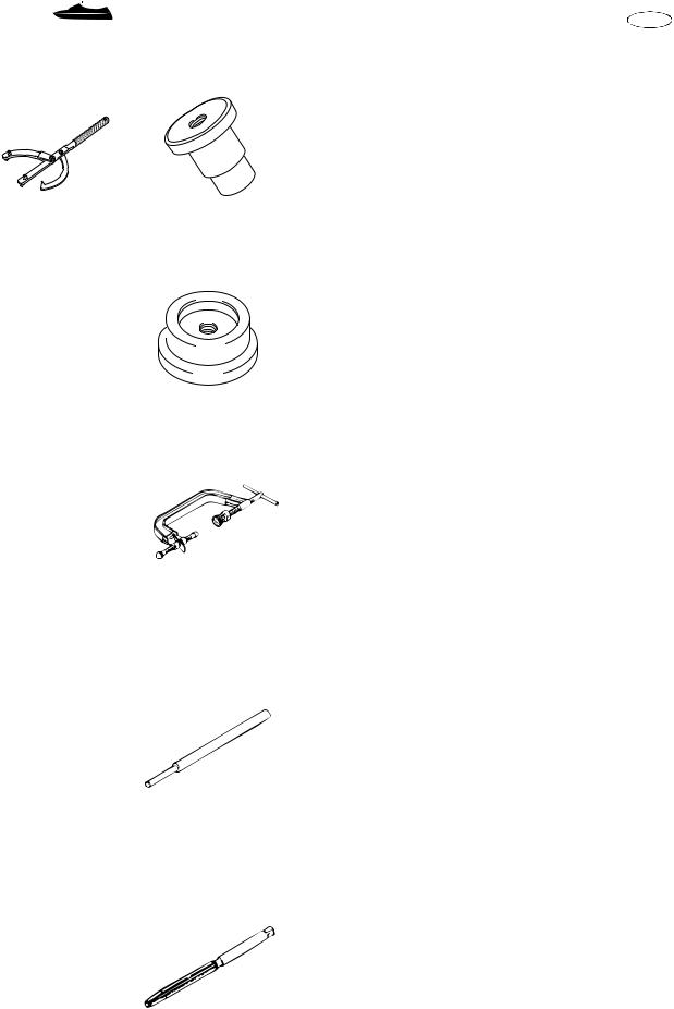
GEN |
|
|
SPECIAL TOOLS |
|
|
|||
INFO |
|
|
|
E |
||||
|
|
|
|
|
|
5 |
Universal magneto and rotor holder |
|
|
|
|
|
|
|
|||
5 YU-01235 |
6 YB-06111 |
|
P/N. YU-01235 |
|||||
90890-01235 |
|
|
|
|
|
Rotor holder |
||
|
|
|
|
|
|
|
||
|
|
|
|
|
|
|
P/N. 90890-01235 |
|
|
|
|
|
|
|
6 |
Bearing housing needle bearing installer |
|
|
|
|
|
|
|
|
(reduction drive gear) |
|
|
|
|
|
|
|
|
P/N. YB-06111 |
|
|
|
|
|
|
|
7 |
Ball bearing attachment |
|
|
|
|
|
|
|
|
(reduction drive gear) |
|
|
|
|
|
|
|
|
P/N. 90890-06631 |
|
7 90890-06631 |
|
|
8 YB-06726-B |
8 |
Forward gear bearing cup installer |
|||
|
|
|
|
|
|
|
(reduction drive gear) |
|
|
|
|
|
|
|
|
P/N. YB-06726-B |
|
|
|
|
|
|
|
9 |
Ball bearing attachment |
|
|
|
|
|
|
|
|||
|
|
|
|
|
|
|
(reduction drive gear) |
|
|
|
|
|
|
|
|
||
|
|
|
|
|
|
|
P/N. 90890-06657 |
|
|
|
|
|
|
|
0 |
Valve spring compressor |
|
|
|
|
|
|
|
|
P/N. YM-01253 |
|
|
|
|
|
|
|
|
90890-04019 |
|
9 90890-06657 |
|
|
0 YM-01253 |
A Valve spring compressor attachment |
||||
|
|
|
|
90890-04019 |
|
P/N. YM-4114 (ø19 mm) |
||
|
|
|
|
|
|
|
||
|
|
|
|
|
|
|
90890-04114 (ø19 mm) |
|
|
|
|
|
|
|
|
YM-4108 (ø22 mm) |
|
|
|
|
|
|
|
|
90890-04108 (ø22 mm) |
|
|
|
|
|
|
|
B Valve guide remover |
||
|
|
|
|
|
|
|
P/N. YM-04111 (ø4.0 mm) |
|
|
|
|
|
|
|
|
90890-04111 (ø4.0 mm) |
|
|
|
|
|
|
|
|
YM-04116 (ø4.5 mm) |
|
A YM-4114 (ø19 mm) |
B YM-04111 (ø4.0 mm) |
|
90890-04116 (ø4.5 mm) |
|||||
C Valve guide installer |
||||||||
90890-04114 (ø19 mm) |
90890-04111 (ø4.0 mm) |
|||||||
YM-4108 (ø22 mm) |
YM-04116 (ø4.5 mm) |
|
P/N. YM-04112 (ø4.0 mm) |
|||||
90890-04108 (ø22 mm) |
90890-04116 (ø4.5 mm) |
|
90890-04112 (ø4.0 mm) |
|||||
|
|
|
|
|
|
|
||
|
|
|
|
|
|
|
YM-04117 (ø4.5 mm) |
|
|
|
|
|
|
|
|
90890-04117 (ø4.5 mm) |
|
|
|
|
|
|
|
D Valve guide reamer |
||
|
|
|
|
|
|
|
P/N. YM-04113 (ø4.0 mm) |
|
|
|
|
|
|
|
|
90890-04113 (ø4.0 mm) |
|
|
|
|
|
|
|
|
YM-04118 (ø4.5 mm) |
|
|
|
|
|
|
|
|
90890-04118 (ø4.5 mm) |
|
C YM-04112 (ø4.0 mm) |
D YM-04113 (ø4.0 mm) |
|
|
|||||
90890-04112 (ø4.0 mm) |
90890-04113 (ø4.0 mm) |
|
|
|||||
YM-04117 (ø4.5 mm) |
YM-04118 (ø4.5 mm) |
|
|
|||||
90890-04117 (ø4.5 mm) |
90890-04118 (ø4.5 mm) |
|
|
|||||
|
|
|
|
|
|
|
|
|
1-8
 Loading...