


FJR1300AP
SUPPLEMENTARY MANUAL FOR POLICE VERSION SUPPLEMENT AU MANUEL POUR LE MODELE DE POLICE ERGÄNZENDE WARTUNGSANLEITUNG FÜR POLIZEI-MODELL MANUALE SUPPLEMENTARE PER LA VERSIONE PER LA POLIZIA MANUAL SUPLEMENTARIO PARA LA VERSIÓN DE POLICÍA
5P5-28199-51

SUPPLEMENTARY MANUAL FOR POLICE VERSION
SUPPLEMENT AU MANUEL POUR LE MODELE DE POLICE
ERGÄNZENDE WARTUNGSANLEITUNG FÜR POLIZEIMODELL
MANUALE SUPPLEMENTARE PER LA VERSIONE PER LA POLIZIA
MANUAL SUPLEMENTARIO PARA LA VERSIÓN DE POLICÍA
WIRING DIAGRAM / SCHÉMA DE CÂBLAGE / SCHALTPLAN / SCHEMA ELETTRICO / DIAGRAMA ELÉCTRICO

INTRODUCTION
This supplementary manual has been prepared to introduce new service and new service and new data for the FJR1300AP. For complete information on service procedures, it is necessary to use this manual together with following manuals:
FJR1300 OWNER’S MANUAL (5P5-28199-E2, -F2, -G2, -H2, -S2)
FJR1300 SERVICE MANUAL (3P6-28197-E2, -F2, -G2, -H2, -S2)
FJR1300AP
SUPPLEMENTARY MANUAL
FOR POLICE VERSION
2008 Yamaha Motor Co., Ltd.
1 st Edition, March 2008
All right reserved. Any reprinting or unauthorized use without the written permission of Yamaha Motor Co., Ltd. is expressly prohibited.
Printed in Japan

IMPORTANT MANUAL INFORMATION
Particularly important information is distinguished in this manual by the following notations:
The Safety Alert Symbol means ATTENTION! BECOME ALERT! YOUR SAFETY IS INVOLVED!
Failure to follow WARNING instructions could result in severe injury or death to the motorcycle operator, a bystander, or a person inspecting or repairing the motorcycle.
A CAUTION indicates special precautions that must be taken to avoid damage to the motorcycle.
NOTE:
A NOTE provides key information to make procedures easier or clearer.
NOTE:
Yamaha continually seeks advancements in product design and quality. Therefore, while this manual contains the most current product information available at the time of printing, there may be minor discrepancies between your motorcycle and this manual. If you have any questions concerning this manual, please consult your Yamaha dealer.
CONTENTS |
|
DESCRIPTION------------------------------------------------------------------------------------------------ |
1 |
SPECIFICATIONS ------------------------------------------------------------------------------------------- |
1 |
INSTRUMENT AND CONTROL FUNCTIONS ------------------------------------------------------- |
2 |
RIGHT HANDLEBAR SWITCH ---------------------------------------------------------------------- |
2 |
RADIO BOX (5P56, 5P57) ---------------------------------------------------------------------------- |
3 |
CHANGEOVER OF COUPLERS FOR REAR TURN SIGNAL LIGHTS ------------------- |
4 |
SUSPENSION SETTINGS ---------------------------------------------------------------------------- |
4 |
MAINTENANCE ---------------------------------------------------------------------------------------------- |
5 |
TIGHTENING TORQUE -------------------------------------------------------------------------------- |
5 |
CABLE ROUTING DIAGRAM ------------------------------------------------------------------------ |
7 |
CHECKING THE ELECTRICAL COMPONENTS --------------------------------------------- |
15 |
WIRING DIAGRAM |
|

DESCRIPTION / SPECIFICATIONS
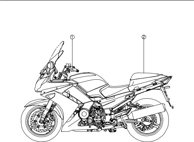
DESCRIPTION
 Patrol switch
 Radio box (5P56, 5P57)
SPECIFICATIONS
Model name |
FJR1300AP |
FJR1300AP |
FJR1300AP |
|
|
|
|
Approved model type |
RP13 |
← |
← |
Registered model type |
5P55 |
5P56 |
5P57 |
|
|
|
|
Overall length (mm) |
2230 |
← |
← |
Overall width (mm) |
740 |
← |
← |
Overall height (mm) |
1315 |
← |
← |
Ground clearance (mm) |
130 |
← |
← |
Weight (kg) |
264 |
← |
← |
-1-
INSTRUMENT AND CONTROL FUNCTIONS
INSTRUMENT AND
CONTROL FUNCTIONS
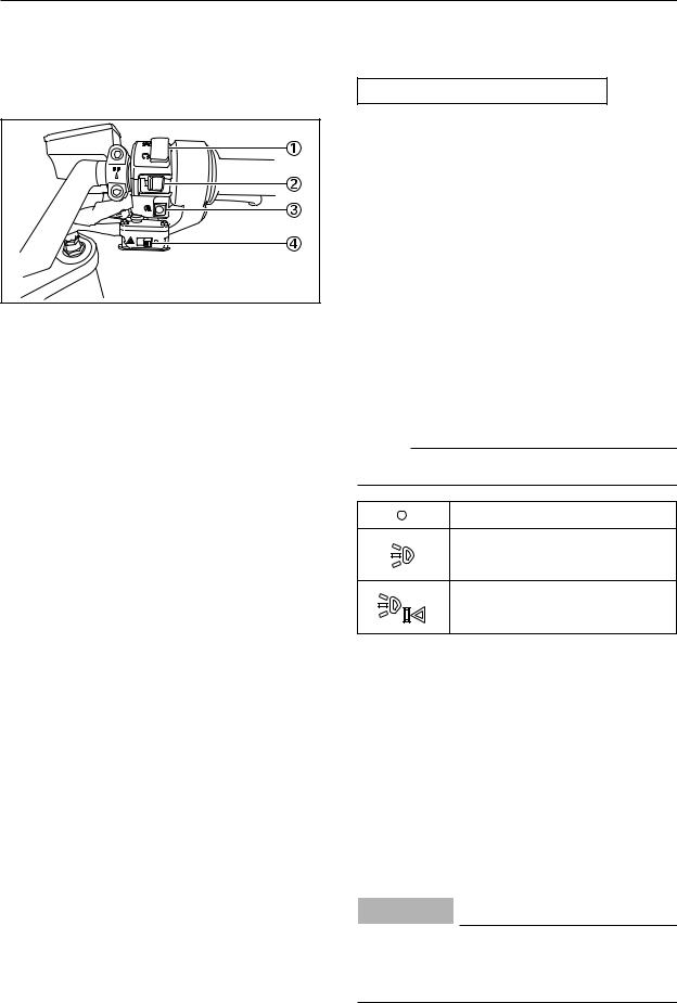
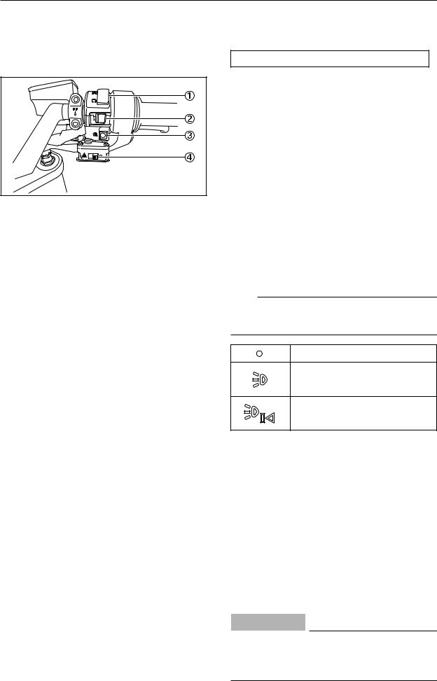
RIGHT HANDLEBAR SWITCH
 Engine stop switch
 Patrol switch
 Start switch
 Hazard switch
ENGINE STOP SWITCH
Set this switch to " " before starting the engine. Set this switch to "
 " to stop the engine in case of an emergency, such as when the motorcycle overturns or when the throttle cable is stuck.
PATROL SWITCH
This switch activates the siren or flashing lamp.
NOTE:
It is used when a siren or flashing lamp is installed.
OFF
This is for the flashing lamp.
This is for both siren and flashing lamp.
START SWITCH
Push this switch to crank the engine with the starter.
HAZARD SWITCH
With the key in the "ON" or "P" position, use this switch to turn on the hazard lights (simultaneous flashing of all turn signal lights).
The hazard lights are used in case of an emergency or to warn other drivers when your vehicle is stopped where it might be a traffic hazard.
CAUTION:
Do not use the hazard lights for an extended length of time with the engine not running, otherwise the battery may discharge.
-2-

INSTRUMENT AND CONTROL FUNCTIONS
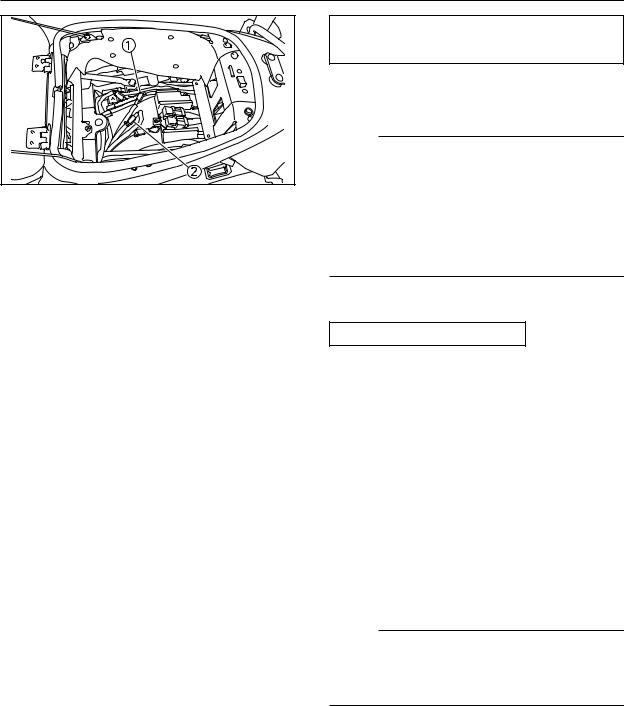
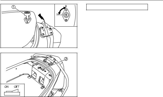
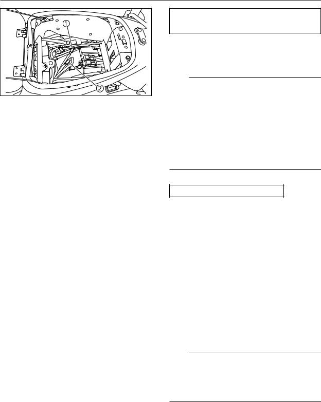
RADIO BOX (5P56, 5P57)
The lid can be locked by turning the inserted key  . [a] LOCK
[b] OPEN
• Changeover of the position of the switch can prevent the battery from being discharged.
ON : When an auxiliary instrument is used
OFF : When no auxiliary instruments are used
-3-
INSTRUMENT AND CONTROL FUNCTIONS
CHANGEOVER OF COUPLER FOR REAR
TURN SIGNAL LIGHTS
When a rear pole set (option) is installed to the motorcycle, this blue coupler  is used.
NOTE:
Changeover of the wire harness connection can determine which lamp to light up.
•Connect to blue coupler  : Rear turn signal lights on the rear pole set side turn on.
•Connect to white coupler  : Rear turn signal lights in the rear combination lamps turn on.
SUSPENSION SETTINGS
When the motorcycle gains weight with auxiliary instruments installed, perform the settings by reference to the following:
1.Front fork
•Increase pre-load.
•Decrease the rebound damping force (when pre-load is increased).
•Decrease the compression damping force (when pre-load is increased).
2.Rear suspension
•Increase pre-load (from soft to stiff)
•No change in the rebound damping force
NOTE:
The above settings are just a rule of thumb. They vary with the rider’s weight etc., so get the feeling in an actual run.
-4-

MAINTENANCE
MAINTENANCE
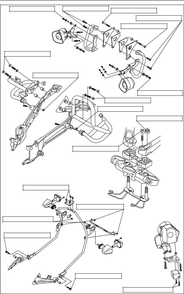
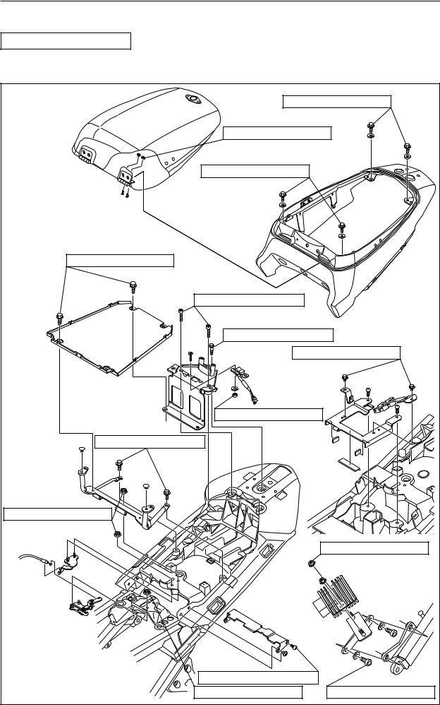
TIGHTENING TORQUE
Check each of the installed parts for any looseness during motorcycle inspection.
7 Nm (0.7 m • kg, 5.1 ft • lb) |
|
2 Nm (0.2 m • kg, 1.4 ft • lb) |
|
7 Nm (0.7 m • kg, 5.1 ft • lb) |
|
7 Nm (0.7 m • kg, 5.1 ft • lb) |
|
21 Nm (2.1 m • kg, 15 ft • lb) |
|
21 Nm (2.1 m • kg, 15 ft • lb) |
|
7 Nm (0.7 m • kg, 5.1 ft • lb) |
|
4 Nm (0.4 m • kg, 2.9 ft • lb) |
|
16 Nm (1.6 m • kg, 11 ft • lb) |
|
7 Nm (0.7 m • kg, 5.1 ft • lb) |
|
|
7 Nm (0.7 m • kg, 5.1 ft • lb) |
1.5 Nm (0.15 m • kg, 1.1 ft • lb) |
|
7 Nm (0.7 m • kg, 5.1 ft • lb) |
8 Nm (0.8 m • kg, 5.8 ft • lb) |
-5- |
|
|
|
MAINTENANCE |
7 Nm (0.7 m • kg, 5.1 ft • lb) |
64 Nm (6.4 m • kg, 46 ft • lb) |
49 Nm (4.9 m • kg, 35 ft • lb) |
|
|
|
|
|
64 Nm (6.4 m • kg, 46 ft • lb) |
|
|
49 Nm (4.9 m • kg, 35 ft • lb) |
28 Nm (2.8 m • kg, 20 ft • lb) |
|
|
9 Nm (0.9 m • kg, 6.5 ft • lb) |
|
|
|
|
7 Nm (0.7 m • kg, 5.1 ft • lb) |
|
28 Nm (2.8 m • kg, 20 ft • lb) |
|
|
9 Nm (0.9 m • kg, 6.5 ft • lb) |
|
|
|
65 Nm (6.5 m • kg, 47 ft • lb) |
|
23 Nm (2.3 m • kg, 17 ft • lb) |
|
29 Nm (2.9 m • kg, 21 ft • lb) |
|
|
|
10 Nm (1.0 m • kg, 7.2 ft • lb) |
|
1.5 Nm (0.15 m • kg, 1.1 ft • lb) |
|
|
25 Nm (2.5 m • kg, 18 ft • lb) |
|
|
|
25 Nm (2.5 m • kg, 18 ft • lb) |
|
|
|
1.5 Nm (0.15 m • kg, 1.1 ft • lb) |
|
-6- |
|
|
|
MAINTENANCE |
|
|
|
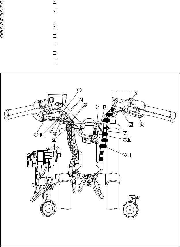
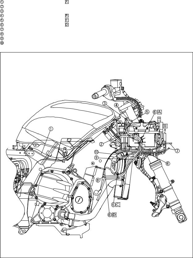
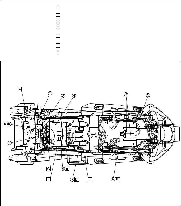
CABLE ROUTING DIAGRAM |
|
|
Right grip warmer lead |
Route the hazard switch lead, right handlebar switch lead and grip warmer lead under the |
|
Right handlebar switch lead |
handlebar. |
|
Front brake hose |
Route the hazard switch lead and grip warmer lead over the right handlebar switch lead |
|
Guide |
while taking care not to have them pinched between the guide and right handlebar switch |
|
Left handlebar switch lead |
lead. |
|
Left grip warmer lead |
Route the left handlebar switch lead and the grip warmer lead under the handlebar. |
|
Clamp |
Pass the clutch hose, the handlebar switch leads (left and right), the grip warmer leads |
|
Throttle cable 1 |
(left and right) and the hazard switch lead through the guide. |
|
Throttle cable 2 |
Clamp the hazard switch lead and right handlebar switch lead. Do not clamp the grip |
|
|
warmer lead. |
|


 Clamp the hazard switch lead, right handlebar switch lead, grip warmer lead, main switch lead and immobilizer unit lead.


 Pass the front brake hose, the right handlebar switch lead, the right grip warmer lead, the hazard switch lead, the throttle cable1 and 2 through the guide.


 Clamp the grip warmer lead on the throttle cable1 and 2. Fasten the clamp where 10 mm inside of the rubber boot end and cut off the clamp end.
-7- |
|
MAINTENANCE |
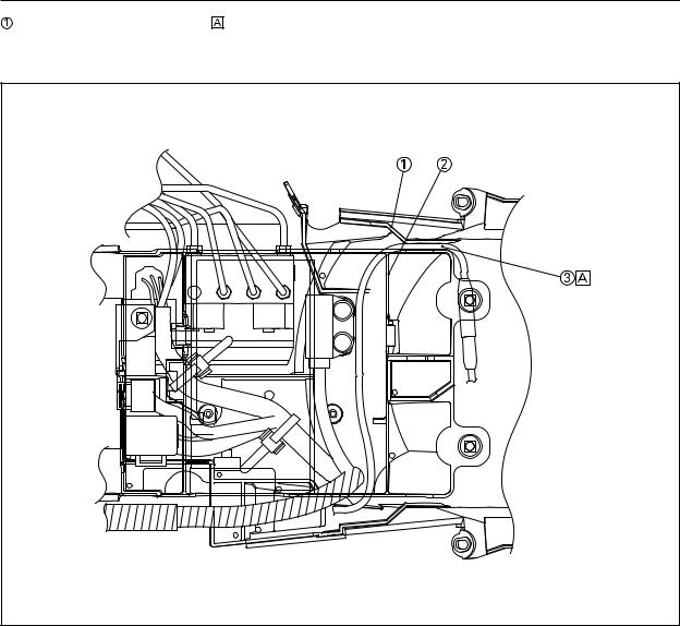
Extension wire lead |
Clamp the wire lead, the negative battery lead, the starter motor lead on the battery |
Wire lead (for battery charging) |
box. Clamp the wire lead on the white tape marking section and turn the clamp end |
Negative lead (for battery charging) |
toward the rear. |
Coupler (for battery charging) |
To the headlight lead |
Fuse (SUB) |
Clamp at the white tape. |
Clamp |
Route the wire harness along the front side of the frame and clamp the white tape |
Wire harness |
marking section of harness at the top of the hole in the frame. |
Coupler (for siren) |
|
Negative battery lead |
|
Starter motor lead |
|
-8- |
|
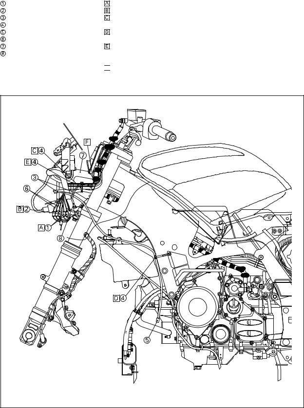
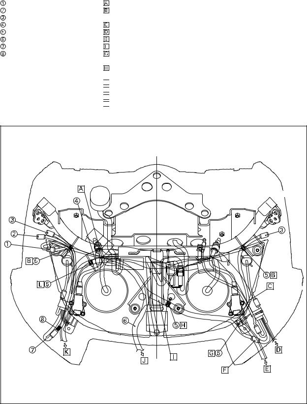
MAINTENANCE |
Right handlebar switch lead |
Connect the right handlebar switch lead to the wire harness. |
Hazard switch lead |
Connect the hazard switch lead to the wire harness. |
Wire harness |
Clamp the wire harness, hazard switch lead, handlebar switch lead and grip warmer |
Clamp |
lead. Do not clamp the front wheel sensor lead. |
Coupler (for siren) |
Route the wire harness along the front side of the frame and clamp the white tape |
Grip warmer lead |
marking section of harness at the top of the hole in the frame. |
Stay |
Clamp the handlebar switch lead, the grip warmer lead and the hazard switch lead, |
Front wheel sensor lead |
and pass them through the hole of the stay. Set the clamp end downward without |
|
cutting it off. |


 Clamp the handlebar switch lead, the grip warmer lead, front wheel sensor lead and the hazard switch lead, and pass them through the hole of the stay. Set the clamp end downward without cutting it off.
-9- |
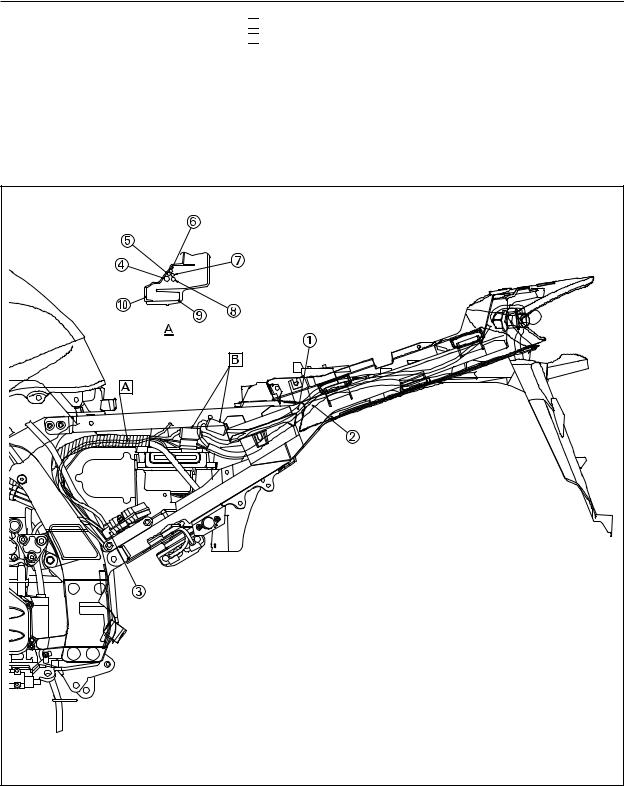
MAINTENANCE
 Wire lead
 Rear combination light lead
 Rectifier
 Rear combination light lead
 License plate light lead
 Sub-lead wire
 Wire lead
 Wire harness assembly
 Rear frame
  Rear fender
 Route the rectifier lead inside the main harness.

 Connect the wire lead between the main harness and rear combination light.
-10-
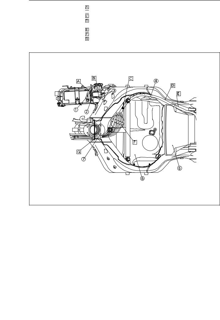
MAINTENANCE
 Coupler (for battery charging)
 Negative lead (for battery charging)

 Fuse box
 Extension wire lead
 Air filter case
 Insulator
  Wire harness
Route the wire lead through the clearance between the battery and fuse box.
Install the fuse (SUB) in the inner fuse box inserting it from underneath.
Align the white taped portion with the front edge of the T-bar.
In installing the fuel tank, take care not to have the extension wire lead pinched between the fuel tank and frame.
Route the extension wire lead along the side of the air filter case. Connect the connectors of the identical color.
Route the wire harness through the hole in the frame to the left of the head pipe and over the insulator.
SUB |
-11-
MAINTENANCE
 Fuel tank fitting bracket
 Seat bracket
 Relay
Relay
 Sub-battery box
 Coupler (for radio box)
 Wire lead
 Wire harness assembly
 Sub-lead wire
 Tool band
  Fuse (PATROL)


 Route the extension wire lead in the middle under the tank fitting bracket and seat bracket.


 Route the wire lead along and over the rear combination light lead.


 Route the wire lead under the sub-battery box.


 Route the wire harness assembly outside the sub-battery box.


 Route the sub-lead wire inside the sub-battery box.


 Connect the sub-lead wire to the wire harness assembly. Place the coupler under the wire harness assembly.


 Connect the couplers of the identical color.


 To the rectifier


 To the relay


 To the fuse


 Insert the fuse (PATROL) into the stay.
-12-
MAINTENANCE
Fender |
Route the seat lock cable between the fender and the box, and pass it under the box. |
 Box
Box
 Seat lock cable
-13-
|
MAINTENANCE |
Coupler (for siren controller) |
Route the wire harness at the back of the headlight beam adjusting cable. |
Coupler (for microphone) |
Route the wire harness along the bottom of the square pipe frame and clamp it at the |
Coupler (front flashing light) |
white tape. Direct the clamp end downward. |
Headlight beam adjusting cable |
Route the wire harness just at the head. |
Clamp |
To the turn signal light and horn |
Wire harness |
To the main battery, including the siren, etc. |
Right handlebar switch lead |
Connect the headlight lead and wire harness. (Connect the couplers of the identical color.) |
Identification red tape |
Fix the headlight cord and wire harness to the headlight mounting stay with the clamp. |
|
Leave the clamp end to lie on the inside of the cowling. |
|
Route the clamp through the hole in the stay and fix the wire harness at the white |
tape. Cut off the clamp end.


 Route the wire harness under the stay.


 To the extension wire lead under the fuel tank


 To the handlebar switch lead and siren


 Clamp the wire harness at the white tape together with the headlight lead. Direct the clamp end downward.
-14- |
MAINTENANCE
CHECKING THE ELECTRICAL COMPONENTS
CHECKING THE FUSE
1.Check the fuse. If it is found blown, replace it with a new one.
 SUB : 30A
 CHARGE : 30A
 DISCHARGE : 20A
 PATROL : 10A
R/Y |
L |
L/B |
|
|
R/Y |
|
|
L |
|
|
L/B |
Ch |
Br/W |
Dg |
Ch |
|
|
|
|
(OFF) |
|
|
Br/W |
(ON) |
|
|
Dg |
CHECKING THE PATROL SWITCH
1.Disconnect the right handlebar switch coupler from the wire harness.
2.Connect the pocket tester (Ω × 1) to the right handlebar switch coupler.
Incorrect continuity → Replace the right handlebar switch.
CHECKING THE HAZARD SWITCH
1.Disconnect the hazard switch coupler from the wire harness.
2.Connect the pocket tester (Ω × 1) to the hazard switch coupler.
Incorrect continuity →Replace the hazard switch.
-15-
MAINTENANCE
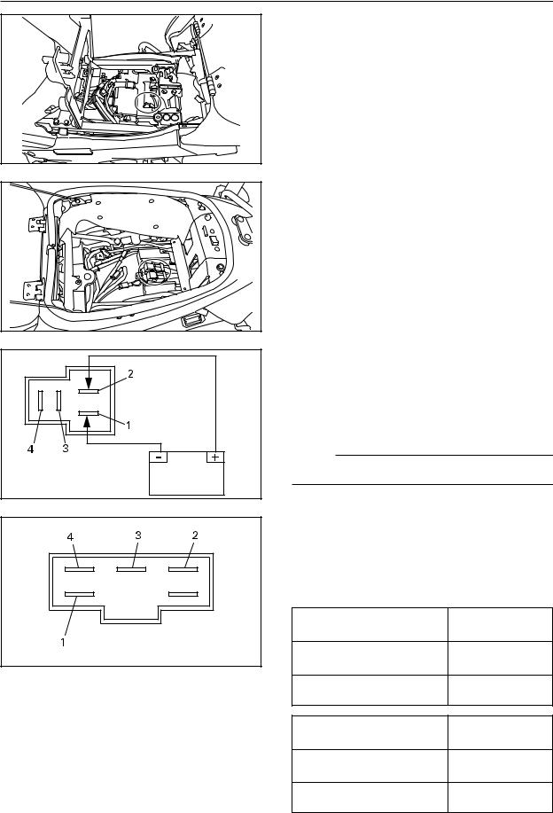
CHECKING THE RELAY
1.Disconnect the relay from the wire harness.
2.Connect the pocket tester (Ω × 1) and battery terminal (12V) to the relay terminal as shown.
No continuity between terminals 3 and 4 when battery is connected → Replace the relay.
1.Connected to the battery (+) lead
2.Connected to the battery (-) lead
3.Connected to the tester (+) lead
4.Connected to the tester (-) lead
NOTE:
Inspect the four relays by the same procedure.
CHECKING THE RECTIFIER
1.Disconnect the rectifier from the wire harness.
2.Connect the pocket tester (Ω × 1) to the rectifier terminal as shown.
Tester (+) lead → Terminal 1
Tester (-) lead → Terminal 2
Tester (+) lead → Terminal 1
Tester (-) lead → Terminal 3
Tester (+) lead → Terminal 1
Tester (-) lead → Terminal 4
Tester (+) lead → Terminal 2
Tester (-) lead → Terminal 1
Tester (+) lead → Terminal 3
Tester (-) lead → Terminal 1
Tester (+) lead → Terminal 4
Tester (-) lead → Terminal 1
Incorrect continuity → Replace the rectifier.
-16-
INTRODUCTION
Ce supplément au manuel a été rédigé en vue de proposer les nouvelles méthodes d'entretien et les nouvelles données concernant la FJR1300AP. Pour des renseignements complets relatifs aux méthodes d'entretien, il convient d'utiliser ce manuel de concert avec ceux qui suivent :
FJR1300 MANUEL DU PROPRIÉTAIRE (5P5-28199-E2, -F2, -G2, -H2, -S2) FJR1300 MANUEL D'ATELIER (3P6-28197-E2, -F2, -G2, -H2, -S2)
FJR1300AP
SUPPLEMENT AU MANUEL
POUR LE MODELE DE POLICE
2008 par la Yamaha Motor Co., Ltd. Première édition, mars 2008
Tous droits réservés Toute reproduction ou utilisation sans la permission écrite de la
Yamaha Motor Co., Ltd. est formellement interdite.

INFORMATIONS IMPORTANTES CONCERNANT LE MANUEL
Les informations particulièrement importantes sont repérées par les notations suivantes :
Le symbole de danger incite à ÊTRE VIGILANT AFIN DE GARANTIR LA SÉCURITÉ !
 AVERTISSEMENT
Le non-respect des instructions données sous un AVERTISSEMENT peut entraîner des blessures graves ou la mort du pilote, d'une personne se trouvant à proximité ou d'une personne inspectant ou réparant la moto.
ATTENTION:
La mention ATTENTION indique les précautions particulières à prendre pour éviter d'endommager la moto.
N.B.:
Un N.B. fournit les renseignements nécessaires à la clarification et la simplification des divers travaux.
N.B.:
Yamaha est sans cesse à la recherche d'améliorations dans la conception et la qualité de ses produits. Par conséquent, bien que ce manuel contienne les informations les plus récentes disponibles au moment de l'impression, il peut ne pas refléter de petites modifications apportées ultérieurement à ce modèle. Au moindre doute concernant le fonctionnement ou l'entretien du véhicule, ne pas hésiter à consulter un concessionnaire Yamaha.
TABLE DES MATIÈRES |
|
DESCRIPTION------------------------------------------------------------------------------------------------ |
1 |
CARACTÉRISTIQUES ------------------------------------------------------------------------------------- |
1 |
COMMANDES ET INSTRUMENTS --------------------------------------------------------------------- |
2 |
COMMUTATEUR DE GUIDON DROIT ------------------------------------------------------------ |
2 |
COFFRET RADIO (5P56, 5P57)--------------------------------------------------------------------- |
3 |
CHANGEMENT DU COUPLEUR POUR LES FEUX CLIGNOTANTS ARRIÉRE ------ |
4 |
RÉGLAGE DE SUSPENSION------------------------------------------------------------------------ |
4 |
ENTRETIEN --------------------------------------------------------------------------------------------------- |
5 |
COUPLE DE SERRAGE ------------------------------------------------------------------------------- |
5 |
ACHEMINEMENT DU CABLAGE ------------------------------------------------------------------- |
7 |
VERIFICATION DES COMPOSANTS ELECTRIQUES ------------------------------------- |
15 |
SCHÉMA DE CÂBLAGE |
|
DESCRIPTION / CARACTÉRISTIQUES
DESCRIPTION
 Commutateur de patrouille
 Coffret radio (5P56, 5P57)
CARACTÉRISTIQUES
Désignation du modèle |
FJR1300AP |
FJR1300AP |
FJR1300AP |
|
|
|
|
Type de modèle approuvé |
RP13 |
← |
← |
Type de modèle enregistré |
5P55 |
5P56 |
5P57 |
|
|
|
|
Longueur hors-tout (mm) |
2230 |
← |
← |
Largeur hors-tout (mm) |
740 |
← |
← |
Hauteur hors-tout (mm) |
1315 |
← |
← |
Garde au sol (mm) |
130 |
← |
← |
Poids (kg) |
264 |
← |
← |
-1-
COMMANDES ET INSTRUMENTS
COMMANDES ET
INSTRUMENTS
COMMUTATEUR DE GUIDON DROIT
 Coupe-circuit du moteur
 Commutateur de patrouille
 Contacteur du démarreur
 Contacteur des feux de détresse
COUPE-CIRCUIT DU MOTEUR
Placer ce contacteur sur " " avant de mettre le moteur en marche. En cas d'urgence, comme par exemple, lors d'une chute ou d'un blocage de câble des gaz, placer ce contacteur sur "
 " afin de couper le moteur.
COMMUTATEUR DE PATROUILLE
Ce commutateur active la sirène ou le lanternon à éclats.
N.B.:
Il sert quand une sirène ou un lanternon à éclats est installé.
DESACTIVE
Cela sert pour le lanternon à éclats.
Cela sert à la fois pour la sirène et le lanternon à éclats.
CONTACTEUR DU DÉMARREUR
Appuyer sur ce contacteur afin de lancer le moteur à l'aide du démarreur.
CONTACTEUR DES FEUX DE DÉTRESSE
Quand la clé de contact est sur "ON" ou "P", ce contacteur permet d'enclencher les feux de détresse, c.-à-d. le clignotement simultané de tous les clignotants.
Les feux de détresse s'utilisent en cas d'urgence ou pour avertir les autres automobilistes du stationnement du véhicule à un endroit pouvant représenter un danger.
ATTENTION:
Ne pas laisser les feux de détresse trop longtemps allumés lorsque le moteur est coupé, car la batterie pourrait se décharger.
-2-
COMMANDES ET INSTRUMENTS
COFFRET RADIO (5P56, 5P57)
Le couvercle peut être verrouillé en tournant la clé introduite  .
.
[a] VERROUILLE [b] OUVERT
• Le changement de position du commutateur  peut éviter de décharger la batterie.
ON : Lorsqu'on utilise un instrument auxiliaire
OFF : Lorsqu'on n'utilise pas d'instrument auxiliaire
-3-
COMMANDES ET INSTRUMENTS
CHANGEMENT DU COUPLEUR POUR
LES FEUX CLIGNOTANTS ARRIÈRE
Lorsqu'un ensemble de montants arrière (en option) est installé sur la motocyclette, ce coupleur bleu  doit être utilisé.
N.B.:
Le changement de connexion de faisceau de fils peut déterminer quel feu à allumer.
•Connexion au coupleur bleu  : Les feux clignotants arrière de l'ensemble des montants arrière latéraux s'allument.
•Connexion au coupleur blanc  : Les feux clignotants arrière du combiné de feux arrière s'allument.
RÉGLAGE DE SUSPENSION
Lorsque la motocyclette s'alourdit à cause des instruments auxiliaires installés, effectuer les réglages en se référant aux points suivants :
1.Fourche avant
• Accroître la précharge.
• Diminuer la force d'amortissement de rebond (lorsque la précharge s'accroît).
• Diminuer la force d'amortissement de compression (lorsque la précharge s'accroît).
2.Suspension arrière
•Accroître la précharge (réglage doux à réglage dur).
•Pas de changement dans la force d'amortissement de rebond.
N.B.:
Les réglages ci-dessus constituent seulement une indication générale. Ils dépendent du poids du motocycliste, etc. Il convient donc de se fier surtout à un essai de conduite.
-4-
ENTRETIEN
ENTRETIEN
COUPLE DE SERRAGE
Durant l'inspection de la motocyclette, vérifier chacune des pièces installées pour s'assurer qu'il n'y
ait pas de desserrage.
7 Nm (0.7 m • kg, 5.1 ft • lb) |
|
2 Nm (0.2 m • kg, 1.4 ft • lb) |
|
7 Nm (0.7 m • kg, 5.1 ft • lb) |
|
7 Nm (0.7 m • kg, 5.1 ft • lb) |
|
21 Nm (2.1 m • kg, 15 ft • lb) |
|
21 Nm (2.1 m • kg, 15 ft • lb) |
|
7 Nm (0.7 m • kg, 5.1 ft • lb) |
|
4 Nm (0.4 m • kg, 2.9 ft • lb) |
|
16 Nm (1.6 m • kg, 11 ft • lb) |
|
7 Nm (0.7 m • kg, 5.1 ft • lb) |
|
|
7 Nm (0.7 m • kg, 5.1 ft • lb) |
1.5 Nm (0.15 m • kg, 1.1 ft • lb) |
|
7 Nm (0.7 m • kg, 5.1 ft • lb) |
8 Nm (0.8 m • kg, 5.8 ft • lb) |
-5- |
|
 Loading...