


0-12 Daily or (pre-ride) checks
Note: The daily (pre-ride) checks outlined in the owner's manual covers those items which should be inspected on a daily basis.
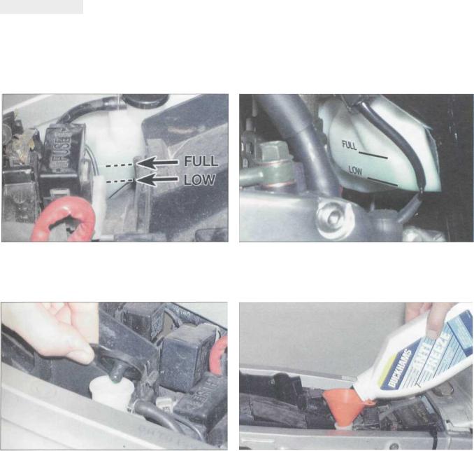
1 Engine/transmission oil level check
Before you start
•On YZF models, support the motorcycle in an upright position, using an auxiliary stand if required. On FZS models, put the motorcycle on its centrestand. Make sure it is on level ground.
•Start the engine and let it idle for several minutes to allow it to reach normal operating temperature.
Caution: Do not run the engine in an enclosed space such as a garage or workshop.
• Stop the engine. Leave the motorcycle undisturbed for a few minutes to allow the oil level to stabilise.
The correct oil
•Modern, high-revving engines place great demands on their oil. It is very important that the correct oil for your bike is used.
•Always top up with a good quality oil of the specified type and viscosity and do not overfill the engine.
Caution: Do not use chemical additives or oils with a grade of CD or higher, or use oils labelled "ENERGY CONSERVING II". Such additives or oils could cause clutch slip.
Oil type |
API grade SE, SF or SG (min) |
|
|
Oil viscosity* |
|
UK models |
SAE 10W30or10W40 |
US models |
SAE10W30or20W50 |
|
|
"Refer to the viscosity table to select the oil best suited to your conditions.
Bike care
• If you have to add oil frequently, you should check whether you have any oil leaks. If there is no sign of oil leakage from the joints and gaskets | the engine could be burning oil (see Fault Finding).
Oil viscosity table; select the oil best suited to the conditions
I Wipe the oil level inspection window, located on the right-hand side of the engine, so that it is clean.
With the motorcycle vertical, the oil level should lie between the maximum and minimum levels on the window.
3 If the level is below the minimum line, remove the filler cap from the top of the clutch cover.
4 Top the engine up with the recommended grade and type of oil, to bring the level up to the maximum level on the window.
Daily or (pre-ride) checks 0-13
2 Coolant level check
Warning: DO NOT remove the radiator pressure cap to add coolant. Topping up is done via the coolant reservoir tank filler. DO NOT leave open containers of coolant about, as it is poisonous.
Before you start
• Make sure you have a supply of coolant available - a mixture of 50% distilled water and 50% corrosion inhibited ethylene glycol anti-freeze is needed. Note: Yamaha specify that soft tap water can be used, but NOT hard water. If in doubt, boil the water first or use only distilled water.
•Always check the coolant level when the engine is cold.
•On YZF models, support the motorcycle in an upright position, using an auxiliary stand if required. On FZS models, put the motorcycle on its centrestand. Make sure it is on level ground.
Bike care
•Use only the specified coolant mixture. It is important that anti-freeze is used in the system all year round, and not just in the winter. Do not top the system up using only water, as the system will become too diluted.
•Do not overfill the reservoir. If the coolant is significantly above the "FULL" level line at any time, the surplus should be siphoned or drained off to prevent the possibility of it being expelled out of the overflow hose.
•If the coolant level falls steadily, check the system for leaks (see Chapter 1). If no leaks
are found and the level continues to fall, it is recommended that the machine is taken to a
Yamaha dealer for a pressure test.
I On YZF models, remove the seat to access the coolant reservoir
(see Chapter 8). The coolant "FULL" and "LOW" level lines are marked on the reservoir.
On FZS models, the coolant "FULL and "LOW" level lines are marked on the back of the reservoir and are visible below the right-hand side panel.
3 If the coolant level is not in between the "FULL" and "LOW" level lines, on FZS models remove the right-hand side cover (see Chapter 8, Section 3), then on all models remove the reservoir filler cap.
4 Top the coolant level up with the recommended coolant mixture. Fit the cap securely, then install the side cover (see Chapter 8).
o-i4 Daily or (pre-ride) checks
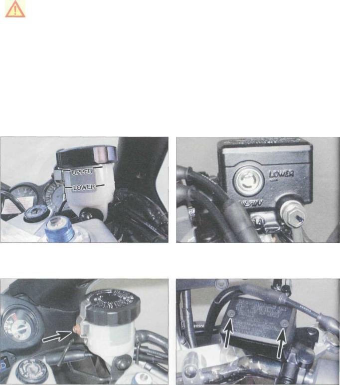
3 Brake fluid level checks
Warning: Brake hydraulic fluid can harm your eyes and damage painted surfaces, so use extreme caution when handling and pouring it and cover surrounding surfaces with rag. Do not use fluid that has been standing open for some time, as it absorbs moisture from the air which can cause a dangerous loss of braking effectiveness.
Before you start
• On YZF models, support the motorcycle in an upright position, using an auxiliary stand if required. On FZS models, put the motorcycle on its centrestand. Turn the handlebars until the top of the front master cylinder is as level as possible. If necessary, tilt the motorcycle to make it level. The rear master cylinder reservoir is located behind the right-hand side cover.
•Make sure you have the correct hydraulic fluid. DOT 4 is recommended.
•Wrap a rag around the reservoir being worked on to ensure that any spillage does not come into contact with painted surfaces.
Bike care
•The fluid in the front and rear brake master cylinder reservoirs will drop slightly as the brake pads wear down.
•If any fluid reservoir requires repeated
topping-up this is an indication of a hydraulic leak somewhere in the system, which should be investigated immediately.
•Check for signs of fluid leakage from the hydraulic hoses and components - if found rectify immediately.
•Check the operation of both brakes before taking the machine on the road; if there is evidence of air in the system (spongy feel to lever or pedal), it must be bled as described in Chapter 7.
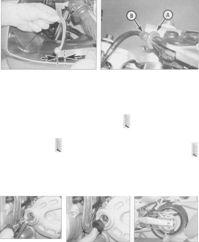
FRONT BRAKE FLUID LEVEL
I On YZF models, the front brake fluid level is visible through the reservoir body - it must be between the "UPPER" and "LOWER" level lines.
On FZS models, the front brake fluid level is visible through thJ window in the reservoir body - it must be above the "LOWER level line.
3 On YZF models, if the level is below the "LOWER" level line, remove the reservoir cap clamp screw (arrowed), then unscrew the cap and remove the diaphragm plate and the diaphragm.
On FZS models, if the level is below the "LOWER" level line remove the two reservoir cover screws (arrowed) and remove th> cover, the diaphragm plate and the diaphragm.

Daily or(pre-ride) checks 0-15
5 Top up with new clean hydraulic fluid of the recommended type, until the level is above the "LOWER" level line. Take care to avoid spills (see Warning above).
6 Ensure that the diaphragm is correctly seated before installing the plate and cover or cap. On YZF models, secure the cap with its clamp.
REAR BRAKE FLUID LEVEL
7 On YZF models, the rear brake fluid level is visible through the cutout in the righthand side cover - it must be above "LOWER"
level line.
8 On FZS models, remove the right-hand side cover (see Chapter 8, Section 3) - the rear brake fluid level is visible through the
reservoir body - it must be above "LOWER" level line.
9 If the level is below the "LOWER" level line, on YZF models remove the righthand side cover (see Chapter 8, Section 3), then slacken the reservoir cap (A) and remove the mounting screw (B), and displace the
reservoir so that it is clear of the clamp (C).
•4 A To replenish the fluid, unscrew the reservoir cap and remove the I vy diaphragm plate and diaphragm. Top up with new clean hydraulic fluid of the recommended type, until the level is above the lower mark. Take care to avoid spills (see Warning above).
1 |
H |
Ensure that the diaphragm is correctly seated before installing |
I |
the plate and cap. Tighten the cap securely. On YZF models, |
locate the reservoir and tighten its screw securely. Install the side cover (see Chapter 8).
o-i6 Daily or (pre-ride) checks
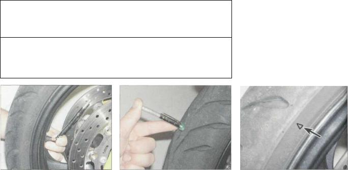
4 Tyre checks
The correct pressures
•The tyres must be checked when cold, not immediately after riding. Note that low tyre pressures may cause the tyre to slip on the rim or come off. High tyre pressures will cause abnormal tread wear and unsafe handling.
•Use an accurate pressure gauge.
•Proper air pressure will increase tyre life and provide maximum stability and ride comfort.
Tyre care
•Check the tyres carefully for cuts, tears, embedded nails or other sharp objects and excessive wear. Operation of the motorcycle with excessively worn tyres is extremely hazardous, as traction and handling are directly affected.
•Check the condition of the tyre valve and ensure the dust cap is in place.
YZF models
Loading/speed |
Front |
Rear |
Rider only |
32 psi (2.2 Bar) |
36 psi (2.5 Bar) |
Rider and passenger, or high speed riding |
36 psi (2.5 Bar) |
41 psi (2.8 Bar) |
FZS models
Loading/speed |
Front |
Rear |
Rider only |
32 psi (2.2 Bar) |
36 psi (2.5 Bar) |
Rider and passenger, or high speed riding |
32 psi (2.2 Bar) |
40 psi (2.8 Bar) |
•Pick out any stones or nails which may have become embedded in the tyre tread. If left, they will eventually penetrate through the casing and cause a puncture.
•If tyre damage is apparent, or unexplained loss of pressure is experienced, seek the advice of a tyre fitting specialist without delay.
Tyre tread depth
•At the time of writing, UK law requires that tread depth must be at least 1 mm over 3/4 ot the tread breadth all the way around the tyre, with no bald patches. Many riders, however, consider 2 mm tread depth minimum to be a safer limit. Yamaha recommend a minimum of
1.6mm.
•Many tyres now incorporate wear
indicators in the tread. Identify the triangular pointer or "TWI" mark on the tyre sidewall to locate the indicator bar and replace the tyre if the tread has worn down to the bar.
Check the tyre pressures when the tyres |
Measure tread depth at the centre of the |
Tyre tread wear indicator bar and its |
1 are cold and keep them properly inflated. |
2 tyre using a tread depth gauge. |
location marking (usually either an arrow, |
|
|
a triangle or the letters TWI) on the sidewall |
|
|
(arrowed). |
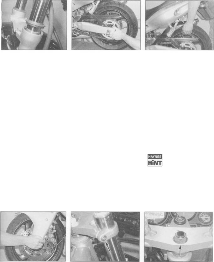
5 Suspension, steering and final drive checks |
||
Suspension and Steering |
|
Final drive |
•Check that the front and rear suspension operates smoothly without binding.
•Check that the suspension is adjusted as required.
• Check that the steering moves smoothly from lock-to-lock.
•Check that the drive chain slack isn't excessive, and adjust if necessary (see Chapter 1).
•If the chain looks dry, lubricate it (see
Chapter 1).
6 Legal and safety checks
Lighting and signalling
•Take a minute to check that the headlight, taillight, brake light, instrument lights and turn signals all work correctly.
•Check that the horn sounds when the switch is operated.
•A working speedometer graduated in mph is a statutory requirement in the UK.
Safety
•Check that the throttle grip rotates smoothly, and snaps shut when released, in all steering positions. Also check for the correct amount of freeplay (see Chapter 1).
•Check that the engine shuts off when the kill switch is operated.
•Check that sidestand and centrestand (where fitted) return springs hold the stand securely up when retracted.
Fuel
•This may seem obvious, but check that you have enough fuel to complete your journey. If you notice signs of fuel leakage - rectify the cause immediately.
•Ensure you use the correct grade fuel - see Chapter 4 Specifications.

1-1
Chapter 1
Routine maintenance and Servicing
Contents
Air filter-cleaning and replacement |
5 |
Engine oil pressure - check |
|
31 |
|||||
Battery - charging |
|
see Chapter 9 |
Front forks - oil change |
|
33 |
||||
Battery - check |
|
|
Fuel11 hoses - replacement |
|
32 |
||||
Batteryremoval, installation, inspection and |
|
Fuel system - check |
|
6 |
|||||
|
maintenance |
|
see Chapter 9 |
Headlight aim - check and adjustment |
|
29 |
|||
Brake caliper and master cylinder seals - replacement |
26 |
Idle speed - check and adjustment |
|
3 |
|||||
Brake hoses - replacement |
|
|
28Nuts and bolts - tightness check |
|
15 |
||||
Brake pads - wear check |
|
8Sidestand and centrestand (where fitted) - check |
14 |
||||||
Brake system - check |
|
9 Spark plug gaps - check and adjustment |
|
2 |
|||||
Brakes - fluid change |
|
25Stand, lever pivots and cables - lubrication |
|
18 |
|||||
Carburettor synchronisation |
|
4Steering head bearings - freeplay check and adjustment |
20 |
||||||
Clutch - check and adjustment |
|
10Steering head bearings - lubrication |
|
24 |
|||||
Cooling system - check |
|
16Suspension - check |
|
19 |
|||||
Cooling system - draining, flushing and refilling |
22 Swingarm and suspension linkage bearings - re-greasing |
23 |
|||||||
Cylinder compression - check |
|
30 Throttle and choke cables - check |
|
17 |
|||||
Drive chain and sprockets - check, adjustment and lubrication . . . . 1 |
Valve clearances - check and adjustment |
|
27 |
||||||
Engine oil and oil filter change |
|
21 Wheel bearings - check |
|
13 |
|||||
Engine oil change |
|
|
Wheels7 and tyres - general check |
|
12 |
||||
Degrees of difficulty |
|
|
|
|
|
|
|||
|
|
|
|
|
|
|
|||
|
Easy, suitable for |
|
Fairly easy, suitable |
Fairly difficult, |
Difficult, suitable for |
Very difficult, |
|
||
|
novicewith little |
|
for beginner with |
suitable for competent |
experienced DIY |
suitable for expert DIY |
|
||
|
experience |
|
some experience |
DIY mechanic |
|
mechanic |
or professional |
|
|
Specifications |
|
|
|
|
|
|
|||
Engine |
|
|
|
|
|
|
|
||
Spark plugs |
|
|
|
|
|
|
|
||
|
Type |
|
|
NGK CR9E or Nippondenso U27ESR-N |
|
|
|||
|
Electrode gap |
|
|
0.7 to 0.8 mm |
|
|
|
||
Engine idle speed |
|
|
|
|
|
|
|
||
|
YZF models |
|
|
1200 to |
1300 rpm |
|
|
||
|
FZSmodels |
|
|
1150 to 1250 rpm |
|
|
|||
Carburettorsynchronisation - intake vacuum |
|
|
|
|
|
|
|||
|
YZFmodels |
|
|
225 mmHg |
|
|
|
|
|
|
FZSmodels |
|
|
230 to 250 mmHg |
|
|
|
||
Carburettor synchronisation - max. difference between carburettors |
|
|
|
|
|
||||
|
YZF models |
|
|
10 mmHg |
|
|
|
|
|
|
FZS models |
|
|
10 mmHg |
|
|
|
|
|
Valve clearances (COLD engine) |
|
|
|
|
|
|
|||
|
Intake valves |
|
|
0.11 |
to 0.20 mm |
|
|
||
|
Exhaust valves |
|
|
0.21 to 0.30 |
mm |
|
|
||
Cylinder compression |
|
|
|
|
|
|
|
||
|
YZF models |
|
|
|
|
|
|
|
|
|
Standard |
|
|
220 psi (15.2 Bar) |
|
|
|
||
|
Maximum |
|
|
235 psi (16.2 Bar) |
|
|
|
||
|
Minimum |
|
|
185 psi (12.8 Bar) |
|
|
|
||
|
Max. difference between cylinders |
|
14.5 psi (1.0 Bar) |
|
|
|
|||
|
FZSmodels |
|
|
|
|
|
|
|
|
|
Standard |
|
|
213 psi (14.7 |
Bar) |
|
|
||
|
Maximum |
|
|
225 psi |
(15.5 |
Bar) |
|
|
|
|
Minimum |
|
|
170 psi (11.7 Bar) |
|
|
|
||
|
Max. difference between cylinders |
|
14.5 psi (1.0 Bar) |
|
|
|
|||
Engine oil pressure |
|
|
|
|
|
|
|
||
|
YZFmodels |
|
|
50 to 64 psi (3.5 to 4.4 Bar) |
|
|
|||
|
FZS models |
|
|
64 psi (4.4 Bar) |
|
|
|
||
Specifications
Miscellaneous
Drive chain slack
YZF models
FZS models 1998 and 1999 2000 models
Chain stretch limit (see text) YZF models
FZS models
Rear brake pedal height (see text) YZF models
FZS models Clutch cable freeplay
Throttle cable freeplay YZF models
FZS models
Tyre pressures (cold)
Recommended lubricants and fluids
Engine/transmission oil type
Engine/transmission oil capacity
YZF models Oil change
Oil and filter change
Following engine overhaul - dry engine, new filter
FZS models Oil change
Oil and filter change
Following engine overhaul - dry engine, new filter Coolant type
Coolant capacity
Brake fluid
Drive chain
Miscellaneous
Steering head bearings Swingarm pivot and bearings Suspension linkage bearings
Bearing seal lips
Gearchange lever/clutch lever/front brake lever/ rear brake pedal/sidestand/centrestand pivots
Cables Throttle grip
Torque settings
Alternator cover bolts Cooling system drain plug(s)
Fork clamp bolts (top yoke) Main oil gallery plug
Oil drain plug
Oil filter
Rear axle nut
Spark plugs YZF models FZS models
Steering head bearing adjuster nut (using Yamaha service tool) YZF models
Initial setting
Final setting FZS models
Initial setting
Final setting Steering stem nut
20 to 30 mm
30 to 40 mm
30 to 45 mm
151mm 150 mm
42 mm
36.6 mm
10 to 15 mm at lever end
3 to 7 mm
3 to 5 mm
see Daily (pre-ride) checks
see Daily (pre-ride) checks
2.6litres
2.9litres
3.5litres
2.5litres
2.7litres
3.5litres
50% corrosion inhibited ethylene glycol anti-freeze, 50% distilled water. Note: Yamaha specify that soft tap water can be used, but NOT hard water. If in doubt, boil the water first or use only distilled water.
1.95 litres DOT 4
SAE 30 to 50 W engine oil or chain lubricant suitable for O-ring chains
Lithium-based multi-purpose grease
Molybdenum disulphide grease
Molybdenum disulphide grease
Lithium-based multi-purpose grease
Lithium-based multi-purpose grease 10W30 motor oil
Multi-purpose grease or dry film lubricant
12 Mm
10 Nm
30 Nm
8 Nm
43 Nm
17 Nm
117Nm
12.5Nm
13Nm
52 Nm
3 Nm
52 Nm
18Nm
110 Nm

Maintenance schedule K
Note: The daily (pre-ride) checks outlined in the owner's manual covers those items which should be inspected on a daily basis. Always perform the pre-ride inspection at every
maintenance interval (in addition to the procedures listed). The intervals listed below are the intervals recommended by the manufacturer for each particular operation
during the model years covered in this manual. Your owner's manual may have different intervals for your model.
Daily (pre-ride)
See 'Daily (pre-ride) checks' at the beginning of this manual.
After the initial 600 miles (1000 km)
Note: This check is usually performed by a Yamaha dealer after the first 600 miles (1000 km) from new. Thereafter, maintenance is carried out according to the following intervals of the schedule.
Every 600 miles (1000 km)
D Check, adjust, clean and lubricate the drive chain (Section 1)
Every 4000 miles (6000 km) or 6months(whichevercomessooner)
H Check the spark plug gaps (Section 2)
I] Check and adjust the idle speed (Section 3) D Check/adjust the carburettor synchronisation
(Section 4)
D Clean and check the air filter element (Section 5) I Check the fuel system and hoses (Section 6)
D Change the engine oil (Section 7) j Check the brake pads (Section 8)
L Check the brake system and brake light switch operation (Section 9)
D Check and adjust the clutch (Section 10) C Check the battery (Section 11)
M Check the condition of the wheels and tyres (Section 12)
H Check the wheel bearings (Section 13)
C Check the sidestand and centrestand (where fitted) (Section 14)
I! Check the tightness of all nuts, bolts and fasteners (Section 15)
Check the cooling system (Section 16)
nCheck and adjust the throttle and choke cables (Section 17)
3 Lubricate the clutch/gearshift/brake lever/brake pedal/sidestand/centrestand pivots and the throttle/choke/clutch cables (Section 18)
^ Check the suspension (Section 19)
H Check and adjust the steering head bearings (Section 20)
Every 8000 miles (12,000 km) or
12 months (whichevercomes sooner)
Carry out all the items under the 4000 mile (6000 km) check, plus the following
D Change the engine oil and filter (Section 21)
D Replace the spark plugs (US models) (Section 12)
Every 16,000 miles (24,000 km) or two years (whichever comes sooner)
Carry out all the items under the 8000 mile (12000 km) check, plus the following
D Replace the coolant (Section 22)
D Re-grease the swingarm and suspension linkage bearings (Section 23).
D Re-grease the steering head bearings (Section 24). D Change the brake fluid (see Section 25)
nReplace the brake master cylinder and caliper seals (Section 26)
Every 28,000 miles (42,000 km) or 42 months (whichever comes sooner)
Carry out all the items under the 4000 mile (6000 km) check, plus the following
D Check and adjust the valve clearances (Section 27)
Every four years
D Replace the brake hoses (Section 28)
Non-scheduled maintenance
D Check and adjust the headlight aim (Section 29) D Check the cylinder compression (Section 30) D Check the engine oil pressure (see Section 31) n Replace the fuel hoses (Section 32)
D Change the front fork oil (Section 33)
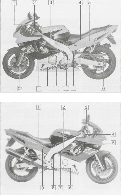
1-4 Component location - YZF600R Thundercat
Component locations on left-hand side
1 Clutch cable adjuster
2 Steering head bearings
3 Air filter housing
4 Model code label
5 Fuse box
6 Drive chain adjuster
7 Rear suspension pre-load adjuster
8 Coolant drain plug
9 Engine oil drain plug
10 Carburettor vent hose
11 Engine oil filter
12 Speedometer cable
11 10 9 87
Component locations on right-hand side
1 Coolant reservoir
2 Idle speed adjuster
3 Front brake fluid reservoir
4 Frame number
5 Cooling system pressure cap
6 Engine oil level inspection window
7 Engine number
8 Engine oil filler plug
9 Rear brake fluid reservoir
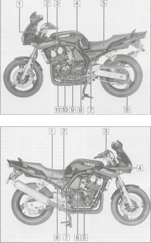
Component location - FZS600 Fazer 1-5
Component locations on left-hand side
1 Steering head bearings
2Clutch cable adjuster
3Cooling system pressure cap
4Air filter housing
5Model code label
6Drive chain adjuster
7 Rear suspension pre-load adjuster
8Coolant drain plug
9Idle speed adjuster 10 Engine oil drain plug
11Engine oil filter
Component locations on right-hand side
1 Fuse box
2Coolant reservoir
3Front brake fluid reservoir
4Frame number
5Engine oil level inspection window
6Engine number
7 Engine oil filler plug
8 Rear brake fluid reservoir
•6 Maintenance procedures
Introduction
1 This Chapter is designed to help the home mechanic maintain his/her motorcycle for safety, economy, long life and peak performance.
2 Deciding where to start or plug into the routine maintenance schedule depends on several factors. If the warranty period on your motorcycle has just expired, and if it has been maintained according to the warranty standards, you may want to pick up routine maintenance as it coincides with the next mileage or calendar interval. If you have owned the machine for some time but have
never performed any maintenance on it, then you may want to start at the nearest interval and include some additional procedures to ensure that nothing important is overlooked. If you have just had a major engine overhaul, then you may want to start the maintenance routine from the beginning. If you have a used machine and have no knowledge of its history or maintenance record, you may desire to combine all the checks into one large service initially and then settle into the maintenance schedule prescribed.
3 Before beginning any maintenance or
repair, the machine should be cleanec thoroughly, especially around the oil filter spark plugs, valve cover, side panels carburettors, etc. Cleaning will help ensure that dirt does not contaminate the engine anc will allow you to detect wear and damage thai could otherwise easily go unnoticed.
4 Certain maintenance information i; sometimes printed on decals attached to the motorcycle. If the information on the decal; differs from that included here, use the information on the decal.
Every 600 miles (1000 km)
1 Drive chain and sprockets - |
|
check, adjustment and |
^ |
lubrication |
2^ |
Check
1 A neglected drive chain won't last long and can quickly damage the sprockets. Routine chain adjustment and lubrication isn't difficult and will ensure maximum chain and sprocket life.
1.3 Push up on the chain and measure the slack
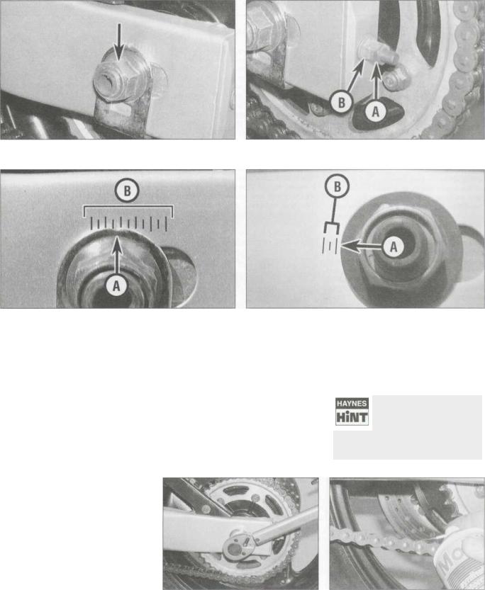
2 To check the chain, place the bike on its sidestand and shift the transmission into neutral.
3 Push up on the bottom run of the chain and measure the slack midway between the two sprockets, then compare your measurement to that listed in this Chapter's Specifications (see illustration). As the chain stretches with wear, adjustment will periodically be necessary (see below). Since the chain will rarely wear evenly, roll the bike forwards so that another section of chain can be checked; do this several times to check the entire length of chain.
4 Check the amount of chain stretch by measuring a 10-link section of clean chain as shown and comparing the length to the
Specifications (see illustration). Repeat the test at 2 or 3 other places on the chain. If the chain has stretched beyond the limit, replace it with a new one (see Chapter 6).
5 In some cases where lubrication has been neglected, corrosion and galling may cause the links to bind and kink, which effectively shortens the chain's length. Such links should be thoroughly cleaned and worked free. If the chain is tight between the sprockets, rusty or kinked, it's time to replace it with a new one. If
you find a tight area, mark it with felt pen oi paint, and repeat the measurement after the bike has been ridden. If the chain's still tight ir the same area, it may be damaged or worn
Because a tight or kinked chain can damage the transmission output shaft bearing, it's i good idea to replace it with a new one (see Chapter 6).
6 Check the entire length of the chain fo damaged rollers, loose links and pins, anc missing O-rings and replace it if damage is found. Note: Never install a new chain on ok sprockets, and never use the old chain if yot install new sprockets - renew the chain anc sprockets as a set.
7 Remove the front sprocket cover (sef Chapter 6). Check the teeth on the engin! sprocket and the rear wheel sprocket for wea
(see illustration).
8 Inspect the drive chain slider on thi swingarm for excessive wear and renew it i worn (see Chapter 6).
Adjustment
9 Rotate the rear wheel until the chain ii positioned with the tightest point at the centri of its bottom run, then place the machine oi its sidestand.
DIRECTION OF ROTATION
OHO 0)(0 OHO 0)(0 O
ENGINE SPROCKET |
REAR SPROCKET |
WORN TOOTH |
WORN TOOTH |
|
061SH |
1.4 Check the amount of stretch by measuring a 10-link length as shown
1.7 Check the sprockets in the areas indicated to see if they are worn excessively
Every 600 miles (1000 km)
1.10 Slacken the rear axle nut (arrowed) |
1.11 a Slacken the locknut (A) and turn the adjuster (B) as required |
1.11b On YZF models, check the relative position of the notch (A) |
1.11 c On FZS models, check the relative position of the washer |
with the lines (B) on each side |
(A) with the lines (B) on each side |
10Slacken the axle nut (see illustration).
11Slacken the adjuster locknut on each side of the swingarm, then turn the adjusters evenly until the amount of freeplay specified at the beginning of the Chapter is obtained at the centre of the bottom run of the chain (see illustration). Following chain adjustment, check that each chain adjustment marker is in the same position in relation to the marks on the swingarm (see illustrations). It is important each adjuster aligns with the same notch; if not, the rear wheel will be out of alignment with the front. Also check that there is no clearance between the adjuster and the end of the swingarm - push the wheel forwards to eliminate any.
12If there is a discrepancy in the chain adjuster positions, adjust one of them so that its position is exactly the same as the other. Check the chain freeplay as described above and readjust if necessary.
13Tighten the axle nut to the torque setting specified at the beginning of the Chapter, then tighten the adjuster locknuts securely (see illustration).
Lubrication
14 If required, wash the chain in paraffin
(kerosene), then wipe it off and allow it to dry, using compressed air if available. If the chain is excessively dirty it should be removed from
the machine and allowed to soak in the paraffin (see Chapter 6).
Caution: Don't use petrol, solvent or other cleaning fluids which might damage the internal sealing properties of the chain. Don't use high-pressure water. The entire process shouldn't take longer than ten minutes - if it does, the O-rings in the chain rollers could be damaged.
15 For routine lubrication, the best time to lubricate the chain is after the motorcycle has been ridden. When the chain is warm, the lubricant will penetrate the joints between the side plates better than when cold. Note:
Yamaha specifies SAE 30 to 50 W engine oil;
1.13 Tighten the axle nut to the specified torque
do not use chain lube, which may contain solvents that could damage the O-rings, unless it is specified for O-ring chains. Apply the lubricant to the area where the side plates overlap - not the middle of the rollers (see illustration).
Apply the lubricant to the top of the lower chain run, so centrifugal force will work it into the chain when the
bike is moving. After applying the lubricant, let it soak in a few minutes before wiping off any excess.
1.15 Apply the lubricant to the overlap between the sideplates

•8 Maintenance procedures
Every 4000 miles (6000 km) or 6 months
2Spark plug gaps - check and adjustment
1Make sure your spark plug socket is the correct size before attempting to remove the plugs - a suitable one is supplied in the motorcycle's tool kit which is stored under the seat.
2Using compressed air if available, clean the area around the base of the spark plugs to prevent any dirt falling into the engine when the plugs are removed.
3Check that the cylinder location is marked
on each plug lead, then pull the spark plug cap off each spark plug (see illustration). Using either the plug removing tool supplied in the bike's toolkit or a deep socket type wrench, unscrew the plugs from the cylinder head (see illustration). Lay each plug out in relation to its cylinder; if any plug shows up a problem it will then be easy to identify the troublesome cylinder.
4 Inspect the electrodes for wear. Both the centre and side electrodes should have square edges and the side electrodes should be of uniform thickness. Look for excessive deposits and evidence of a cracked or chipped insulator around the centre electrode. Compare your spark plugs to the colour spark plug reading chart at the end of this manual.
Check the threads, the washer and the ceramic insulator body for cracks and other damage.
5If the electrodes are not excessively worn, and if the deposits can be easily removed with a wire brush, the plugs can be re-gapped and re-used (if no cracks or chips are visible in the insulator). If in doubt concerning the condition of the plugs, replace them with new ones, as the expense is minimal. On UK models, Yamaha do not specify a replacement interval, but leave it to the discretion of the owner. On US models, Yamaha specify that the spark plugs should be renewed at every second service interval.
6Cleaning spark plugs by sandblasting is
permitted, provided you clean the plugs with a high flash-point solvent afterwards.
7Before installing the plugs, make sure they are the correct type and heat range and check the gap between the electrodes (see illustrations). Compare the gap to that specified and adjust as necessary. If the gap must be adjusted, bend the side electrodes only and be very careful not to chip or crack the insulator nose (see illustration). Make sure the washer is in place on the plug before installing it.
8Since the cylinder head is made of aluminium, which is soft and easily damaged, thread the plugs into the heads turning the
tool by hand (see illustration). Once the
plugs are finger-tight, the job can be finished with a spanner on the tool supplied or a socket drive (see illustration 2.3b). If a torque wrench can be applied, tighten the spark plugs to the specified torque setting. Otherwise tighten them according the instructions on the box, or by 1/4 to 1/2 turn ; after they have been fully hand tightened and have seated. Do not over-tighten them.
As the plugs are quite
,, recessed, you can slip a
HllUT short length of hose over the end of the plug to use as a tool to thread it into place. The hose will
grip the plug well enough to turn it, but will start to slip if the plug begins to cross-thread in the hole - this will prevent damaged threads.
9 Reconnect the spark plug caps, making sure they are securely connected to the correct cylinder. Install all other components previously removed.
|
Stripped plug threads in the |
9 |
I cylinder head can be |
HllUT repaired with a Heli-Coil insert - see Tools and Workshop Tips' in the Reference
section.
-am
It
J
2.3a Remove the spark plug cap , |
2.3b ... then unscrew the spark plug |
2.7a Using a wire type gauge to measure |
|
|
the spark plug electrode gap |
A
2.7b Using a feeler gauge to measure the spark plug electrode gap
2.7c Adjust the electrode gap by bending the side electrode only
2.8Thread the plug as far as possible turning the tool by hand
Every 4000 miles (6000 km) or 6 months 1-9
3.3a Idle speed adjuster screw (arrowed) - |
3.3b Idle speed adjuster screw (arrowed) • |
YZF models |
FZS models |
3 Idle speed - |
1 |
4 Carburettor synchronisation |
check and adjustment |
|
|
|
I |
|
1 The idle speed should be checked and adjusted before and after the carburettors are synchronised (balanced) and when it is obviously too high or too low. Before adjusting the idle speed, make sure the valve clearances and spark plug gaps are correct, and the air filter is clean. Also, turn the handlebars back-and-forth and see if the idle speed changes as this is done. If it does, the throttle cable may not be adjusted or routed correctly, or may be worn out. This is a dangerous condition that can cause loss of control of the bike. Be sure to correct this problem before proceeding.
2 The engine should be at normal operating temperature, which is usually reached after 10 to 15 minutes of stop-and-go riding. Make sure the transmission is in neutral, and place the motorcycle on its stand.
3 The idle speed adjuster is located on the right-hand side of the engine on YZF models, and on the left-hand side on FZS models (see illustrations). With the engine idling, adjust the idle speed by turning the adjuster screw until the idle speed listed in this Chapter's
Specifications is obtained. Turn the screw clockwise to increase idle speed, and anticlockwise to decrease it.
4 Snap the throttle open and shut a few times, then recheck the idle speed. If necessary, repeat the adjustment procedure. 5 If a smooth, steady idle can't be achieved, the fuel/air mixture may be incorrect (check the pilot screw settings - see Chapter 4,
Section 5) or the carburettors may need synchronising (see Section 4). Also check the intake manifold rubbers for cracks which will cause an air leak, resulting in a weak mixture.
Warning: Petrol (gasoline) is extremely flammable, so take extra precautions when you work
on any part of the fuel system. Don't smoke or allow open flames or bare light bulbs near the work area, and don't work in a garage where a natural gas-type appliance is present. If you spill any fuel on your skin, rinse it off immediately with soap and water. When you perform any kind of work on the fuel system, wear safety glasses and have a fire extinguisher suitable for a Class B type fire (flammable liquids) on hand.
Warning: Take great care not to A burn your hand on the hot engine unit when accessing the gauge take-off points on the intake manifolds. Do
not allow exhaust gases to build up in the work area; either perform the check outside or use an exhaust gas extraction system.
1 Carburettor synchronisation is simply the process of adjusting the carburettors so they pass the same amount of fuel/air mixture to each cylinder. This is done by measuring the
4.4a Detach the hoses from their clips (A), then remove the blanking plugs (B)
vacuum produced in each cylinder. Carburettors that are out of synchronisation will result in decreased fuel mileage, increased engine temperature, less than ideal throttle response and higher vibration levels.
Before synchronising the carburettors, make sure the valve clearances and idle speed are properly set.
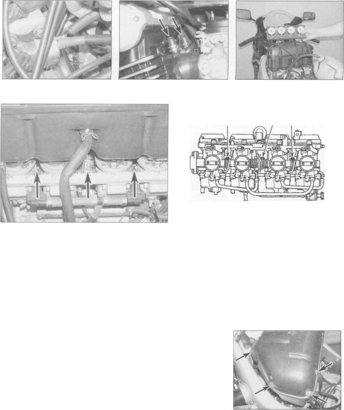
2 To properly synchronise the carburettors you will need a set of vacuum gauges or a manometer. These instruments measure engine vacuum, and can be obtained from motorcycle dealers or mail order parts suppliers. The equipment used should be suitable for a four cylinder engine and come complete with the necessary adapters and hoses to fit the take off points. Note: Because of the nature of the synchronisation procedure and the need for special instruments, most owners leave the task to a Yamaha dealer.
3Start the engine and let it run until it reaches normal operating temperature, then shut it off.
4On YZF models, remove the fuel tank (see
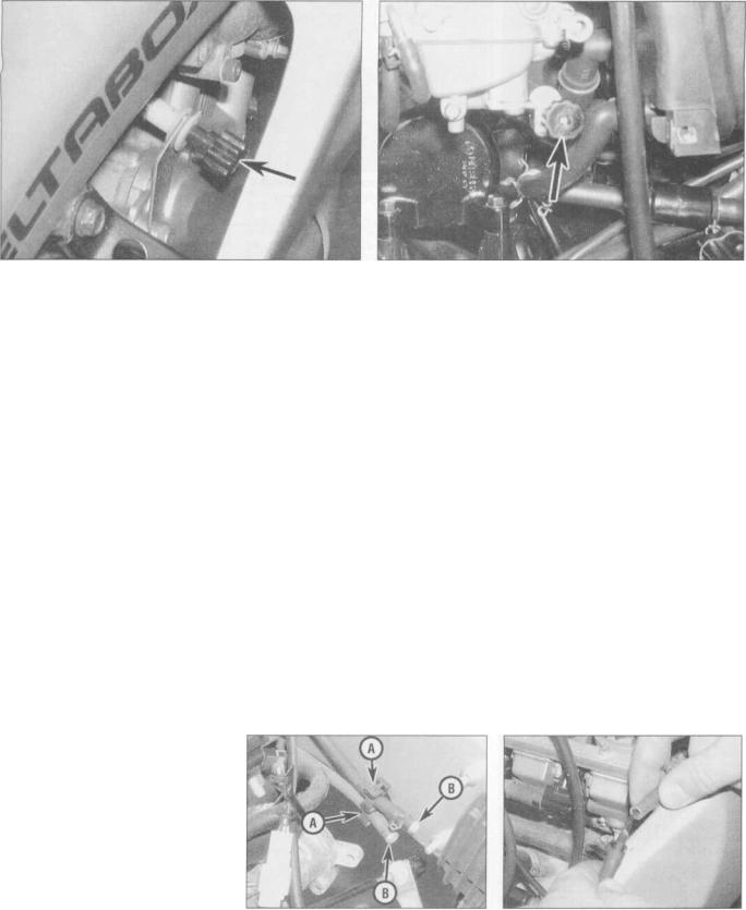
Chapter 4). Detach the vacuum hoses from their clips on each frame beam (there are two hoses on each side), then pull the blanking plug out of the end of each hose in turn and attach the gauge or manometer hoses to them using a suitable union (see illustrations).
4.4b Connect the gauge hoses using suitable unions
Every 4000 miles (6000 km) or 6 months
4.4c Connect the remote fuel supply to the fuel pump union
4.5 Remove the blanking cap (arrowed) |
4.7 Carburettor sychronisation set-up |
from each intake manifold |
|
4.8a Carburettor synchronisation screws (arrowed) - |
4.8b Carburettor synchronisation screws (arrowed) • |
YZF models |
FZS models |
On California models, only three of the hoses will have blanking plugs, while the other one will be attached to a union on one of the EVAP system components. Make sure the No. 1 gauge is attached to the hose from the No. 1
(left-hand) carburettor, and so on. Arrange a temporary fuel supply, either by using a small temporary tank with its hose attached to the fuel pump (see illustration), or by using an extra long fuel pipe to the now remote fuel tank. Alternatively, position the tank on a suitable base on the motorcycle, taking care not to scratch any paintwork, and making sure that the tank is safely and securely supported, and that access to the synchronising screws is not restricted.
5On FZS models, remove the blanking plugs from the take-off stubs on the intake manifolds between each carburettor and the cylinder head and attach the gauge or manometer hoses to them using a suitable union (see illustration). Make sure the No. 1 gauge is attached to the hose from the No. 1 (left-hand) carburettor, and so on.
6Start the engine and let it idle. If the gauges are fitted with damping adjustment, set this so that the needle flutter is just eliminated but so that they can still respond to small changes in pressure.
7 The vacuum readings for all cylinders should be the same (see illustration). If the vacuum readings differ, proceed as follows.
8 The carburettors are balanced by turning the synchronising screws situated in-between each carburettor, in the throttle linkage (see illustrations). Note: Do not press on the screws whilst adjusting them, otherwise a false reading will be obtained. First synchronise No. 1 carburettor to No. 2 using the left-hand synchronising screw until the readings are the same. Then synchronise No. 3 carburettor to No. 4 using the right-hand screw. Finally synchronise Nos. 1 and 2 carburettors to Nos. 3 and 4 using the centre screw. When all the carburettors are synchronised, open and close the throttle quickly to settle the linkage, and recheck the gauge readings, readjusting if necessary.
9 When the adjustment is complete, recheck the vacuum readings, then adjust the idle speed (see Section 3) until the speed listed in this
Chapter's Specifications is obtained. Remove the gauges and refit the blanking plugs or caps as required by your model (see Steps 4 and 5). On California models, do not forget to attach the vacuum hose to the EVAP system. On YZF models, detach the temporary fuel supply and install the fuel tank (see Chapter 4).
5 Air filter- |
I |
cleaning and replacement |
|
|
I |
1Remove the fuel tank (see Chapter 4). On
FZS models, remove the rubber trim cover, which is secured by two lugs.
2Remove the screws securing the air filter cover to the filter housing, then remove the cover and withdraw the filter element from the housing (see illustrations).
5.2a On YZF models, remove the four screws on each side (arrowed) and lift off the cover..
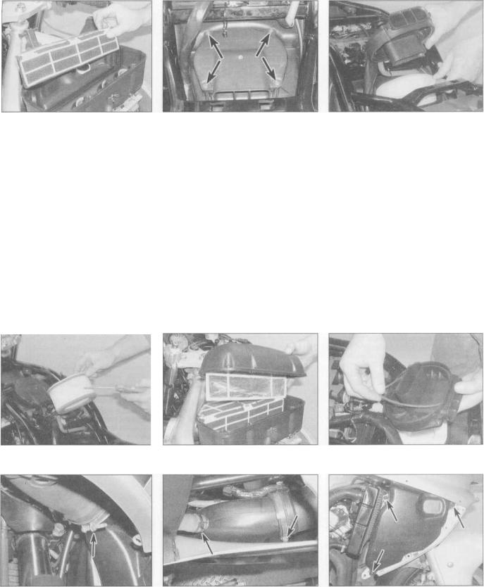
Every 4000 miles (6000 km) or 6 months 1-11
5.2b . . . then withdraw the element
3 On YZF models, clean the element using a high flash-point solvent, then remove the solvent by patting the element dry. If available, use compressed air to dry the element. Smear the entire surface of the element with clean engine oil and allow it to soak in. Again pat the element to soak up any excess oil - the element should be wet with oil but none should be dripping off it.
4 On FZS models, tap the element on a hard surface to dislodge any large particles of dirt, then if compressed air is available, use it to clean the element, directing the air from the outside in (see illustration).
5 Check the element for signs of damage. If the element is torn or cannot be cleaned, or is obviously beyond further use, replace it with a newone.
6 Install the filter element, making sure it is
5.2c On FZS models, remove the screws
(arrowed) and lift off the cover ...
properly seated - on YZF models the element fits into the large slots in the housing (see illustration 5.2b). Fit the air filter cover, making sure the rubber seal is in place, and on YZF models making sure the gauze screen fits into the small slots behind the filter element (see illustrations). On FZS models, fit the rubber trim cover. Install the fuel tank
(see Chapter 4).
7 Check that the collector in the air filter housing drain hose has not become blocked, and drain it if necessary - on YZF models the hose comes out of the rear left side of the housing, and on FZS it comes out of the front left side of the housing.
8 Check the crankcase breather hose between the engine and the air filter housing for loose connections, cracks and deterioration and replace it with a new one if necessary.
5.2d ... then withdraw the element
9 On YZF models, the surge tanks in the air intake system must also be drained and cleaned. Remove the fairing side panels to access them (see Chapter 8, Section 3). Release the clamps securing each tank to the intake in the fairing, to the air duct, to the filter housing, and to the hose on the top (see illustrations). Access to the front clamp screws is best achieved by turning the handlebars onto full lock. Remove the screws securing each tank and remove the tanks, noting how they fit. Flush the tanks out with clean water then allow them to drain. Repeat until all debris is removed, then allow them to dry before refitting them.
Caution: If the machine is continually ridden in dusty conditions, the filter should be cleaned more frequently.
5.4 Clean the element using compressed |
5.6a Installing the cover on YZF models |
5.6b Make sure the rubber seal is in place |
air if available |
|
- FZS shown |
5.9a Slacken the front clamp (arrowed)... |
5.9b |
. . . and the rear clamps (arrowed) |
5.9c . .. |
then remove the screws (arrowed) |
|
|
and detach the top hose ... |
|
and detach the surge tank |
Every 4000 miles (6000 km) or 6 months
6.5 On YZF models, drain the carburettor vent hose collector (arrowed)
Fuel system - check
Warning: Petrol (gasoline) is extremely flammable, so take extra precautions when you work on any part of the fuel system. Don't smoke or
allow open flames or bare light bulbs near the work area, and don't work in a garage where a natural gas-type appliance is present. If you spill any fuel on your skin, rinse it off immediately with soap and water. When you perform any kind of work on the fuel system, wear safety glasses and have a fire extinguisher suitable for a Class B type fire (flammable liquids) on hand.
Check
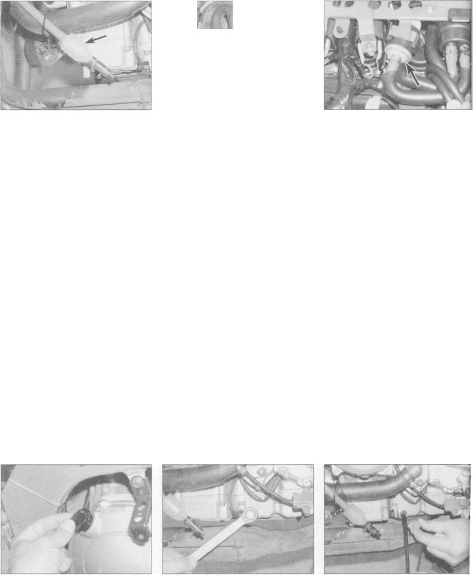
1Remove the fuel tank (see Chapter 4) and check the tank, the fuel tap, the filter, the fuel pump and the fuel hoses for signs of leakage, deterioration or damage; in particular check that there is no leakage from the fuel hoses. Replace any hoses which are cracked or deteriorated.
2If the fuel tap is leaking, tighten the assembly screws and mounting bolts (see Chapter 4). If leakage persists remove the tap and disassemble it, noting how the components fit. Inspect all components and replace any that are worn or damaged. Some components are available individually, though it may be necessary to replace the whole tap,
depending on the fault.
3 If the carburettor gaskets are leaking, the carburettors should be disassembled and rebuilt
6.8a In-line fuel filter (arrowed) - YZFmodels
using new gaskets and seals (see Chapter 4).
4 On California models, check the EVAP system hoses for loose connections, cracks and deterioration and replace them with new ones if necessary.
5 On YZF models, remove the left-hand fairing side panel (see Chapter 8, Section 3), then remove the plug from the end of the carburettor vent hose on the left-hand side of the engine and allow any residue that has accumulated in the collector to completely drain (see illustration). Install the plug on completion.
Filter cleaning
6 Replacement of the fuel filter is advised after a particularly high mileage has been covered. It is also necessary if fuel starvation is suspected.
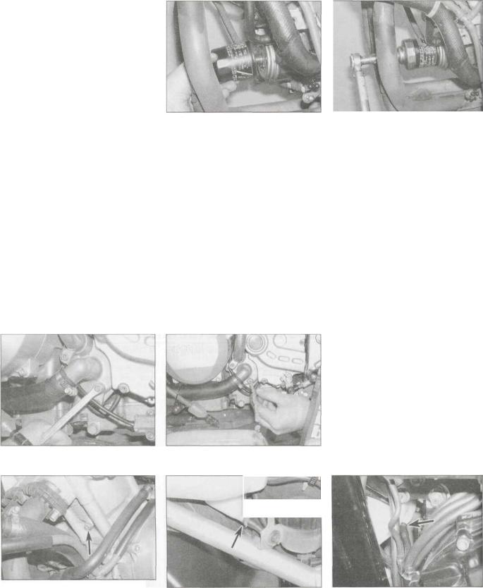
7A fuel strainer is mounted in the tank and is integral with the fuel tap. Remove the fuel tank and the fuel tap (see Chapter 4). Clean the gauze strainer to remove all traces of dirt and fuel sediment. Check the gauze for holes. If any are found, a new tap should be fitted - the strainer is not available separately.
8An in-line fuel filter is fitted in the hose from the fuel tap to the fuel pump - on YZF models, it is on the underside of the fuel tank, on FZS models it is next to the fuel pump (see illustrations). Remove the fuel tank for
access (see Chapter 4). If the filter is dirty or clogged or otherwise needs replacing, have a rag handy to soak up any residual fuel, then release the clamps and disconnect the hoses from the filter. Release the filter from its holder and install the new filter so that its arrow
6.8b In-line fuel filter (arrowed) - FZS models
points in the direction of fuel flow (i.e. towards! the pump). Fit the hoses to unions on the filter! and secure them with the clamps. Install the! fuel tank (see Chapter 4). Start the engine and! check that there are no leaks.
7 Engine oil change
:
Warning: Be careful whenl draining the oil, as the exhaust! pipes, the engine, and the oil itsen can cause severe burns.
1Consistent routine oil and filter changes arel the single most important maintenance pro-J cedure you can perform on a motorcycle. The! oil not only lubricates the internal parts of thj engine, transmission and clutch, but it alsJ acts as a coolant, a cleaner, a sealant, and a protectant. Because of these demands, the oil takes a terrific amount of abuse and should bel replaced often with new oil of the recomJ mended grade and type. The oil filter should be changed with every second oil change.
2Before changing the oil, warm up the engine so the oil will drain easily. On YZF models, remove the left-hand fairing side panel (see Chapter 8, Section 3).
3Put the motorcycle on its sidestand, and position a clean drain tray below the engine. Unscrew the oil filler cap from the clutch covei to vent it and to act as a reminder that there is no oil in the engine (see illustration).
4Unscrew the oil drain plug from the left-
hand side of the crankcase and allow the oil to flow into the drain tray (see illustrations).
7.3 Remove the oil filler cap from the clutch cover
7.4a Unscrew the crankcase oil drain |
7.4b ... |
and allow the oil to drain |
plug ... |
|
|

Every 4000 miles (6000 km) or 6 months 1-13
7.4c To remove the old sealing washer, cut it off
Check the condition of the sealing washer on the drain plug and discard it if it is damaged or worn - it will probably be necessary to cut the old one off using cutters (see illustration).
5 When the oil has completely drained, fit the plug into the crankcase, using a new sealing washer if required, and tighten it to the torque setting specified at the beginning of the
Chapter (see illustrations). Avoid overtightening, as damage to the crankcase will result.
6 Refill the engine to the proper level using the recommended type and amount of oil (see
Daily (pre-ride) checks). With the motorcycle vertical, the oil level should lie between the maximum and minimum level lines on the inspection window (see Daily (pre-ride) checks). Install the filler cap. Start the engine and let it run for two or three minutes. Stop the engine, wait a few minutes, then check the oil level. If necessary, add more oil to bring the level up to the maximum level line on the window. Check around the drain plug for leaks.
UTOJI35 Saving a little money on the VUUISl (jifference between good
\IM mU^f\
HINT and cheap oils won't pay off if the engine is damaged as a result.
7 Every so often, and especially as Yamaha do not fit an oil pressure switch and warning light (the system fitted uses an oil level sensor), it is advisable to perform an oil pressure check (see Section 31).
7.5a Install the drain plug, using a new
sealing washer if necessary ...
8 The old oil drained from the engine cannot be re-used and should be disposed of properly. Check with your local refuse disposal company, disposal facility or environmental agency to see whether they will accept the used oil for recycling. Don't pour used oil into drains or onto the ground.
:
7.5b ... and tighten it to the specified torque
measure the amount of friction material remaining - the minimum is 0.5 mm.
4 Refer to Chapter 7 for details of pad replacement.
9Brake system - check
|
|
|
Check the old oil carefully - |
|
|
||||
|
HilUT |
if it is very metallic coloured, |
|
|
|||||
|
then |
the |
engine |
is |
|
1 A routine general check of the brake system |
|||
|
|
|
experiencing |
wear |
from |
|
will ensure that any problems are discovered |
||
|
break-in (new engine) or from |
|
and remedied before the rider's safety is |
||||||
|
insufficient |
lubrication. |
If there |
are |
|
jeopardised. |
|||
|
flakes or chips of metal in the oil, then |
|
2 Check the brake lever and pedal for |
||||||
|
something |
is |
drastically wrong |
|
looseness, improper or rough action, |
||||
|
internally and the engine will have to be |
|
excessive play, bends, and other damage. |
||||||
|
disassembled for inspection and repair. |
|
Replace any damaged parts with new ones |
||||||
|
If there are pieces of fibre-like material |
|
(see Chapter 7). Clean and lubricate the lever |
||||||
|
in the oil, the clutch is experiencing |
|
and pedal pivots if their action is stiff or rough |
||||||
|
excessive wear and should be checked. |
|
(see Section 18). |
||||||
|
|
|
|
|
|
|
|
|
3 Make sure all brake fasteners are tight. |
9 On YZF models, install the left-hand fairing |
Check the brake pads for wear (see Section 8) |
||||||||
side panel (see Chapter 8). |
|
|
|
and make sure the fluid level in the reservoirs |
|||||
|
|
|
|
|
|
|
|
|
is correct (see Daily (pre-ride) checks). Look |
|
|
|
|
|
|
|
|
|
for leaks at the hose connections and check |
|
|
|
|
|
|
|
|
|
for cracks in the hoses themselves (see |
|
|
Brake pads - |
|
|
|
|
|||
|
|
|
|
|
|
illustration). If the lever or pedal is spongy, |
|||
|
|
wear check |
|
|
|
|
|||
|
|
|
|
I |
|||||
|
|
|
|
|
|
|
|
|
bleed the brakes (see Chapter 7). |
|
|
|
|
|
|
|
I4 Make sure the brake light operates when the |
||
front brake lever is pulled in. The front brake light switch, mounted on the underside of the master cylinder, is not adjustable. If it fails to operate properly, check it (see Chapter 9).
5 Make sure the brake light is activated just before the rear brake takes effect. If adjustment is necessary, hold the switch and turn the
8.2 Brake pad wear indicator (arrowed) - |
9.3 Flex the brake hose and check for |
YZF shown |
cracks, bulges and leaking fluid |
Every 4000 miles (6000 km) or 6 months
9.5 Rear brake light switch (arrowed) - |
9.6 Front brake lever span adjuster |
YZF shown |
|
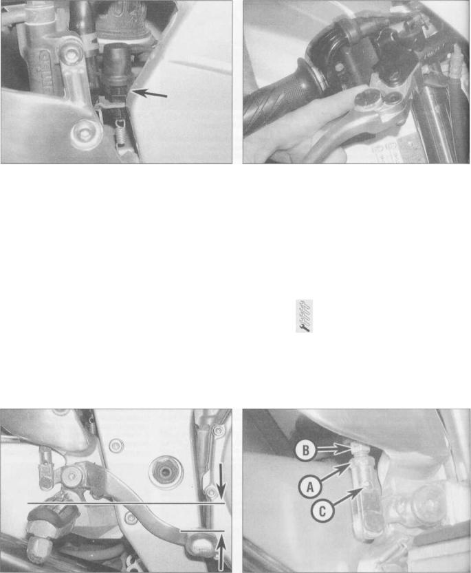
adjuster nut on the switch body until the brake light is activated when required (see illustration). If the brake light comes on too late, turn the nut clockwise. If the brake light comes on too soon or is permanently on, turn the nut anti-clockwise. If the switch doesn't operate the brake light, check it (see Chapter 9). 6 The front brake lever has a span adjuster which alters the distance of the lever from the handlebar (see illustration). Each setting is identified by a number on the adjuster which aligns with the arrow on the lever bracket. Pull the lever away from the handlebar and turn the adjuster ring until the setting which best suits the rider is obtained. There are four settings - setting one gives the largest span, and setting 4 the smallest. Make sure that the pin on the brake lever holder is firmly seated in the hole in the adjuster.
7 Check the position of the brake pedal. Yamaha recommend the distance between the top of the end of the brake pedal and the top of the rider's footpeg should be as specified at the beginning of the Chapter (see
illustration). If the pedal height is incorrect, or if the rider's preference is different, slacken the clevis locknut on the master cylinder pushrod, then turn the pushrod using a spanner on the hex on the rod until the pedal is at the correct or desired height (see illustration). After adjustment check that the pushrod end is visible in the hole in the clevis.
On completion tighten the locknut securely.
Adjust the rear brake light switch after adjusting the pedal height (see Step 5).
10Clutch-
check and adjustment
1 Check that the clutch lever operates smoothly and easily.
2 If the clutch lever operation is heavy or stiff, remove the cable (see Chapter 2) and lubricate it (see Section 18). If the cable is still stiff, fit a new one. Install the lubricated or new cable (see Chapter 2).
3 With the cable operating smoothly, checkl that the clutch lever is correctly adjusted.! Periodic adjustment is necessary to com-l pensate for wear in the clutch plates and! stretch of the cable. Check that the amount of freeplay at the clutch lever end is within thel specifications listed at the beginning of the!
Chapter (see illustration).
4 If adjustment is required, loosen thel lockring on the adjuster at the top of the cable! and turn the adjuster in or out until thel required amount of freeplay is obtained (seel illustration). To increase freeplay, turn thel adjuster in. To reduce freeplay, turn thel adjuster out. Tighten the locking ring securely.! 5 If all the adjustment has been taken up all the lever, reset the adjuster to give thai maximum amount of freeplay, then set thel release mechanism adjuster in the front| sprocket cover as described below:
6 On YZF models, remove the left-hand fairing side panel (see Chapter 8, Section 3).
7 Remove the rubber cover from the clutch release mechanism set in the engine sprocket
9.7a Measure the distance between the top of the footpeg and |
9.7b Slacken the locknut (A) and turn the pushrod using the hex |
the top of the brake pedal as shown |
(B) making sure the rod end is still visible in the hole (C) |
Every 4000 miles (6000 km) or 6 months 1-15
10.3 Measuring clutch cable freeplay |
10.4 Slacken the lockring (A) and turn the adjuster (B) as required |
cover (see illustration). Slacken the locknut on the release mechanism adjuster screw, then turn the adjuster screw in until resistance is felt, then back it off 1/4 turn (see illustration). When doing this, counter-hold the locknut as shown to prevent it from tightening and locking the adjuster. Now counter-hold the adjuster screw to prevent it turning and tighten the locknut. Replace the rubber cover (see illustration).
8 Now adjust the freeplay using the adjuster at the lever end of the cable as described in Step 4 until the freeplay is correct.
9 On YZF models, install the left-hand fairing side panel (see Chapter 8).
Caution: Be extremely careful when handling or working around the battery. The electrolyte is very caustic and an explosive gas (hydrogen) is given off when the battery is charging.
3 If the machine is not in regular use, disconnect the battery and give it a refresher charge every four to six weeks (see Chapter 9).
12Wheels and tyres - general check
10.7a Remove the rubber cover ...
11Batterycheck
1 All models are fitted with a sealed battery which requires no maintenance. Note: Do not attempt to remove the battery caps to check the electrolyte level or battery specific gravity. Removal will damage the caps, resulting in electrolyte leakage and battery damage.
2 All that should be done is to check that the terminals are clean and tight and that the casing is not damaged or leaking. See Chapter 9 for further details.
Tyres
1 Check the tyre condition and tread depth thoroughly - see Daily (pre-ride) checks.
Wheels
2 Cast wheels as fitted on all models are virtually maintenance free, but they should be kept clean and checked periodically for cracks and other damage. Also check the wheel runout and alignment (see Chapter 7).
Never attempt to repair damaged cast wheels; they must be replaced with new ones. Check the valve rubber for signs of damage or deterioration and have it replaced if necessary. Also, make sure the valve cap is in place and tight.
13 Wheel bearingscheck
1Wheel bearings will wear over a period of time and result in handling problems.
2Support the motorcycle upright using an auxiliary stand on YZF models or the centrestand on FZS models. Check for any play in the bearings by pushing and pulling the wheel against the hub (see illustration). Also rotate the wheel and check that it rotates smoothly.
10.7b ... then slacken the locknut using a |
10.7c On completion, replace the rubber |
ring spanner and turn the adjuster using a |
|
screwdriver as described |
cover |
13.2 Checking for play in the wheel bearings
Every 4000 miles (6000 km) or 6 months
17.9a Choke cable adjuster lockring (A) and adjuster (B) - |
17.9b Choke cable adjuster lockring (A) and adjuster (B) - |
YZF models |
FZS models |
8 If this fails to improve the operation of the choke, a new cable must be installed. Note that in very rare cases the fault could lie in the
18.3a Lubricating a cable with a pressure lubricator. Make sure the tool seals around the Inner cable
18.3b Lubricating a cable with a makeshift funnel and motor oil
carburettors rather than the cable, necessitating the removal of the carburettors and inspection of the choke plungers (see Chapter 4).
9 Make sure there is a small amount of freeplay in the cable before the plungers move. If there isn't, check that the cable is seating correctly at the carburettor end. If it is, slacken the lockring on the cable adjuster and turn the adjuster as required until there is some freeplay (see illustrations) - on FZS models, remove the fairing for improved access to the adjuster (see Chapter 8). Otherwise, renew the cable.
18Stand, lever pivots and cables - lubrication
1Since the controls, cables and various other components of a motorcycle are exposed to the elements, they should be lubricated periodically to ensure safe and trouble-free operation.
2The footrests, clutch and brake levers, brake pedal, gearshift lever linkage and sidestand/centrestand pivots should be lubricated frequently. In order for the lubricant to be applied where it will do the most good, the component should be disassembled. However, if chain and cable lubricant is being used, it can be applied to the pivot joint gaps and will usually work its way into the areas where friction occurs. If motor oil or light grease is being used, apply it sparingly as it may attract dirt (which could cause the controls to bind or wear at an accelerated rate). Note:
One of the best lubricants for the control lever pivots is a dry-film lubricant (available from many sources by different names).
3To lubricate the cables, disconnect the relevant cable at its upper end, then lubricate the cable with a pressure adapter, or if one is not available, using the set-up shown (see illustrations). See Chapter 4 for the throttle and choke cable removal procedures, and Chapter 2 for the clutch cable.
4 The speedometer cable should be removed
(see Chapter 9, Section 15) and the innel cable withdrawn from the outer cable and lubricated with motor oil or cable lubricant. Da not lubricate the upper few inches of the cable as the lubricant may travel up into the instrument head.
19 Suspension -
check
1 The suspension components must be maintained in top operating condition to ensure rider safety. Loose, worn or damaged suspension parts decrease the motorcycle's stability and control.
Front suspension
2 While standing alongside the motorcycle, apply the front brake and push on the handlebars to compress the forks several times. See if they move up-and-down smoothly without binding. If binding is felt, the forks should be disassembled and inspected
(see Chapter 6).
3 Inspect the area around the dust seal for signs of oil leakage, then carefully lever off the dust seal using a flat-bladed screwdriver and inspect the area around the fork seal (see illustrations). If leakage is evident, new seals
19.3a Lever off the dust seal...
Every 4000 miles (6000 km) or 6 months 1-19
19.3b ... and check underneath it for |
19.7a Checking for play in the swingarm |
signs of oil leakage |
bearings |
must be fitted (see Chapter 6). Check the fork tubes for scratches, corrosion and pitting as these will cause premature seal failure. If the damage is excessive new tubes should be installed (see Chapter 6).
4 Check the tightness of all suspension nuts and bolts to be sure none have worked loose, referring to the torque settings specified at the beginning of Chapter 6.
Rear suspension
5 Inspect the rear shock for fluid leakage and tightness of its mountings. If leakage is found, a newshock should be installed (see Chapter 6). 6 With the aid of an assistant to support the bike, compress the rear suspension several times. It should move up and down freely without binding. If any binding is felt, the worn or faulty component must be identified and renewed. The problem could be due to either the shock absorber, the suspension linkage components orthe swingarm components.
7 Support the motorcycle using an auxiliary stand (YZF models) or the centrestand (FZS models) so that the rear wheel is off the ground. Grab the swingarm and rock it from side to side
-there should be no discernible movement at the rear (Yamaha specify a maximum of 1 mm)
(see illustration). If there's a little movement or a slight clicking can be heard, inspect the tightness of all the rear suspension mounting bolts and nuts, referring to the torque settings specified at the beginning of Chapter 6, and recheck for movement. Next, grasp the top of the rear wheel and pull it upwards - there should be no discernible freeplay before the shock absorber begins to compress (see illustration).
Any freeplay felt in either check indicates worn bearings in the suspension linkage or swingarm, or worn shock absorber mountings. The worn components must be renewed (see Chapter 6). 8 To make an accurate assessment of the swingarm bearings, remove the rear wheel (see Chapter 7) and the bolt securing the suspension linkage rods to the swingarm (see Chapter 6). Grasp the rear of the swingarm with one hand and place your other hand at the junction of the swingarm and the frame. Try to move the rear of the swingarm from side-to-side. Any wear (play) in the bearings should be felt as movement between the swingarm and the frame at the front. If there is any play the swingarm will be felt to move forward and backward at the front (not from side-to-side). Alternatively, measure the amount of freeplay at the swingarm end - Yamaha specify a maximum of 1 mm. Next, move the swingarm up and down through its full travel. It should move freely, without any binding or rough spots. If any play in the swingarm is noted or if the swingarm does not move freely, the bearings must be removed for inspection or renewal (see Chapter 6).
20 Steering head bearings - |
ft^ |
freeplay check and adjustment
1 This motorcycle is equipped with caged ball steering head bearings which can become dented, rough or loose during normal use of the machine. In extreme cases, worn or loose
19.7b Checking for play in the suspension linkage bearings
steering head bearings can cause steering wobble - a condition that is potentially dangerous.
Check
2 Support the motorcycle in an upright position using an auxiliary stand (YZF models) or the centrestand (FZS models). Raise the front wheel off the ground either by having an assistant push down on the rear or by placing a support under the engine.
3Point the front wheel straight-ahead and slowly move the handlebars from side-to- side. Any dents or roughness in the bearing races will be felt and the bars will not move smoothly and freely.
4Next, grasp the fork sliders and try to pull and push them forward and backward (see illustration). Any looseness in the steering head bearings will be felt as front-to-rear movement of the forks. If play is felt in the bearings, adjust the steering head as follows.
Freeplay in the fork due to worn fork bushes can be misinterpreted for steering head bearing play - do not confuse the two.
Adjustment
5Displace the handlebars from the top yoke
(see Chapter 6).
6Slacken the fork clamp bolts in the top yoke (see illustration). Unscrew the steering stem nut and remove it along with its washer (see illustration).
20.4 Checking for play in the steering |
20.6a Slacken the fork clamp bolt |
20.6b ... and unscrew the steering stem |
head bearings |
(arrowed) on each side ... |
nut (arrowed) |
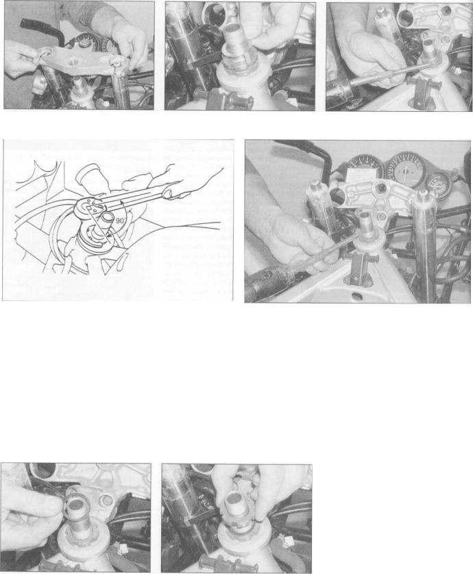
i-2o Every 4000 miles (6000 km) or 6 months
20.7 Ease the top yoke up off the steering |
20.8a Remove the tabbed lockwasher. |
20.8b . .. then unscrew the locknut |
stem and forks |
|
|
20.9 Make sure the torque wrench arm is at right angles (90°) to |
20.10 If the tool is not available, adjust the bearings as described |
the tool |
|
7Gently ease the top yoke upwards off the fork tubes and position it clear, using a rag to protect the tank or other components (see illustration).
8Remove the tabbed lockwasher, noting how it fits, then unscrew and remove the
locknut using either a C-spanner, a peg spanner or a drift located in one of the notches (see illustrations). Remove the washer (see illustration 20.11a).
9 To adjust the bearings as specified by Yamaha, a special service tool (part No.
90890-01403) and a torque wrench are required. If the tool is available, first slacken
20.11 a Fit the washer .
the adjuster nut, then tighten it to the initial torque setting specified at the beginning of the Chapter, making sure the torque wrench handle is at right angles (90°) to the line between the adjuster nut and the wrench socket in the special tool (see illustration).
Now slacken the nut so that it is loose, then tighten it to the final torque setting specified. Check that the steering is still able to move freely from side to side, but that all freeplay is eliminated.
10 If the Yamaha tool is not available, using either a C-spanner, a peg spanner or a drift located in one of the notches, slacken the
20.11b ... and the locknut
adjuster nut slightly until pressure is justl released, then tighten it until all freeplay is; removed, then tighten it a little more (see illustration). This pre-loads the bearings. Now] slacken the nut, then tighten it again, setting it so that all freeplay is just removed yet the! steering is able to move freely from side to side. To do this tighten the nut only a little at a time, and after each tightening repeat the! checks outlined above (Steps 2 to 4) until the bearings are correctly set. The object is to set j the adjuster nut so that the bearings are under, a very light loading, just enough to remove any i freeplay.
Caution: Take great care not to apply excessive pressure because this will cause premature failure of the bearings.
11 With the bearings correctly adjusted, install the washer and the locknut (see illustrations). Tighten the locknut finger-tight, then tighten it further until its notches align with those in the adjuster nut. If necessary, counter-hold the adjuster nut and tighten the locknut using a C-spanner or drift until the notches align, but make sure the adjuster nut does not turn as well. Install the tabbed lockwasher so that the tabs fit into the notches in both the locknut and adjuster nut
(see illustration 20.8a)
Every 4000 miles (6000 km) or 6 months 1-21
C
20.12a Fit the washer ... |
20.12b ... and the steering stem nut... |
20.12c ... and tighten it to the specified |
|
|
torque |
12 Fit the top yoke onto the steering stem |
both the fork clamp bolts to the specified |
|
(see illustration 20.7), then install the washer |
torque setting (see illustration). |
|
and steering stem nut and tighten it to the |
13 Check the bearing adjustment as |
|
torque setting specified at the beginning of |
described above and re-adjust if necessary. |
|
the Chapter (see illustrations). Now tighten |
14 Install the handlebars (see Chapter 6). |
|
20.12d Now tighten the fork clamp bolts to the specified torque
Every 8000 miles (12,000 km) or 12 months
Carry out all the items under the 4000 mile
(6000 km) check, plus the following:
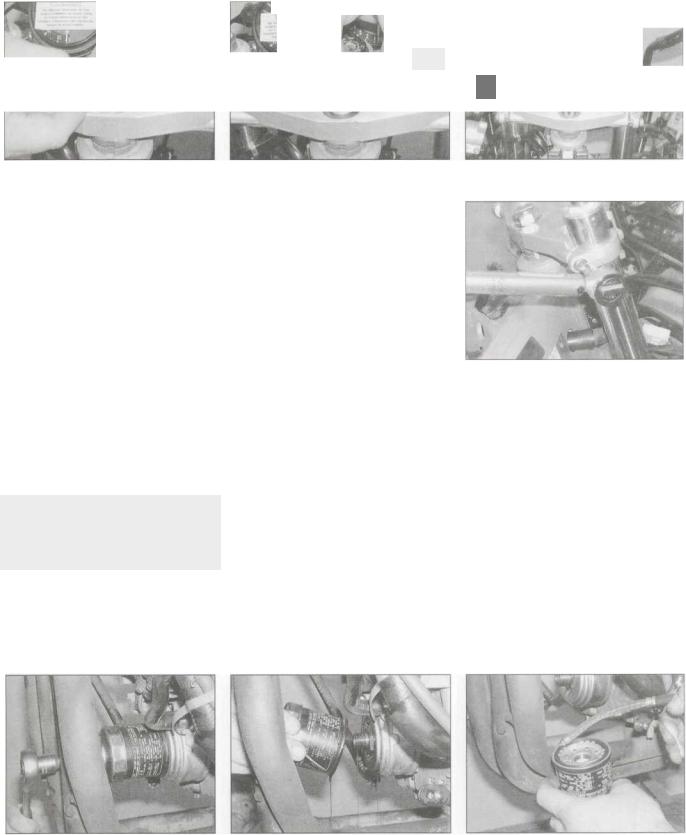
21 Engine oil and oil filter change
Warning: Be careful when draining the oil, as the exhaust pipes, the engine, and the oil itself can cause severe burns.
1On YZF models, remove the fairing side panels (see Chapter 8, Section 3).
2Drain the engine oil as described in Section 7, Steps 1 to 5.
3Now place the drain tray below the oil filter, which is on the front of the engine at the front. Unscrew the oil filter using a filter removing strap, chain or wrench and tip any residue oil into the drain tray (see illustrations). Wipe any oil off the exhaust pipes to prevent too much smoke when you start it.
4 Smear clean engine oil onto the rubber seal on the new filter, then manoeuvre it into position and screw it onto the engine until the seal just seats (see illustrations). If the correct tools are available, tighten the filter to the torque setting specified at the beginning of the Chapter (see illustration). Otherwise, tighten the filter as tight as possible by hand, or by the number of turns specified on the filter or its packaging. Note: Do not use a strap or chain filter removing tool to tighten the filter as you will damage it.
21.3a Unscrew the filter ... |
21.3b .. . and drain the oil into the tray |
21.4a Smear some clean oil onto the |
|
|
seal.. |
1 .22 Every 8000 miles (12,000 km) or 12 months
5 Refill the engine to the proper level as described in Section 7, Steps 6 to 8.
6 On YZF models, install the fairing side panels (see Chapter 8).
21.4b ... then thread the filter onto the |
21 Ac ... and tighten it as described |
cooler... |
|
Every 16,000 miles (24,000 km) or two years
Carry out all the items under the 4000 mile (6000 km) and 8000 mile (12,000 km) checks:
22Cooling system -
draining, flushing and refilling
Warning: Allow the engine to cool completely before performing this maintenance operation. Also, don't allow antifreeze to come into contact
with your skin or the painted surfaces of the motorcycle. Rinse off spills immediately with plenty of water. Antifreeze is highly toxic if ingested. Never leave antifreeze lying around in an open
22.2s Unscrew the water pump drain
plug ...
container or in puddles on the floor; children and pets are attracted by its sweet smell and may drink it. Check with local authorities (councils) about disposing of antifreeze. Many communities have collection centres which will see that antifreeze is disposed of safely. Antifreeze is also combustible, so don't store it near open flames.
Draining
1 On YZF models, remove the fairing side panels and the seat (see Chapter 8). Slacken the right-hand air duct clamp screws and twist the duct round. On FZS models remove the fuel tank (see Chapter 4). Remove the pressure cap from the radiator (YZF models)
22.2b ... and allow the coolant to drain
or filler neck (FZS models) by turning it anticlockwise until it reaches a stop (see illustrations 16.6a and 16.6b). If you hear a hissing sound (indicating there is still pressure in the system), wait until it stops. Now press down on the cap and continue turning the cap until it can be removed.
2Position a suitable container beneath the water pump. Remove the coolant drain plug from the water pump and allow the coolant to completely drain from the system (see illustrations). Retain the old sealing washer for use during flushing.
3On YZF models, now position the container beneath the cylinders, then remove the drain plugs from the cylinder block and allow the coolant to completely drain from the engine
(see illustration). Retain the old sealing
washers for use during flushing.
4 Position the container beneath the coolant reservoir and remove the filler cap. Release the clamp and detach the hose from the bottom of the reservoir and allow the coolant to completely drain (see illustrations). Fit the! hose back onto the reservoir and secure it I with the clamp.
Flushing
Note: Flushing the system with more than justl water will only be necessary if the coolant hasl not been renewed regularly and corrosion is\ apparent.
22.3 Unscrew the cylinder drain plug |
|
|
|
22.4b Coolant reservoir hose • |
|
|
|
|
|||
|
|
|
|||
22.4a Coolant reservoir hose - |
|||||
(arrowed) on each side and allow the |
|||||
coolant to drain |
YZF models |
FZS models |
|||

Every 16,000 miles (24,000 km) or 2 years 1-23
5 Flush the system with clean tap water by inserting a garden hose in the radiator or filler neck. Allow the water to run through the system until it is clear and flows cleanly out of the drain hole(s). If the radiator is extremely corroded, remove it (see Chapter 3) and have it cleaned at a radiator shop.
6 Clean the drain hole(s) then install the drain plug(s) using the old sealing washer(s).
7 Fill the cooling system with clean water mixed with a flushing compound. Make sure the flushing compound is compatible with aluminium components, and follow the manufacturer's instructions carefully.
8 Start the engine and allow it to reach normal operating temperature. Let it run for about ten minutes.
9 Stop the engine. Let it cool for a while, then cover the pressure cap with a heavy rag and turn it anti-clockwise to the first stop, releasing any pressure that may be present in the system. Once the hissing stops, push down on the cap and remove it completely.
10Drain the system once again.
11Fill the system with clean water and repeat the procedure in Steps 8 to 10.
Refilling
12Fit a new sealing washer onto the drain plug(s) and tighten it/them to the torque setting specified at the beginning of the Chapter.
13Fill the system via the radiator or filler neck with the proper coolant mixture (see this Chapter's Specifications). Note: Pour the coolant in slowly to minimise the amount of air entering the system. When the system appears full, pull the bike off its stand and shake it slightly to dissipate the coolant, then place the bike back on the stand and top the system up.
14When the system is full (all the way up to
the top of the radiator or filler neck), install the pressure cap. Now fill the coolant reservoir to the UPPER level mark (see Daily (pre-ride) checks).
15 Start the engine and allow it to idle for 2 to 3 minutes. Flick the throttle twistgrip part open 3 or 4 times, so that the engine speed rises to approximately 4000 - 5000 rpm, then stop the engine. Any air trapped in the system should have bled back to the radiator filler neck via the small-bore air bleed hoses.
16 Let the engine cool then remove the pressure cap as described in Step 1. Check that the coolant level is still up to the top of the radiator or filler neck. If it's low, add the specified mixture until it reaches the top. Refit the pressure cap.
17Check the coolant level in the reservoir and top up if necessary.
18Check the system for leaks.
19Do not dispose of the old coolant by pouring it down the drain. Instead pour it into a heavy plastic container, cap it tightly and take it into an authorised disposal site or service station - see Warning at the beginning of this Section.
20 Install the air filter housing, fuel tank, body panels and seat as required by your model (see Chapters 4 and 8).
23 Swingarm and suspension |
f^ |
linkage bearings - |
*s |
re-greasing |
^ |
1 Over a period of time the grease will harden or dirt will penetrate the bearings.
2 The rear suspension components are not equipped with grease nipples. Remove the swingarm and the suspension linkage as described in Chapter 6 for greasing of the bearings.
24Steering head bearings - lubrication
1Over a period of time the grease will harden or may be washed out of the bearings by incorrect use of jet washes.
2Disassemble the steering head for regreasing of the bearings. Refer to Chapter 6 for details.
25Brakes - fluid change
1 The brake fluid should be replaced every two years or whenever a master cylinder or caliper overhaul is carried out. Refer to the brake bleeding section in Chapter 7, noting that all old fluid must be pumped from the fluid reservoir and hydraulic line before filling with new fluid.
Old brake fluid is invariably much darker in colour than new fluid, making it easy to see when all old fluid has been expelled from the system.
26Brake caliper
and master cylinder seals - replacement
1 Brake seals will deteriorate over a period of time and lose their effectiveness, leading to sticking operation or fluid loss, or allowing the ingress of air and dirt. Refer to Chapter 7 and dismantle the components for seal replacement every two years.
Every 28,000 miles (42,000 km) or 42 months
Carry out all the items under the 4000 mile (6000 km) check, plus the following
27 Valve clearances - check and adjustment
1The engine must be completely cool for this maintenance procedure, so let the machine sit overnight before beginning.
2Remove the valve cover (see Chapter 2). Each cylinder is referred to by a number. They are numbered 1 to 4 from left to right.
3Make a chart or sketch of all valve positions so that a note of each clearance can be made against the relevant valve.
4Unscrew the bolts securing the alternator cover and remove the cover, on FZS models noting the hose guard secured by the bottom bolts (see illustrations). Remove the two
dowels for safekeeping if they are loose. The engine can be turned using a 19 mm socket on the alternator rotor bolt and turning it in an anti-clockwise direction only. Alternatively, place the motorcycle on an auxiliary stand so
27.4a Unscrew the alternator cover bolts
(arrowed)...
that the rear wheel is off the ground, select a high gear and rotate the rear wheel by hand in its normal direction of rotation.
5 Turn the engine until the line next to the "T" mark on the rotor aligns with the crankcase
27.4b ... on FZS models, noting the hose guard (arrowed)
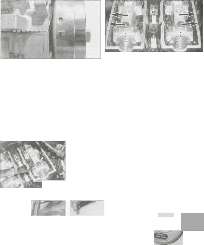
.24 Every 28,000 miles (42,000 km) or 42 months
27.5a Turn the engine until the line next to the "T" mark aligns
with the crankcase mating surfaces at the front...
27.5b ... and the dots are aligned and the camshaft lobes face away from each other (FZS model shown - on YZF models note that the intake camshaft dots are positioned slightly off the vertical, at the 1 o'clock position)
mating surfaces at the front of the engine (see illustration), the camshaft lobes for the No. 1 (left-hand) cylinder face away from each other, and the dot on the end of each camshaft aligns with the dot on the camshaft holder (see illustration). If the cam lobes are facing towards each other and the dots do not align, rotate the engine anti-clockwise 360° (one full turn) so that the line next to the "T" mark again aligns with the crankcase mating surfaces. The camshaft lobes will now be facing away from each other and the dots will be aligned, meaning the No. 1 cylinder is at TDC (top dead centre) on the compression stroke.
6 With No. 1 cylinder at TDC on the compression stroke, check the clearances on the No.1 cylinder intake and exhaust valves
(see illustration). Insert a feeler gauge of the
27.6 Measure the clearance using a feeler gauge
same thickness as the correct valve clearance
(see Specifications) between the camshaft lobe and follower of each valve and check that it is a firm sliding fit - you should feel a slight drag when the you pull the gauge out. If not, use the feeler gauges to measure the exact clearance. Record the measured clearance on the chart.
7Now turn the engine anti-clockwise 180°
(half a turn) so that the camshaft lobes for the
No. 2 cylinder are facing away from each other. The No. 2 cylinder is now at TDC on the compression stroke. Measure the clearances of the No. 2 cylinder valves using the method described in Step 6.
8Now turn the engine anti-clockwise 180° (half a turn) so that the line next to the "T" mark on the rotor again aligns with the crankcase mating surfaces, and the camshaft lobes for the No. 4 cylinder are facing away from each other. The No. 4 cylinder is now at
TDC on the compression stroke. Measure the clearances of the No. 4 cylinder valves using the method described in Step 6.
9Now turn the engine anti-clockwise 180° (half a turn) so that the camshaft lobes for the
No. 3 cylinder are facing away from each other. The No. 3 cylinder is now at TDC on the compression stroke. Measure the clearances of the No. 3 cylinder valves using the method described in Step 6.
10When all clearances have been measured and charted, identify whether the clearance on
any valve falls outside the range specified. Ifi does, the shim between the cam follower and the valve must be replaced with one of a thickness which will restore the correct clearance.
11Shim replacement requires removal of the camshafts (see Chapter 2). There is no need to remove both camshafts if shims from onl] one side of the engine need replacing. PIact rags over the spark plug holes and the cam chain tunnel to prevent a shim from droppinj into the engine on removal.
12With the camshaft removed, remove the
cam follower of the valve in question, then retrieve the shim from the inside of the follower (see illustrations). If it is not in the follower, pick it out of the top of the valve using either a magnet, a small screwdrivei with a dab of grease on it (the shim will stick to the grease), or a screwdriver and a pair d pliers (see illustration 27.15a). Do not allon the shim to fall into the engine.
13A size mark should be stamped on thi upper face of the shim - a shim marked 175 it
1.75 mm thick. If the mark is not visible thi shim thickness will have to be measured. It is recommended that the shim is measured anyway to check that it has not worn (sei illustration).
14Using the appropriate shim selectioi chart, find where the measured valvi clearance and existing shim thickness values intersect and read off the shim sizi required (see illustrations). Note: If tht
.*.•:•"'-••• |
-.. |
%» |
f |
... |
—4|
27.12a Lift out the follower ., |
27.12b . . . and remove the shim from |
|
inside the follower |
27.13 Measure the shim using a micrometer
Every 28,000 miles (42,000 km) or 42 months 1-25
INTAKE
|
MEASURED |
|
|
|
|
|
|
|
|
|
|
|
|
|
|
|
|
|
|
INSTALLED PAD NUMBER |
|
|
|
|
|
|
|
|
|
|
|
|
|
|
|||||||||||
|
CLEARANCE |
|
120 |
125 |
130 |
135 |
140 |
145 |
150 |
155 |
160 |
|
165 |
170(175 |
|
180 |
185 |
190 |
195 |
200 |
205 |
2101215 |
220 |
225 |
23C |
|
235 240 |
||||||||||||||||||
|
0.00 - 0.02 |
|
|
|
|
|
120 |
|
1l>b |
130 |
135 |
140 |
145 |
|
I5O |
155 160 |
165 |
170 |
175 |
180 |
185 |
190 |
|
T9T |
^00 |
205 |
210 21E |
|
220 225 |
||||||||||||||||
|
0.03 - 0.07 |
|
|
|
120 |
125 |
130 |
135 |
140 |
145 |
150 |
155 |
160 |
165|170 |
175 |
180 |
185 |
190 |
195 |
200 |
205 |
210 |
215 22C |
|
225 230 |
||||||||||||||||||||
|
0.08-0 .10 |
|
|
120 |
125 |
130 |
135 |
140 |
145 |
150 |
155 |
160 |
165 |
|
170(175 |
180 |
185 |
190 |
195 |
200 |
205 |
210 |
215 |
220 22E |
|
230 235 |
|||||||||||||||||||
|
0.11 -0.20 |
|
|
|
|
|
|
|
|
|
|
|
|
|
|
|
|
|
RECOMMENDED CLEARANCE |
|
|
|
|||||||||||||||||||||||
|
0.21 - 0.22 |
|
25 |
|
135 |
140 |
145 |
150 |
155 |
160 |
165 |
170 |
175 |
180 |
185 |
190 |
195 |
200 |
205 |
210 |
215 |
220 |
225 |
230 23E |
|
240) |
|||||||||||||||||||
|
|
|
1305 |
140 |
|
|
|
|
155 |
|
|
|
|
|
|
|
|
|
|
|
|
|
|
|
|
|
|
|
|
|
|
|
|
|
|
|
|
|
|
|
|||||
|
0,33 ~O7 |
|
145150 |
160 |
165 |
170 |
175 |
180 |
185 |
190 |
195 |
200 |
205 |
210 |
215 |
220 |
225 |
230 |
235 24C |
|
|
||||||||||||||||||||||||
|
0.28 - 0.32 |
135 140 |
145 |
150 155 |
160 |
165 |
170 |
175 |
180 |
185 |
190 |
195 |
200 |
205 |
210 |
215 |
220 |
225 |
230 |
235 |
240 |
|
|
|
|||||||||||||||||||||
|
|
|
|
|
|
|
|
|
|
|
|
|
|
|
|
|
|
|
|
|
|
|
|
|
|
|
|
|
|
|
|
|
|
|
|
|
|
|
|
|
|
|
|
||
|
0.33 - 0.37 |
140 145 |
150 |
155 160 |
165 |
170 |
175 |
180 |
185 |
190 |
195 |
200 |
205 |
210 |
215 |
220 |
225 |
230 |
235 |
240 |
|
|
|
|
|||||||||||||||||||||
|
0.38-0.42 |
145 |
150 |
155 |
160 165 |
170 |
175 |
180 |
185 |
190 |
195 |
200 |
205 |
210 |
215 |
220 |
225 |
230 |
235 |
240 |
|
|
|
|
|
|
|||||||||||||||||||
|
0.43 - 0.47 |
150 155 |
160 |
165 170 |
175 |
180 |
185 |
190 |
195 |
200 |
205 |
210 |
215 |
220 |
225 |
230 |
235 |
240 |
|
|
|
|
|
|
|
|
|||||||||||||||||||
|
0.48-0.52 |
155 |
160 |
165 |
170 |
175 |
180 |
185 |
190 |
195 |
200 |
205 |
210 |
215 |
220 |
225 |
230 |
235 |
240 |
|
|
|
|
|
|
|
|
|
|
||||||||||||||||
|
0.53- 0.57 |
160 165 |
170 |
175 |
180 |
185 |
190 |
195 |
200 |
205 |
210 |
215 |
220 |
225 |
230 |
235 |
240 |
|
|
|
|
|
|
|
|
|
|
|
|
||||||||||||||||
|
0.58 - 0.62 |
165 170 |
175 |
180 185 |
190 |
195 |
200 |
205 |
210 |
215 |
220 |
225 |
230 |
235 |
240 |
|
|
|
|
|
|
|
|
|
|
|
|
|
|
||||||||||||||||
|
|
|
|
|
|
|
|
|
|
|
|
|
|
|
|
|
|
|
|
|
|
|
|
|
|
|
|
|
|
|
|
|
|
|
|
|
|
|
|
|
|
|
|
||
|
0.63 - 0.67 |
170 175 |
180 |
185 190 |
195 |
200 |
205 |
210 |
215 |
220 |
225 |
230 |
235 |
240 |
|
|
|
|
|
|
|
|
|
|
|
|
|
|
|
|
|||||||||||||||
|
0.68-0.72 |
175 180 |
185 |
190 195 |
200 |
205 |
210 |
215 |
220 |
225 |
230 |
235 |
240 |
|
|
|
|
|
|
|
|
|
|
|
|
|
|
|
|
|
|
||||||||||||||
|
0.73 - 0.77 |
180 185 |
190 |
195 200 |
205 |
210 |
215 |
220 |
225 |
230 |
235 |
240 |
|
|
|
|
|
|
|
|
|
|
|
|
|
|
|
|
|
|
|
||||||||||||||
|
0.78 - 0.82 |
185 190 |
195 |
200 205 |
210 |
215 |
220 |
225 |
230 |
235 |
240 |
|
|
|
|
|
|
|
|
|
|
|
|
|
|
|
|
|
|
|
|
|
|||||||||||||
|
0.83 - 0.87 |
190 195 |
200 |
205 210 |
215 |
220 |
225 |
230 |
235 |
240 |
|
|
|
|
|
|
|
|
|
|
|
|
|
|
|
|
|
|
|
|
|
|
|
||||||||||||
|
0.88 - 0.92 |
195 200 |
205 |
210 215 |
220 |
225 |
230 |
235 |
240 |
|
|
|
|
|
|
|
|
|
|
|
|
|
|
|
|
|
|
|
|
|
|
|
|
|
|
||||||||||
|
|
|
|
|
|
|
|
|
|
|
|
|
|
|
|
|
|
|
|
|
|
|
EXAMPLE: |
|
|
|
|
|
|
|
|
|
|
|
|
|
|
|
|
||||||
|
0.93 - 0.97 |
|
200 205 |
210 |
215 220 |
225 |
230 |
235 |
240 |
|
|
|
|
|
|
|
|
|
|
|
|
|
|
|
|
|
|
|
|
|
|||||||||||||||
|
0.98- 1.02 |
|
205 210 |
215 |
220 225 |
230 |
235 |
240 |
|
|
|
|
|
|
VALVE CLEARANCE (cold): |
|
|
|
|||||||||||||||||||||||||||
|
1.03- 1-07 |
|
210 215 |
220 |
225 230 |
235 |
240 |
|
|
|
|
|
|
|
|
|
|
|
|||||||||||||||||||||||||||
|
|
|
|
|
|
|
|
|
|
|
0.11 ~ 0.20 mm (0.004 ~ 0.008 in) |
|
|
|
|||||||||||||||||||||||||||||||
|
1.08- 1.12 |
|
215 220 |
225 |
230 235 |
240 |
|
|
|
|
|
|
|
|
|
|
|
|
|
|
|||||||||||||||||||||||||
|
1.13- 1.17 |
|
220 225 |
230 |
235 240 |
|
|
|
|
|
|
|
|
|
|
|
|
|
Installed is 148 (Rounded off number is 150) |
||||||||||||||||||||||||||
|
1.18- 1.22 |
|
225 230 |
235 |
240 |
|
|
|
|
|
|
|
|
|
|
|
|
|
|
|
Measured clearance is 0.24 mm (0.009 in) |
||||||||||||||||||||||||
|
|
|
|
|
|
|
|
|
|
|
|
|
|
|
|
|
|
|
|
|
|
|
|
||||||||||||||||||||||
|
1.23- 1.27 |
|
230 235 |
240 |
|
|
|
|
|
|
|
|
|
|
|
|
|
|
|
|
|
||||||||||||||||||||||||
|
|
|
|
|
|
|
|
|
|
|
|
|
|
|
|
|
|
|
Replace 148 pad with 160 pad |
|
|
|
|||||||||||||||||||||||
|
1.28- 1.32 |
|
235 240 |
|
|
|
|
|
|
|
|
|
|
|
|
|
|
|
|
|
|
|
|
|
|
||||||||||||||||||||
|
1.33- 1.37 |
|
240 |
|
|
|
|
|
|
|
|
|
|
|
|
|
|
|
|
|
|
|
|
|
|
|
|
|
|
|
|
|
|
|
|
|
|
|
|
|
|
|
|
|
|
|
|
|
|
|
|
|
|
|
|
|
|
|
|
|
|
|
|
|
|
|
|
|
|
|
|
|
|
|
|
|
|
|
|
|
|
|
|
|
|
|
|
|
|
|
|
|
|
|
|
|
|
|
|
|
|
27.14a Shim selection chart - intake camshaft |
|
|
|
||||||||||||||||||||||||||||||||
|
EXHAUST |
|
|
|
|
|
|
|
|
|
|
|
|
|
|
|
|
|
|
|
|
|
|
|
|
|
|
|
|
|
|
|
|
|
|
|
|
|
|
|
|
|
|
|
|
|
|
|
|
|
|
|
|
|
|
|
|
|
|
|
|
|
|
|
|
|
|
|
|
|
|
|
|
|
|
|
|
|
|
|
|
|
|
|
|
||||||
|
MEASURED |
|
|
|
|
|
|
|
|
|
|
|
|
|
|
|
|
|
INSTALLED PAD NUMBER |
|
|
|
|
|
|
|
|
|
|
|
|
|
|
||||||||||||
|
CLEARANCE |
120 |
125 |
130 |
135 |
|
140 |
145 |
150 |
155 |
160 |
165ll70!W8j180 |
185 |
190 |
1951200 |
205 |
210 215 |
220 225 230 |
235 240 |
||||||||||||||||||||||||||
|
0.00 - 0.02 |
|
|
|
|
|
|
|
|
|
|
120 |
lib |
130 |
13b |
140|145;l58j155 |
1t>0 |
|
165 |
170J175 |
1tJO |
1Bb 190 |
1% |
200 205 |
210 215 |
||||||||||||||||||||
|
0.03 - 0.07 |
|
|
|
|
|
|
|
|
120 |
125 |
130 |
135 |
140 |
145 |
150 tSS>160 |
165 |
170 |
175 |
180 |
185 |
190 |
195 |
200 |
h205 |
210 |
215 220 |
||||||||||||||||||
|
0.08-0.12 |
|
|
|
|
|
|
120 |
125 |
130 |
135 |
|
140 |
145 |
150 |
155 W |
165 |
170 |
175 |
180 |
185 |
190 |
195 200 |
205 |
210 215 |
220 225 |
|||||||||||||||||||
|
0.13-0.17 |
|
|
|
|
120 |
125 |
130 |
135 |
140 |
|
145 |
150 |
155 |
160®. |
|
170 |
175 |
180 |
185 |
190 |
195 |
200 205 |
210 |
215 220 |
225 230 |
|||||||||||||||||||
|
0.18-0.20 |
|
|
120 |
125 |
130 |
135 |
140 |
145 |
|
150 |
155 |
160 |
165 |
lip' |
175 |
180 |
185 190 |
195 |
200 |
205 210 |
215 |
220 225 |
230 235 |
|||||||||||||||||||||
|
0.21 - 0.30 |
|
|
|
|
|
|
|
|
|
|
|
|
|
|
|
|
|
RECOMMENDED CLEARANCE |
|
|
|
|||||||||||||||||||||||
|
0.31 - 0.32 |
|
125 |
1301135 |
140 |
145 |
150 |
155 |
|
160 |
165 |
170 |
175 |
|
180 |
185 |
J90[195 |
200 |
205 |
210 |
215 |
220 |
225 |
2301235 |
240 |
||||||||||||||||||||
|
0.33 - 0.37 |
|
130 |
«35 |
140 |
145 |
150 |
155 |
160 |
165 |
170 |
|
175 |
180 |
res |
190 |
195 |
200 |
205 |
210 |
215 |
220 |
225 |
230 |
235 240 |
|
|||||||||||||||||||
|
0.38 - 0.42 |
135 |
140 |
145 |
150 |
155 |
160 |
165 |
170 |
175 |
180 |
185 |
190 |
195 |
200 |
205 |
210 |
215 |
220 |
225 |
230 |
235 |
240] |
|
|
|
|||||||||||||||||||
|
0.43 - 0.47 |
140 |
145 |
150 |
155 |
160 |
165 |
170 |
175 |
180 |
185 |
190 |
195 |
200 |
205 |
210 |
215 |
220 |
225 |
230 |
235 |
240 |
|
|
|
|
|||||||||||||||||||
|
0.48-0.52 |
145 |
150 |
155 |
160 |
165 |
170 |
175 |
180 |
185 |
190 |
195 |
200 |
205 |
210 |
215 |
220 |
225 |
230 |
235 |
240 |
|
|
|
|
|
|
||||||||||||||||||
|
0.53 - 0.57 |
150 |
155 |
160 |
165 |
170 |
175 |
180 |
185 |
190 |
195 |
200 |
205 |
210 |
215 |
220 |
225 |
230 |
235 |
240 |
|
|
|
|
|
|
|
|
|||||||||||||||||
|
0.58 - 0.62 |
155 |
160 |
165 |
170 |
175 |
180 |
185 |
190 |
195 |
200 |
205 |
210 |
215 |
220 |
225 |
230 |
235 |
240 |
|
|
|
|
|
|
|
|
|
|
||||||||||||||||
|
0.63 - 0.67 |
160 |
165 |
170 |
175 |
180 |
185 |
190 |
195 |
200 |
205 |
210 |
215 |
220 |
225 |
230 |
235 |
240 |
|
|
|
|
|
|
|
|
|
|
|
|
|||||||||||||||
|
0.68 - 0.72 |
165 |
170 |
175 |
180 |
185 |
190 |
195 |
200 |
205 |
210 |
215 |
220 |
225 |
230 |
235 |
240 |
|
|
|
|
|
|
|
|
|
|
|
|
|
|
||||||||||||||
|
0.73 - 0.77 |
170 |
175 |
180 |
185 |
190 |
195 |
200 |
205 |
210 |
215 |
220 |
225 |
230 |
235 |
240 |
|
|
|
|
|
|
|
|
|
|
|
|
|
|
|
|
|||||||||||||
|
0.78 - 0.82 |
175 |
180 |
185 |
190 |
195 |
200 |
205 |
210 |
215 |
220 |
225 |
230 |
235 |
240 |
|
|
|
|
|
|
|
|
|
|
|
|
|
|
|
|
|
|
||||||||||||
|
0.83 - 0.87 |
180 |
185 |
190 |
195 |
200 |
205 |
210 |
215 |
220 |
225 |
230 |
235 |
240 |
|
|
|
|
|
|
|
|
|
|
|
|
|
|
|
|
|
|
|
||||||||||||
|
0.88 - 0.92 |
185 |
190 |
195 |
200 |
205 |
210 |
215 |
220 |
225 |
230 |
235 |
240 |
|
|
|
|
|
|
|
|
|
|
|
|
|
|
|
|
|
|
|
|
|
|||||||||||
|
0.93 - 0.97 |
190 |
195 |
200 |
205 |
210 |
215 |
220 |
225 |
230 |
235 |
240 |
|
|
|
|
|
|
|
|
|
|
|
|
|
|
|
|
|
|
|
|
|
|
|
||||||||||
|
0.98- 1.02 |
195 |
200 |
205 |
210 |
215 |
220 |
225 |
230 |
235 |
240 |
|
|
|
|
|
|
|
|
|
|
|
|
|
|
|
|
|
|
|
|
|
|
|
|
|
|||||||||
|
1.03- 1.07 |
|
200 |
205 |
210 |
215 |
220 |
225 |
230 |
235 |
240 |
|
|
|
|
|
|
EXAMPLE: |
|
|
|
|
|
|
|
|
|
|
|
|
|
|
|
|
|||||||||||
|
1.08- 1.12 |
|
205 |
210 |
215 |
220 |
225 |
230 |
235 |
|
240 |
|
|
|
|
|
|
|
VALVECLEARANCE(cold): |
|
|
|
|||||||||||||||||||||||
|
1.13- 1.17 |
|
210 |
215 |
220 |
225 |
230 |
235 |
240 |
|
|
|
|
|
|
|
|
|
|
|
|
||||||||||||||||||||||||
|
|
|
|
|
|
|
|
|
|
|
0.21 ~ 0.30 mm (0.008 ~ 0.012 in) |
|
|
|
|||||||||||||||||||||||||||||||
|
1.18- 1.22 |
|
215 |
220 |
225 |
230 |
235 |
240 |
|
|
|
|
|
|
|
|
|
|
|
|
|
|
|||||||||||||||||||||||
|
1.23- 1.27 |
|
220 |
225 |
230 |
235 |
240 |
|
|
|
|
|
|
|
|
|
|
|
|
|
Installed is 175 |
|
|
|
|||||||||||||||||||||
|
1.28 - 1.32 |
|
225 |
230 |
235 |
240 |
|
|
|
|
|
|
|
|
|
|
|
|
|
|
|
Measured clearance is 0.35 mm (0.014 in) |
|||||||||||||||||||||||
|
1.33- 1.37 |
|
230 |
235 |
240 |
|
|
|
|
|
|
|
|
|
|
|
|
|
|
|
|
|
|||||||||||||||||||||||
|
|
|
|
|
|
|
|
|
|
|
|
|
|
|
|
|
|
|
Replace 175 pad with 185 pad |
|
|
|
|||||||||||||||||||||||
|
1.38- 1.42 |
|
235 |
240 |
|
|
|
|
|
|
|
|
|
|
|
|
|
|
|
|
|
|
|
|
|
|
|||||||||||||||||||
|
1.43- 1.47 |
|
240 |
|
|
|
|
|
|
|
|
|
|
|
|
|
|
|
|
|
|
|
|
|
|
|
|
|
|
|
|
|
|
|
|
|
|
|
|
|
|
|
|
|
|
|
|
|
|
|
|
|
|
|
|
|
|
|
|
|
|
|
|
|
|
|
|
|
|
|
|
|
|
|
|
|
|
|
|
|
|
|
|
|
|
|
|
|
|
|
|
27.14b Shim selection chart - exhaust camshaft
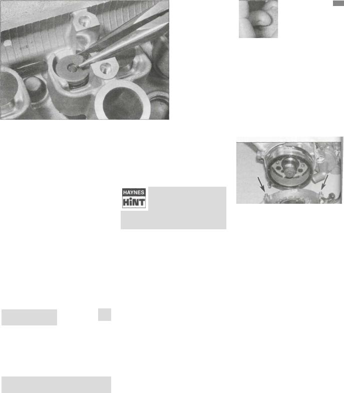
.26 Every 28,000 miles (42,000 km) or 42 months
i
27.15a Fit the shim into the recess in the top of the valve ... |
27.15b ... |
then install the follower |
existing shim is marked with a number not ending in 0 or 5, round it up or down as appropriate to the nearest number ending in 0 or 5 so that the chart can be used. Shims are available in 0.05 mm increments from 1.20 mm to 2.40 mm. Note: If the required replacement shim is greater than 2.40 mm (the largest available), the valve is probably not seating correctly due to a build-up of carbon deposits and should be checked and cleaned or resurfaced as required (see Chapter2).
15 Obtain the replacement shim, then lubricate it with molybdenum disulphide grease and fit it into its recess in the top of the valve, with the size marking on each shim facing up (see illustration).Check that the shim is correctly seated, then lubricate the follower with molybdenum disulphide oil (a 50/50 mixture of molybdenum disulphide grease and engine oil) and install it onto the valve (see illustration). Repeat the process
for any other valves until the clearances are correct, then install the camshafts (see Chapter 2).
16 Rotate the crankshaft several turns to seat the new shim(s), then check the clearances again.
It is worthwhile noting down all the valve shim thicknesses to save time and expense when the valve
clearances are next adjusted; provided they are not worn of damaged, the shims can be moved to other locations.
17 Install all disturbed components in a reverse of the removal sequence. Tighten the alternator cover bolts to the torque setting specified at the beginning of the Chapter, not forgetting the dowels if removed (see illustration), and the hose guard on FZS models (see illustration 27.4b).
27.17 Make sure the dowels (arrowed) are in place when installing the cover
Every four years
28Brake hoses- replacement
1 The hoses will in time deteriorate with age
and should be replaced every four years regardless of their apparent condition.
2 Refer to Chapter 7 and disconnect the brake hoses from the master cylinders and calipers. Always replace the banjo union sealing washers with new ones.
Non-scheduled maintenance
29 Headlight aim - |
^ |
check and adjustment
Note: An improperly adjusted headlight may cause problems for oncoming traffic or provide poor, unsafe illumination of the road ahead. Before adjusting the headlight aim, be
sure to consult with local traffic laws and regulations - for UK models refer to MOT Test Checks in the Reference section.
1 The headlight beam can adjusted both horizontally and vertically. Before making any adjustment, check that the tyre pressures are correct and the suspension is adjusted as required. Make any adjustments to the headlight aim with the machine on level
ground, with the fuel tank half full and with assistant sitting on the seat. If the bike usually ridden with a passenger on the bai have a second assistant to do this.
2 On YZF models, vertical adjustment made by turning the adjuster screw on 1 bottom left corner of the headlight unit (s illustration). Turn it clockwise to lower' beam, and anti-clockwise to raise

Non-scheduled maintenance 1-2?
29.2 Vertical adjuster (A), horizontal adjuster (B) - |
29.3 Vertical adjusters (A), horizontal adjusters (B) • |
YZF models |
FZS models |
Horizontal adjustment is made by turning the adjuster screw on the top right corner of the headlight unit. Turn it clockwise to move the beam to the right, and anti-clockwise to move it to the left.
3 On FZS models, vertical adjustment is made by turning the adjuster screw on the bottom inner corner of each headlight unit (see illustration). Turn it anti-clockwise to raise the beam, and clockwise to lower it. Horizontal adjustment is made by turning the adjuster screw on the top outer corner of each headlight unit. For the left-hand beam, turn it clockwise to move the beam to the left, and anti-clockwise to move it to the right. For the right-hand beam, turn it clockwise to move the beam to the right, and anti-clockwise to move it to the left.
30 Cylinder compression - check
1 Among other things, poor engine performance may be caused by leaking valves, incorrect valve clearances, a leaking head gasket, or worn pistons, rings and/or cylinder walls. A cylinder compression check will help pinpoint these conditions and can also indicate the presence of excessive carbon deposits in the cylinder heads.
2 The only tools required are a compression gauge and a spark plug wrench. A compression gauge with a threaded end for the spark plug hole is preferable to the type which requires hand pressure to maintain a tight seal. Depending on the outcome of the initial test, a squirt-type oil can may also be needed. 3 Make sure the valve clearances are correctly set (see Section 27) and that the cylinder head nuts are tightened to the correct torque setting (see Chapter 2).
4 Refer to Fault Finding Equipment in the
Reference section for details of the compression test. Refer to the specifications at
the beginning of the Chapter for compression figures.
31 Engine oil pressure - |
|
check |
<K |
1None of the models covered in this manual are fitted with an oil pressure switch and warning light, only an oil level sensor and light (see Chapter 9 for further information). If a lubrication problem is suspected, first check the oil level (see Daily (pre-ride) checks).
2If the oil level is correct, an oil pressure check must be carried out. The check provides useful information about the condition of the engine's lubrication system.
3To check the oil pressure, a suitable gauge and adapter piece (which screws into the crankcase) will be needed. Yamaha provide a kit (part nos. 90890-03153 and 90890-03139) for this purpose.
4Warm the engine up to normal operating temperature then stop it.
5Place a suitable container below the main
oil gallery plug, which is below the starter clutch cover on the right-hand side of the engine, to catch any oil (see illustration). Unscrew the plug and swiftly screw the adapter into the crankcase threads. Connect the gauge to the adapter. If oil is lost, replenish it to the correct level before proceeding (see Daily (pre-ride) checks).
6Start the engine and increase the engine speed to 10,000 rpm whilst watching the gauge reading. The oil pressure should be similar to that given in the Specifications at the start of this Chapter.
7Stop the engine and unscrew the gauge and adapter from the crankcase.
8Install the main oil gallery plug using a new
sealing washer, and tighten it to the torque setting specified at the beginning of the
Chapter. Check the oil level (see Daily (preride) checks).
9If the pressure is significantly lower than the standard, either the pressure regulator is stuck open, the oil pump is faulty, the oil strainer or filter is blocked, or there is other engine damage. Begin diagnosis by checking the oil filter, strainer and regulator, then the oil pump (see Chapter 2). If those items check out okay, chances are the bearing oil clearances are excessive and the engine needs to be overhauled.
10If the pressure is too high, either an oil passage is clogged, the regulator is stuck closed or the wrong grade of oil is being used.
11Refer to Chapter 2 and rectify any problems before running the engine again.
12If the oil pressure and oil level are both good, then the oil level sensor or its warning
light may be faulty. Check them and the circuit and replace with a new one if necessary (see Chapter 9).
32Fuel hoses - replacement
Warning: Petrol (gasoline) is extremely flammable, so take extra precautions when you work
on any part of the fuel system. Don't smoke or allow open flames or bare light bulbs
31.5 Main oil gallery plug (arrowed)
 Loading...