


FOREWORD
This Assembly Manual contains the information required for the correct reassembly of this Yamaha motorcycle prior to delivery to the customer. Since some external parts of the motorcycle have been removed at the Yamaha factory for the convenience of packing, assembly by the Yamaha dealer is required. It should be noted that the reassembled motorcycle should be throughly cleaned, inspected, and adjusted prior to delivery to the customer.
NOTICE
The service specifications given in this assembly manual are based on the model as manufactured. Modifications and significant changes in specifications and/or procedures will be forwarded to Authorized Yamaha Dealers. The procedures below are described in the order that the procedures are carried out correctly and completely.Failure to do so can result in poor performance and possible harm to the motorcycle and/or rider.
Particularly important information is distinguished in this manual by the following notations.
The Safety Alert Symbol means ATTENTION! BECOME ALERT! YOUR SAFETY IS INVOLVED!
 WARNING
Failure to follow WARNING instructions could result in severe injury or death to the motorcycle operator, a bystander, or a person inspecting or repairing the motorcycle.
CAUTION:
A CAUTION indicates special precautions that must be taken to avoid damage to the motorcycle.
NOTE:
A NOTE provides key information to make procedures easier or clearer.
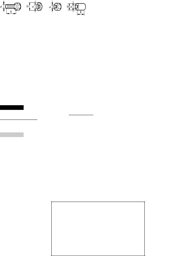
SYMBOLS USED IN
ASSEMBLY MANUAL
In order to simplify descriptions in assembly manuals, the following symbols are used:
: Coat with lithium soap base grease.
: Tighten to 10 Nm. (10 Nm = 1.0 m kg)
: Front ward of the motorcycle.
: Provide a clearance.
: Install so that the arrow mark faces upward.
: Apply a motor oil.
: Made of rubber or plastics.
A:Ref No. (indicating the order or operations.)
B:Part name
C:Quantity of parts per motorcycle.
D:Place where parts are held.
V:Stored in vinyl bag.
C:Stored in carton box.
S:Fixed inside the steel frame and/or contained in the styrofoam tray (upper or lower).
 : Temporarily installed or secured.
E:Size or material of parts. d/D: Diameter of part.: Length of part.
ex, 5 = 5 mm
FZS1000 (N) 2001
ASSEMBLY MANUAL
2000 by Yamaha Motor Co., Ltd. First Edition, December 2000
All rights reserved. Any reproduction or unauthorized use without the written permission of Yamaha Motor Co., Ltd. is expressly prohibited.
Printed in BELGIUM
FZS1000 (N) 2001
SET-UP AND PREDELIVERY CHECKLIST
NOTE:
Check the following items again when set up and predelivery service are completed.
A: INSTALLATION OF THE PARTS INCLUDED IN THE CRATE
Handlebar |
Clutch cable |
|
Throttle grip |
Band |
|
Front wheel |
Rear view mirror |
|
Windscreen |
||
Front fender |
||
Inner panel |
||
Front brake hose clamp |
||
Side cover (left) |
||
Front brake master cylinder |
||
Battery |
||
|
Handlebar switch (left)
B:TIGHTENING TORQUE OF EACH PART
Handlebar holder (upper) |
28 Nm (2.8 m kg) |
Front fender and outer tube |
10 Nm (1.0 m kg) |
Front wheel axle |
59 Nm (5.9 m kg) |
Front wheel axle pinch bolt |
20 Nm (2.0 m kg) |
Master cylinder and bracket |
10 Nm (1.0 m kg) |
Side cover |
4 Nm (0.4 m kg) |
|
|
C: ROUTING OF WIRE, CABLES, ETC. |
|
|
|
Throttle cables |
Right handlebar switch lead |
Brake hose |
Battery positive lead |
Clutch cable |
Battery negative lead |
Left handlebar switch lead |
Starter cable |
|
|
D: ADJUSTMENTS |
|
|
|
Checking and charging the battery |
Checking the brake fluid level |
Drain the fuel |
Breeding the hydraulic brake system |
Checking the tire pressure |
Adjusting the clutch cable free play |
Checking the engine oil level |
Adjusting the front fork legs |
Checking the coolant level |
Adjusting the rear shock absorber assembly |
Adjusting the engine idling speed |
Adjusting the drive chian slack |
Adjusting the throttle cable free play |
Adjusting the rear brake light switch |
Adjusting the front brake |
Adjusting the headlight beams |
Adjusting the rear brake |
Adjusting the digital clock |

E:FUNCTION AND PERFORMANCE
Check for the function of headlight, meter light and tail light
Check for the funciton of brake light
Check for the function of flasher light and indicator light
Check for the tone quality of the horn
Check for the function of the indicator on the speedometer
Check for brake feeling
Check for engine noise (Yes/No)
Check for exhaust leak (Yes/No)
F:ACCESSORIES, ETC. FOR DELIVERY
Owner's manual
Owner's tool kit

SETUP PROCEDURES
±1±

1.Handlebar
2.Throttle grip
1 |
|
Handlebar |
1 |
C |
|
|
|
|
|
|
|
2 |
|
Handlebar holder |
2 |
V |
|
|
|
|
|
|
|
3 |
|
Hexagon socket bolt |
4 |
V |
d = 8, = 30 |
|
|
|
|
|
|
4 |
|
Plug |
4 |
V |
|
|
|
|
|
|
|
A: The handlebar holder should be |
|
|
|
||
|
Tightening torque: |
||||
|
installed with the arrow mark |
|
|||
|
|
23 Nm (2.3 m kg) |
|||
|
forward. |
|
|||
|
|
|
|
||
CAUTION:
First tighten the bolts on the front side, and then tighten the bolts on the rear side.
B:Align the punch mark on the handlebar with the top of the lower handlebar holder.
C:Tighten the bolts to specified torque.
1 |
Throttle grip |
1 |
|
|
|
|
|
|
|
2 |
Screw |
1 |
|
d = 5, = 30 |
|
|
|
|
|
3 |
Screw |
1 |
|
d = 5, = 50 |
|
|
|
|
|
4 |
Grip end |
1 |
V |
|
|
|
|
|
|
A:Align the projection on the handlebar switch with the hole in the handlebar.
B:Tighten the bolt to specified torque.
Tightening torque
3.5Nm (0.4 m kg)
C:Check the throttle grip for smooth action.
CAUTION:
Proper cable routing is essential to assure safe motorcycle operation.
Refer to ªCABLE ROUTINGº.
±2±
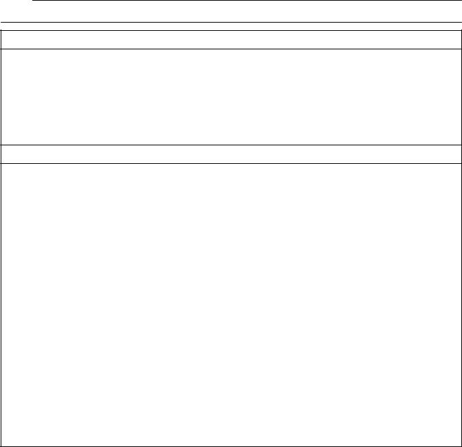
3.Front wheel
4.Front fender
1 |
Front wheel |
1 |
S |
|
|
|
|
|
|
2 |
Collar |
2 |
V |
|
|
|
|
|
|
3 |
Front wheel axle |
1 |
|
|
|
|
|
|
|
4 |
Axle pinch bolt |
1 |
|
d = 8, = 45 |
|
|
|
|
|
A:Clean the brake disc.
B:Clean the front wheel axle.
C:Clean the collar.
D:
 WARNING
Take care not to put grease on the brake disc or inner surface of the brake pads. If you do so, clean using a rag dampened with a solvent. Foreign material on braking surface can cause impaired braking action.
E:Lift the front wheel and install the front wheel axle.
F:Tighten the front wheel axle to specified torque.
Tightening torque: 72 Nm (7.2 m kg)
CAUTION:
Before tightening the pinch bolt, stroke the front forks several times to make sure of proper fork operation. With the pinch bolt loose, work the left fork leg back and forth until the proper clearance between the disc and caliper bracket on the front fork are obtained.
G:Tighten the axle pinch bolt to specified torque.
Tightening torque: 23 Nm (2.3 m kg)
1 |
Front fender |
1 |
C |
|
|
|
|
|
|
2 |
Flange bolt |
2 |
V |
d = 6, = 9 |
|
|
|
|
|
3 |
Nut |
2 |
V |
d = 6 |
|
|
|
|
|
4 |
Screw |
2 |
V |
d = 6, = 61 |
|
|
|
|
|
A:Tighten the nuts to specified torque.
Tightening torque:
6Nm (0.6 m kg)
B:Tighten the screw to specified torque.
Tightening torque: 6 Nm (0.6 m kg)
±3±
5.Front brake hose clamp
6.Front brake master cylinder
1 |
Brake hose clamp (right) |
1 |
V |
|
|
|
|
|
|
2 |
Brake hose clamp (left) |
1 |
V |
|
|
|
|
|
|
3 |
Flange bolt |
2 |
V |
d = 6, = 25 |
|
|
|
|
|
A:Install the brake hose clamp on the right side brake hose.
B:Install the brake hose clamp on the left side brake hose.
C:Pass the brake hose through the brake hose holder and secure the holder to the front fork.
CAUTION:
Proper hose routing is essential to assure safe motorcycle operation.
Refer to ªCABLE ROUTINGº.
1 |
Master cylinder |
1 |
|
|
|
|
|
|
|
2 |
Bracket |
1 |
V |
|
|
|
|
|
|
3 |
Hexagon socket bolt |
2 |
V |
d = 6, = 10 |
|
|
|
|
|
4 |
Brake switch lead |
2 |
|
|
|
|
|
|
|
A:Make sure that the ªUPº mark with the bracket is pointed upward.
B:Align the punch mark on the handlebar with the gap of the master cylinder bracket.
C:Tighten the bolts in stages and maintain an equal gap on each side of the bracket.
Tightening torque: 10 Nm (1.0 m kg)
D:Check the brake lever for smooth action.
CAUTION:
Proper cable and hose routing is essential to assure safe motorcycle operation. Refer to ªCABLE ROUTINGº.
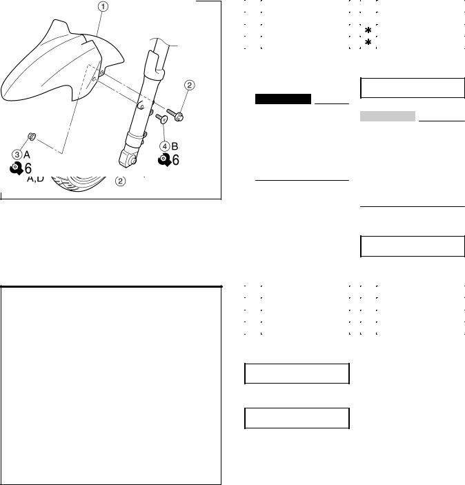
7.Handlebar switch (left)
1 |
Starter cable |
1 |
|
|
|
|
|
|
|
2 |
Starter lever |
1 |
V |
|
|
|
|
|
|
3 |
handlebar switch (left) |
1 |
|
|
|
|
|
|
|
4 |
Panhead screw |
2 |
C |
d = 5, = 25 |
|
|
|
|
|
A: Align the projection on the handlebar switch (left) with the hole in the handlebar.
CAUTION:
Proper cable routing is essential to assure safe motorcycle operation.
Refer to ªCABLE ROUTINGº.
±4±
8.Clutch cable
9.Band
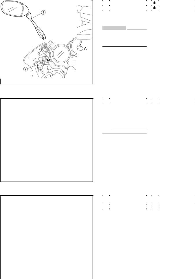
10. Rear view mirror
1 |
Clutch cable |
1 |
|
|
|
|
|
|
|
2 |
Clutch switch coupler |
1 |
|
|
A:Check the clutch lever for smooth action.
CAUTION:
Proper cable routing is essential to assure safe motorcycle operation.
Refer to ªCABLE ROUTINGº.
1 |
Band |
2 |
V |
|
|
|
|
|
|
A:Clamp the left handlebar switch lead.
B:Clamp the right handlebar switch lead.
NOTE:
Refer to ªCABLE ROUTINGº.
1 |
Rear view mirror |
2 |
C |
|
(left and right) |
|
|||
|
|
|
|
|
|
|
|
|
|
2 |
Cap nut |
4 |
V |
d = 6 |
|
|
|
|
|
±5±
 Loading...