


FZ6-ST
Table of contents
 Loading...
FZ6-ST
5VX-28197-11
SUPPLEMENTARY
SERVICE MANUAL
LIT-11616-18-43
FZ6-STC
FZ6-ST/ FZ6-STC
SUPPLEMENTARY
SERVICE MANUAL
© 2004 by Yamaha Motor
Corporation, U.S.A.
First edition, August 2004
All rights reserved. Any reproduction
or unauthorized use without the written
permission of Yamaha Motor Corporation,
U.S.A. is expressly prohibited.
Printed in U.S.A.
P/ N LIT-11616-18-43
EAS00010
FOREWORD
This Supplementary Service Manual has been prepared to introduce new service and data for the
FZ6-ST/FZ6-STC. For complete service information procedures it is necessary to use this Supple-
mentary Service Manual together with the following manual.
FZ6-SS/FZ6-SSC SERVICE MANUAL: LIT-11616-17-50 (5VX-28197-10)
EAS00002
NOTICE
This manual was produced by the Yamaha Motor Company, Ltd. primarily for use by Yamaha deal-
ers and their qualified mechanics. It is not possible to include all the knowledge of a mechanic in one
manual. Therefore, anyone who uses this book to perform maintenance and repairs on Yamaha
vehicles should have a basic understanding of mechanics and the techniques to repair these types
of vehicles.
Repair and maintenance work attempted by anyone without this knowledge is likely to render the ve-
hicle unsafe and unfit for use.
This model has been designed and manufactured to perform within certain specifications in regard
to performance and emissions. Proper service with the correct tools is necessary to ensure that the
vehicle will operate as designed. If there is any question about a service procedure, it is imperative
that you contact a Yamaha dealer for any service information changes that apply to this model. This
policy is intended to provide the customer with the most satisfaction from his vehicle and to conform
to federal environmental quality objectives.
Yamaha Motor Company, Ltd. is continually striving to improve all of its models. Modifications and
significant changes in specifications or procedures will be forwarded to all authorized Yamaha deal-
ers and will appear in future editions of this manual where applicable.
N
O
TE:
• This Service Manual contains information regarding periodic maintenance to the emission control
system. Please read this material carefully.
• Designs and specifications are subject to change without notice.
EAS00040
IMPORTANT MANUAL INFORMATION
Particularly important information is distinguished in this manual by the following.
The Safety Alert Symbol means ATTENTION! BECOME ALERT! YOUR
SAFETY IS INVOLVED!
Failure to follow WARNING instructions could result in severe injury or death
to the motorcycle operator, a bystander or a person checking or repairing the
motorcycle.
A CAUTION indicates special precautions that must be taken to avoid dam-
age to the motorcycle.
A NOTE provides key information to make procedures easier or clearer.
WARNING
CAUTION:
NOTE:
EAS00007
HOW TO USE THIS MANUAL
This manual is intended as a handy, easy-to-read reference book for the mechanic. Comprehensive
explanations of all installation, removal, disassembly, assembly, repair and check procedures are
laid out with the individual steps in sequential order.
The manual is divided into chapters. An abbreviation and symbol in the upper right corner of
each page indicate the current chapter.
Refer to “SYMBOLS”.
Each chapter is divided into sections. The current section title is shown at the top of each page,
except in Chapter 3 (“PERIODIC CHECKS AND ADJUSTMENTS”), where the sub-section title(s)
appears.
Sub-section titles appear in smaller print than the section title.
To help identify parts and clarify procedure steps, there are exploded diagrams at the start of
each removal and disassembly section.
Numbers are given in the order of the jobs in the exploded diagram. A circled number indicates a
disassembly step.
Symbols indicate parts to be lubricated or replaced.
Refer to “SYMBOLS”.
A job instruction chart accompanies the exploded diagram, providing the order of jobs, names of
parts, notes in jobs, etc.
Jobs requiring more information (such as special tools and technical data) are described
sequentially.
EAS00008
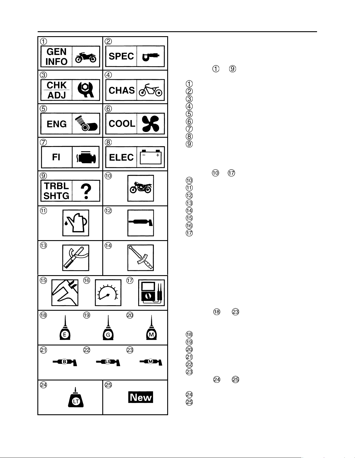
SYMBOLS
The following symbols are not relevant to every
vehicle.
Symbols to indicate the subject of each
chapter.
General information
Specifications
Periodic checks and adjustments
Chassis
Engine
Cooling system
Fuel injection system
Electrical system
Troubleshooting
Symbols to indicate the following.
Serviceable with engine mounted
Filling fluid
Lubricant
Special tool
Tightening torque
Wear limit, clearance
Engine speed
Electrical data
Symbols to in the exploded diagrams
indicate the types of lubricants and lubrication
points.
Engine oil
Gear oil
Molybdenum-disulfide oil
Wheel-bearing grease
Lithium-soap- based grease
Molybdenum-disulfide grease
Symbols to in the exploded diagrams
indicate the following.
Apply locking agent (LOCTITE
®
)
Replace the part

CONTENTS
SPECIFICATIONS
GENERAL SPECIFICATIONS . . . . . . . . . . . . . . . . . . . . . . . . . . . . . . 1
ENGINE SPECIFICATIONS . . . . . . . . . . . . . . . . . . . . . . . . . . . . . . . . 1
CHASSIS SPECIFICATIONS . . . . . . . . . . . . . . . . . . . . . . . . . . . . . . . 1
ELECTRICAL SPECIFICATIONS . . . . . . . . . . . . . . . . . . . . . . . . . . . . 1
TIGHTENING TORQUES . . . . . . . . . . . . . . . . . . . . . . . . . . . . . . . . . . 2
ENGINE TIGHTENING TORQUES . . . . . . . . . . . . . . . . . . . . . . . . 2
CHASSIS TIGHTENING TORQUES . . . . . . . . . . . . . . . . . . . . . . . 2
CABLE ROUTING . . . . . . . . . . . . . . . . . . . . . . . . . . . . . . . . . . . . . . . . 3
CHASSIS
SWINGARM AND DRIVE CHAIN . . . . . . . . . . . . . . . . . . . . . . . . . . . . 14
CHECKING THE DRIVE CHAIN . . . . . . . . . . . . . . . . . . . . . . . . . . 14
ENGINE
ENGINE . . . . . . . . . . . . . . . . . . . . . . . . . . . . . . . . . . . . . . . . . . . . . . . . 16
INSTALLING THE ENGINE . . . . . . . . . . . . . . . . . . . . . . . . . . . . . . 16
CONNECTING RODS AND PISTONS . . . . . . . . . . . . . . . . . . . . . . . . 18
REMOVING THE CONNECTING RODS AND PISTONS . . . . . . . 19
CHECKING THE BIG END BEARINGS. . . . . . . . . . . . . . . . . . . . . 20
INSTALLING THE CONNECTING ROD AND PISTON . . . . . . . . . 24

SPEC
1
SPECIFICATIONS
GENERAL SPECIFICATIONS
ENGINE SPECIFICATIONS
CHASSIS SPECIFICATIONS
ELECTRICAL SPECIFICATIONS
Item Standard Limit
Model code
5VX8 (USA except for CAL)
5VX9 (CAL)
•
• •
•
• •
Item Standard Limit
Piston
Diameter D 65.475 ~ 65.490 mm (2.5778 ~ 2.5783
in)
•
• •
Height H 5 mm (0.20 in) •
• •
Item Standard Limit
Drive chain
Model (manufacturer) 50V4 (DAIDO) •
• •
Link quantity 118 •
• •
Drive chain slack 45 ~ 55 mm (1.77 ~ 2.17 in) •
• •
Maximum 15-link section •
• • 239.3 mm
(9.42 in)
Item Standard Limit
Ignition system
T.C.I. unit model (manufacturer) F8T812 (MITSUBISHI) (USA) •
• •
F8T813 (MITSUBISHI) (CAL) •
• •
Starting circuit cut-off relay
Model (manufacture) G8R-30Y-V3 (OMRON) •
• •
Coil resistance 162 ~ 198 Ω •
• •
GENERAL SPECIFICATIONS / ENGINE SPECIFICATIONS /
CHASSIS SPECIFICATIONS / ELECTRICAL SPECIFICATIONS
SPEC
2
TIGHTENING TORQUES
ENGINE TIGHTENING TORQUES
CHASSIS TIGHTENING TORQUES
Item Fastener
Thread
size
Q’ty
Tightening torque
Remarks
Nm m•kg ft•lb
Connecting rod caps Bolt M7 8
15+120°
1.5+120°
11+120°
Item
Thread
size
Tightening torque
Remarks
Nm m•kg ft•lb
Pivot shaft and frame M18 125 12.5 90
Sidestand switch nut M5 4 0.4 2.9
Shift rod and shift arm bolt M6 10 1.0 7.2
Footrest bracket and footrest cover plate M5 7 0.7 5.1
TIGHTENING TORQUES
SPEC
3
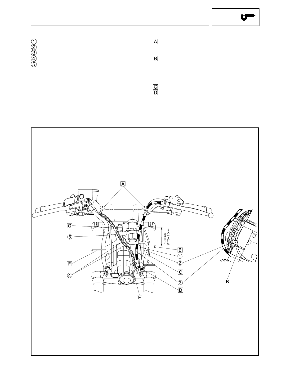
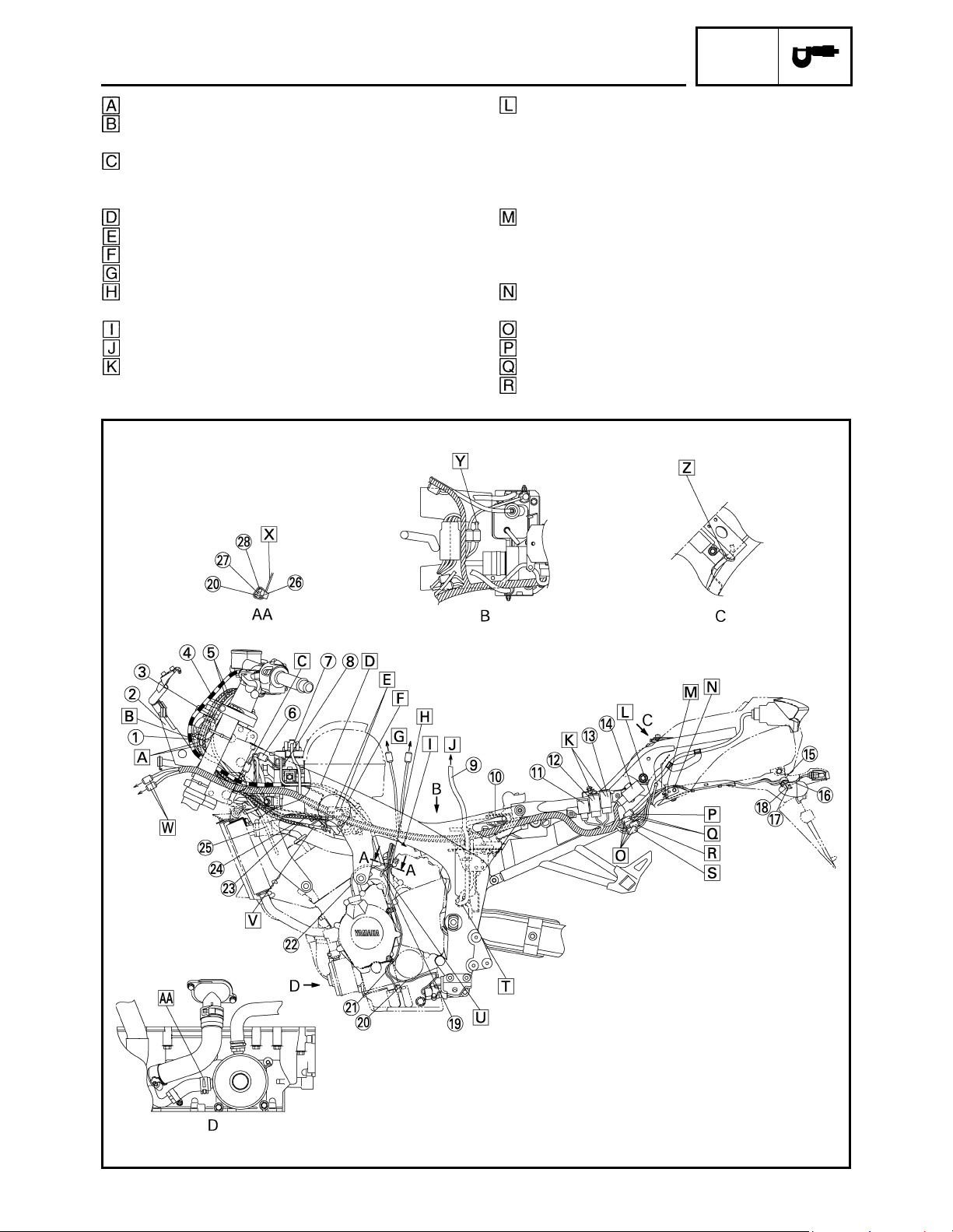
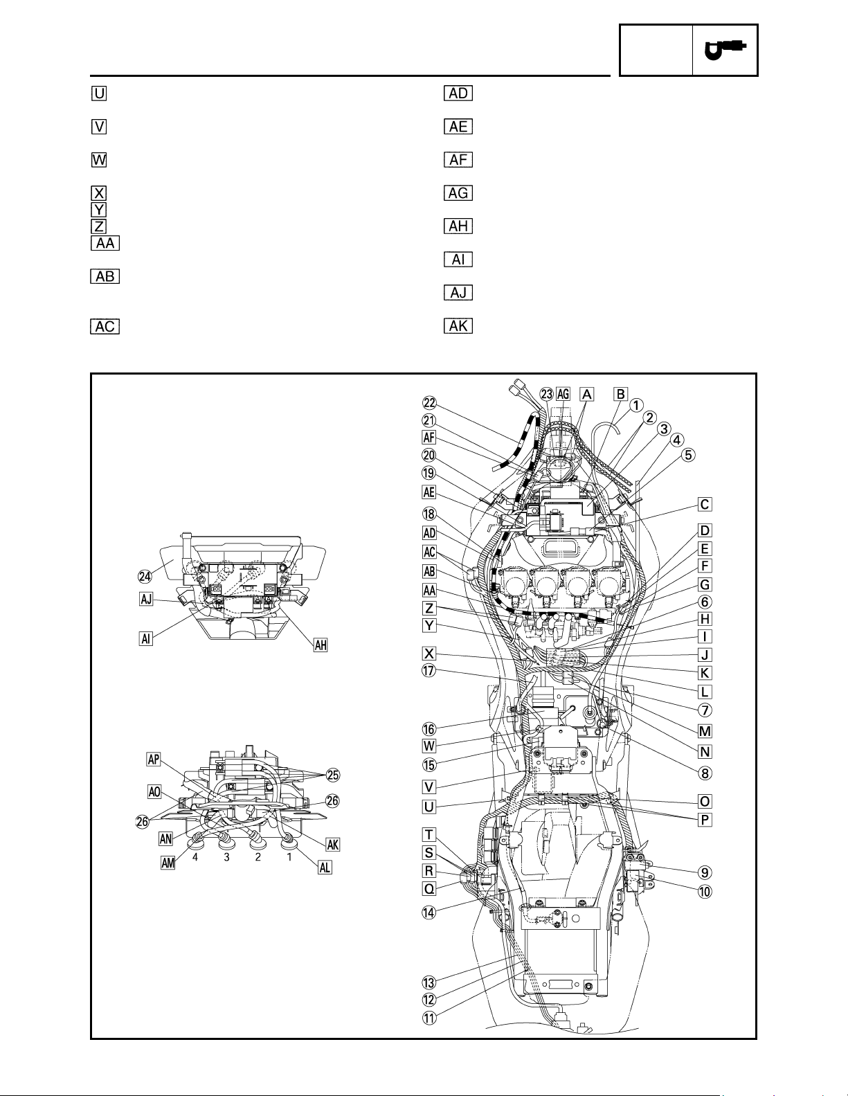
CABLE ROUTING
Left handlebar switch lead
Main switch lead
Clutch cable
Throttle cables
Right handlebar switch lead
Clamp the right and left handlebar switch leads
and handlebars. Point the tip of the clamp
downward in front of the handlebars.
Clamp the horn lead and main switch lead
(upper side only) to the inner tube. Point the
binding section to the outside of the vehicle
body and cut the tip down to the length of 1 to 5
mm (0.04 to 0.20 in).
Route the horn lead by the headmost side.
Pass the throttle cables, wire harness lead,
clutch cable, main switch and immobilizer lead
and left handlebar switch lead in order through
the frame hole from the inner side of the vehicle.
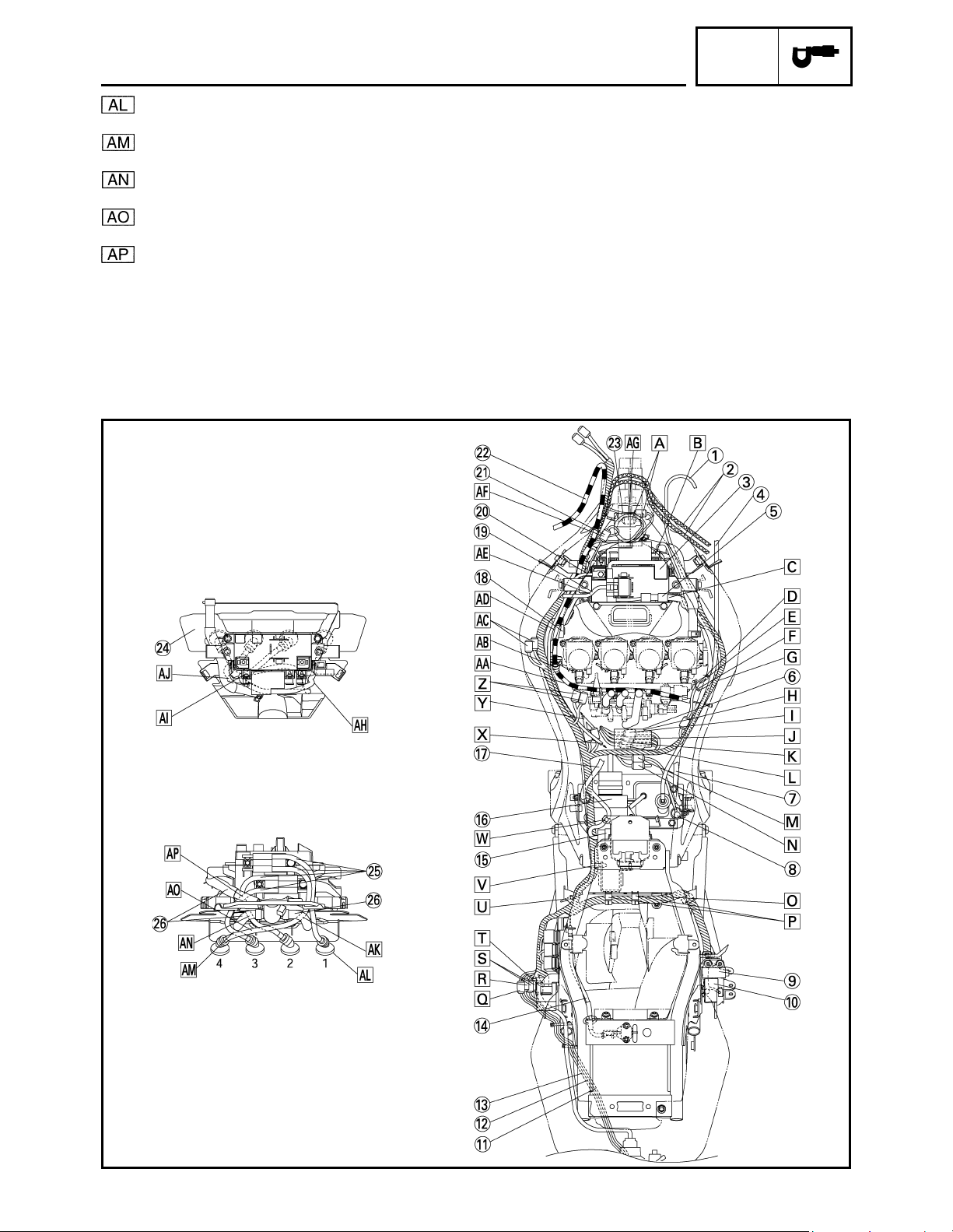
CABLE ROUTING
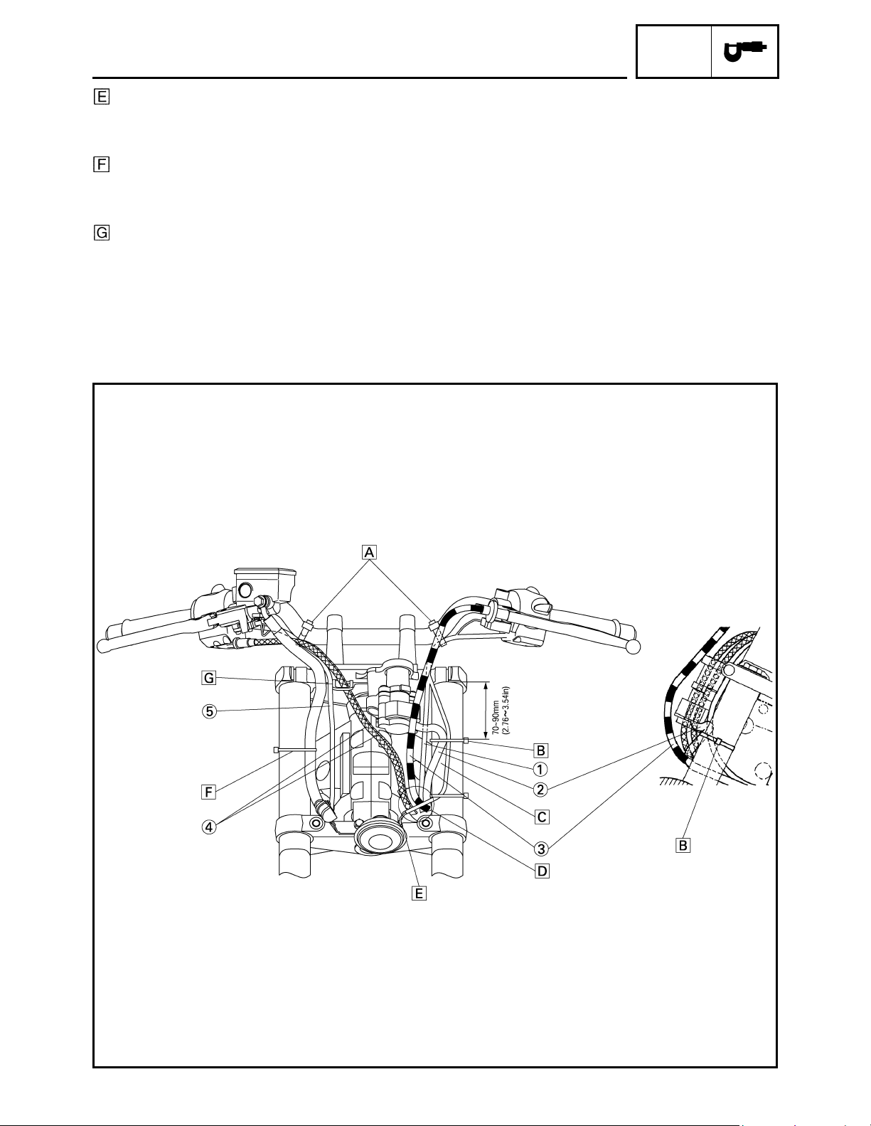
SPEC
4
Point the lead, which comes from the terminal,
to the front side of the vehicle body. There
should be no slack of leads between the band
and terminals.
Clamp the brake hose to the inner tube. Point
the binding section to the outside of the vehicle
body and cut the tip down to the length of 1 to 5
mm (0.04 to 0.20 in).
Pass the throttle cables through the wire guide.
Route the right handlebar switch lead by the out-
side of the wire guide.
CABLE ROUTING
SPEC
5
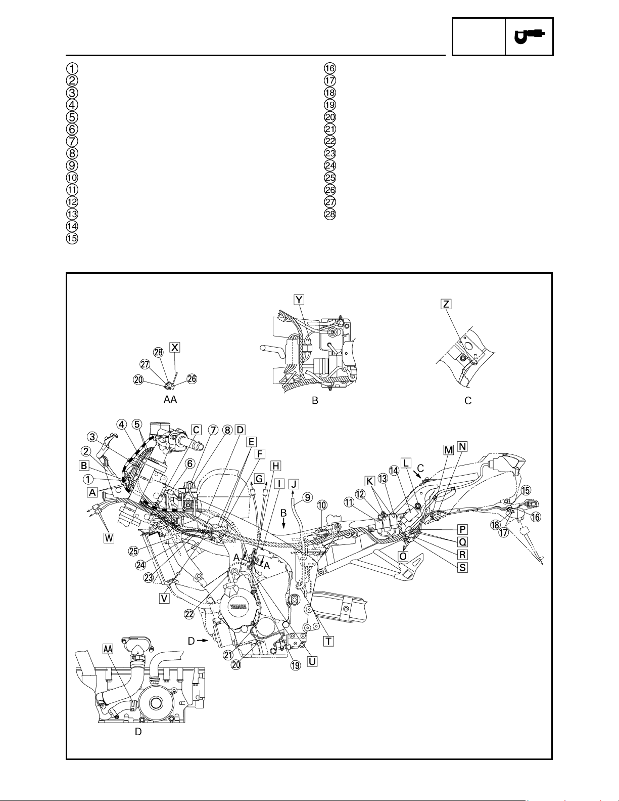
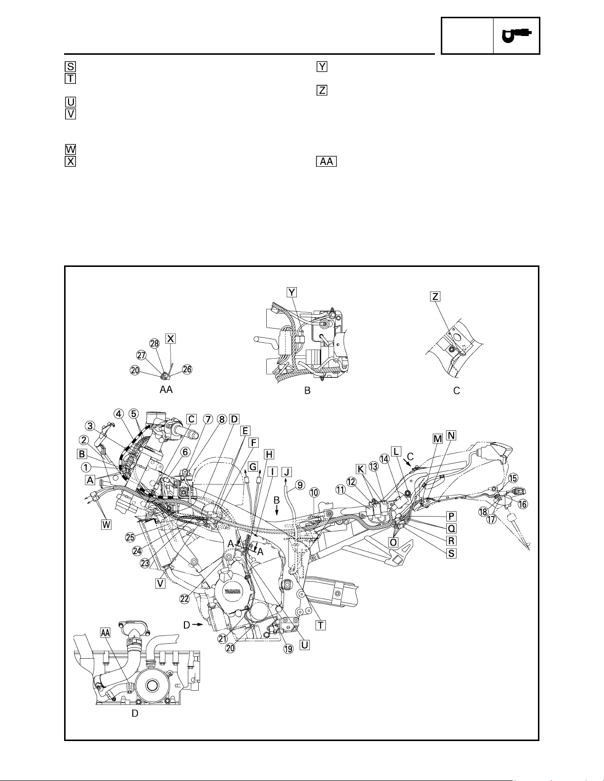
Main switch lead
Stay assembly
Left handlebar switch lead
Clutch cable
Throttle cables
Battery negative lead coupler
Starter relay lead
Battery negative lead
Fuel tank drain hose
Rectifier/regulator
Turn signal relay
Radiator fan motor relay
Dimmer relay
Starting circuit cut-off relay
Clamp
License plate light lead
Rear turn signal light lead (right)
Rear turn signal light lead (left)
Speed sensor lead
Sidestand switch lead
Oil level switch lead
A.C. magneto lead
Throttle cable (return side)
Throttle cable (pull side)
Radiator fan motor lead
Oil level gauge lead
A. C. magneto lead
Speed sensor lead
CABLE ROUTING
SPEC
6
Route the throttle cables above the stay assy 1.
Route the main switch lead above the clutch
cable.
Line up the left handlebar switch lead coupler
and fan motor lead coupler behind the head
pipe.
Route the clutch cable over the wire harness.
To the main switch.
Place three couplers on the flange of the cover.
To the fuel pump.
Clamp four wire leads. There should be no
excessive slack on the wire leads.
To the engine.
To the fuel tank.
Either installation position can be accepted, but
make sure that the leads are not crossed.
Clamp the rear turn signal light lead and license
plate light lead to the frame. Hook the clamp to
the bracket. Pull out the lead sufficiently to the
frame side and route it along with the side of the
back stay. Cut the tip of the clamp to be between
1 and 5 mm (0.04 and 0.20 in) upward.
Clamp the rear turn signal light lead and license
plate light lead to the frame. Cut the tip of the
clamp to be between 1 and 5 mm (0.04 and 0.20
in).
Gap between the lead and muffler should be 10
mm (0.39 in) or more.
Coupler should not run on the relay assembly.
To the tail/brake light.
To the license plate light.
To the rear turn signal light. (right)
CABLE ROUTING
SPEC
7
To the rear turn signal light (left)
Pass the fuel tank drain hose through the clamp
located under the coolant reservoir tank.
Route it behind the starter motor lead.
Point the bend-R section of the throttle cable
(pull side) to the inner side horizontally. It is also
possible to visually check the bend-R section.
To the headlight lead.
Point the tip of the clamp to the inner side of the
vehicle body.
Make sure to pass the neutral switch lead
through the hole of the flap.
Clamp the seat lock wire to the frame as shown
in the illustration. Secure the clamp to the weld
of the cross member with the frame. Position the
binding section in front of the vehicle body and
cut the tip to be between 1 and 5 mm (0.04 and
0.20 in).
Install the clamp with its ends facing between
the downward or forward position.
CABLE ROUTING
SPEC
8
Right handlebar switch lead
Throttle cables
Battery positive lead
Coolant reservoir tank hose
Battery cover
Connecter cover
Fuel tank breather hose
Brake fluid reservoir hose
Lean angle cut-off switch
Fuse box
Rear turn signal light lead (right)
License plate light lead
Rear turn signal light lead (left)
Seat lock cable
Rectifier/regulator
E.C.U
Fuel tank drain hose
Cover
Starter relay lead
Battery negative lead
Battery negative lead coupler
Clutch cable
Connecter cover
Cover 2
Spark plug lead
Air cut-off valve hose
CABLE ROUTING
SPEC
9
Either right or left side arrangement for the left
handlebar switch lead coupler and radiator fan
motor coupler can be accepted.
Point the L-shape terminal to the front side of
the vehicle.
Hook the starter motor lead to the alternate
pawls on the battery cover.
Route the crankshaft position sensor lead above
the starter motor leads.
To the crankshaft position sensor.
Clamp the starter motor lead and crankshaft
position sensor lead. Point the projected part of
the tip to the inner side of the vehicle.
Pass the radiator hose, coolant reservoir hose,
wire harness and starter motor lead in order
through the lower side of the vehicle.
Set the 4-pin coupler in the connector cover
after wiring it.
To the sidestand switch.
To the speed sensor.
To the A.C. magneto.
To the oil level switch.
To the tail/brake light switch.
To the neutral switch.
Push the wire harness in the groove of the mud
guard.
Point the opening section of the clamp upward.
To the rear turn signal (right)
To the rear turn signal (left)
To the license plate light.
To the tail/brake light.
CABLE ROUTING
SPEC
10
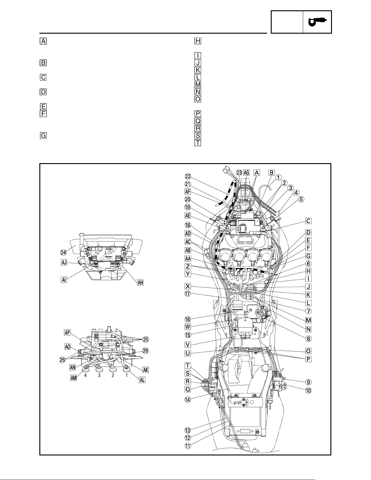
Point the tip of the clamp to the outside of the
vehicle.
Insert the enwinding clamp of the wire harness
into the hole of the rear frame.
Attach the rectifier/regulator lead to the clamp of
the rectifier bracket.
To the engine ground.
To the fuel injection.
To the fuel pump.
Route the clutch cable under the fuel injection
lead.
Pass the clutch cables through the clamp, and
then install the clamp to the cover. Position of
the clamp is forward of the cable stopper.
To the main switch.
Plate the adjuster of the clutch cable above
the cover.
Route the starter relay lead outside of the
main switch.
Press the battery negative lead into the space
between the ribs of the frame.
After connecting the coupler of the connector
cover position it inside.
Pass the spark plug leads #1 and #4 through
the slit of the cover 2.
Pass the spark plug lead #2 through the inner
hole of the cover 2.
Pass the spark plug lead #3 through the outer
hole of the cover 2.
Route the spark plug lead #4 behind the air
cut-off valve hose.
CABLE ROUTING
SPEC
11
Point the spark plug caps of #1 to #4 to the
direc-tion as shown in the illustration.
Route the spark plug lead #3 under the air
cut-off valve hose.
Route the spark plug lead #2 behind the air
cut-off valve hose.
Route the spark plug lead #4 by the front side
of the spark plug leads #2 and #3.
Route the spark plug leads #2 and #3 behind
the air cut-off valve hose.
CABLE ROUTING
SPEC
12
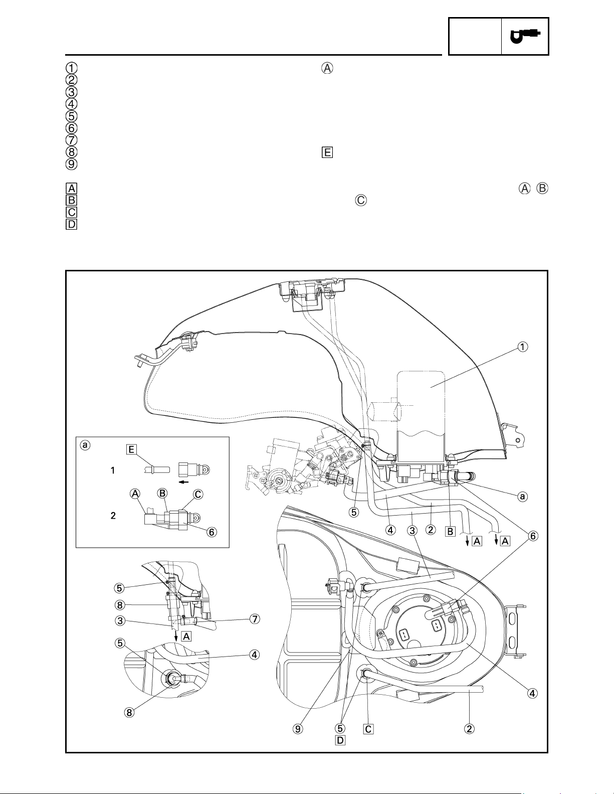
Fuel pump assembly
Fuel tank breather hose (except for CAL)
Fuel tank drain hose
Fuel hose
Clip
Clamp
Charge hose (for CAL)
Roll over valve (for CAL)
Fuel tank protector
Air opening.
Install the O-ring with its lip pointed upward.
Fuel tank breather hose has a white point mark.
Point the knob of clip front side.
Fuel piping connector attachment directions.
(fuel pump side)
1. It is inserted until it makes a click sound the con-
nector, and it checks that a connector does not
fail out. It takes care that a foreign substance
does not enter into a seal portion. (Working
gloves should not be used at the time of work.)
It prevents that this portion falls out.
2. The clamp is attached from the bottom after the
work of “1”.
It checks being completely equipped with ,
and section.
CABLE ROUTING
SPEC
13
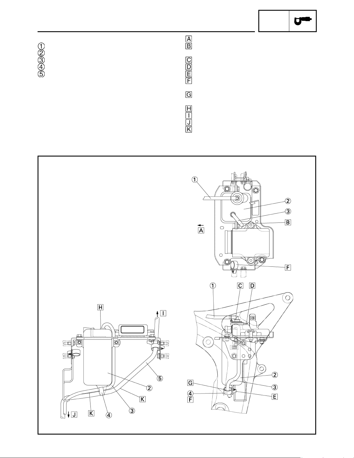
except for CAL
Coolant breather hose
Coolant reservoir tank
Coolant reservoir tank hose
Clamp
Fuel tank drain hose
Front side.
Pass the coolant reservoir tank hose hangs
down downward from back of the bolt.
Insert this portion securely.
Spittle is turned back.
Insert the clamp certainly.
It may open and close to direction of which. All
notches gear at the time of attachment.
Pass the coolant reservoir tank hose inside of
the clamp.
Insert in certainly.
To the fuel tank drain tube.
Air opening.
There should be no slacking of the hose when it
is routed.
CABLE ROUTING

CHAS
14
EAS00709
CHASSIS
SWINGARM AND DRIVE CHAIN
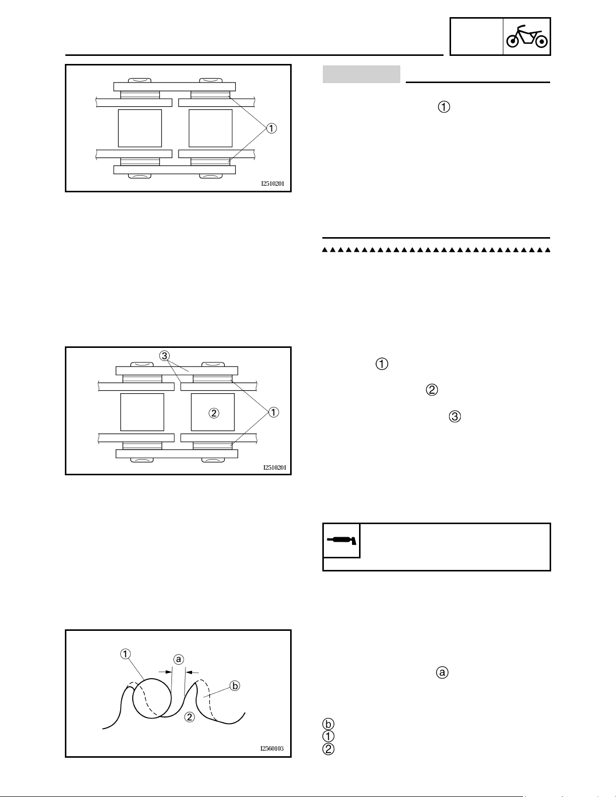
CHECKING THE DRIVE CHAIN
1. Measure:
• Measure the dimension between 15-links
on the inner side and outer side of the
roller and calculate the dimension between
pin centers.
• Dimension between pin centers = (Inner
dimension + Outer dimension )/2
• 15-link section of the drive chain
Out of specification → Replace the drive
chain, front drive sprocket and rear drive
sprocket as a set.
N
O
TE:N
O
TE:
• While measuring the 15-link section, push
down on the drive chain to increase its ten-
sion.
• Perform this measurement at two or three dif-
ferent places.
2. Check:
• drive chain
Stiffness → Clean and lubricate or replace.
3. Clean:
• drive chain
a. Wipe the drive chain with a clean cloth.
b. Put the drive chain in kerosene and remove
any remaining dirt.
c. Remove the drive chain from the kerosene
and completely dry it.
15-link drive chain section limit
(maximum)
239.3 mm (9.42 in)
SWINGARM AND DRIVE CHAIN
CHAS
15
CAUTION:
This motorcycle has a drive chain with
small rubber O-rings between the drive
chain side plates. Never use high-pressure
water or air, steam, gasoline, certain sol-
vents (e.g., benzine), or a coarse brush to
clean the drive chain. High-pressure meth-
ods could force dirt or water into the drive
chain's internals, and solvents will deterio-
rate the O-rings. A coarse brush can also
damage the O-rings. Therefore, use only
kerosine to clean the drive chain.
4. Check:
•O-rings
Damage → Replace the drive chain.
• drive chain rollers
Damage/ wear → Replace the drive chain.
• drive chain side plates
Damage/ wear → Replace the drive chain.
Cracks → Replace the drive chain and
make sure that the battery breather hose is
properly routed away from the drive chain
and below the swingarm.
5. Lubricate:
• drive chain
6. Check:
• drive sprocket
• rear wheel sprocket
More than 1 / 4 tooth wear → Replace the
drive chain sprockets as a set.
Bent teeth → Replace the drive chain
sprockets as a set.
Correct
Drive chain roller
Drive chain sprocket
Recommended lubricant
Engine oil or chain lubricant
suitable for O-ring chains
SWINGARM AND DRIVE CHAIN
ENG
16
EAS00192
ENGINE
ENGINE
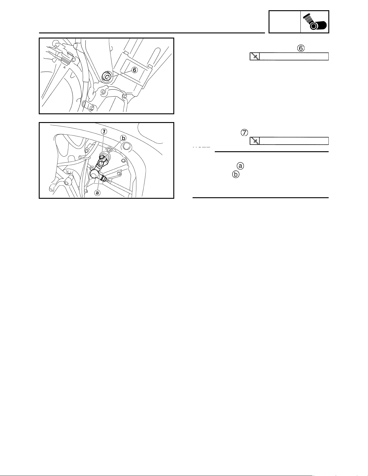
INSTALLING THE ENGINE
1. Install:
• rear engine mounting bolts
N
O
TE:N
O
TE:
Lubricate the rear engine mounting bolt
threads with lithium-soap-based grease.
2. Install:
• right front engine mounting bolt
• left front engine mounting bolts
N
O
TE:N
O
TE:
Do not fully tighten the bolts.
3. Tighten:
• self-locking nut
N
O
TE:N
O
TE:
First tighten the lower self-locking nut.
4. Tighten
• left front engine mounting bolts
55 Nm (5.5 m•kg, 40 ft•lb)
55 Nm (5.5 m•kg, 40 ft•lb)
ENGINE
ENG
17
5. Tighten
• right front engine mounting bolts
6. Install:
• shift arm bolt
N
O
TE:N
O
TE:
• Before installing, make sure to align the
punch mark of the shift shaft with the
punch mark of the shift arm.
• Align the bottom edge of the shift pedal with
the mark on the frame-to-swingarm bracket.
55 Nm (5.5 m•kg, 40 ft•lb)
10 Nm (1.0 m•kg, 7.2 ft•lb)
ENGINE
ENG
18
EAS00252
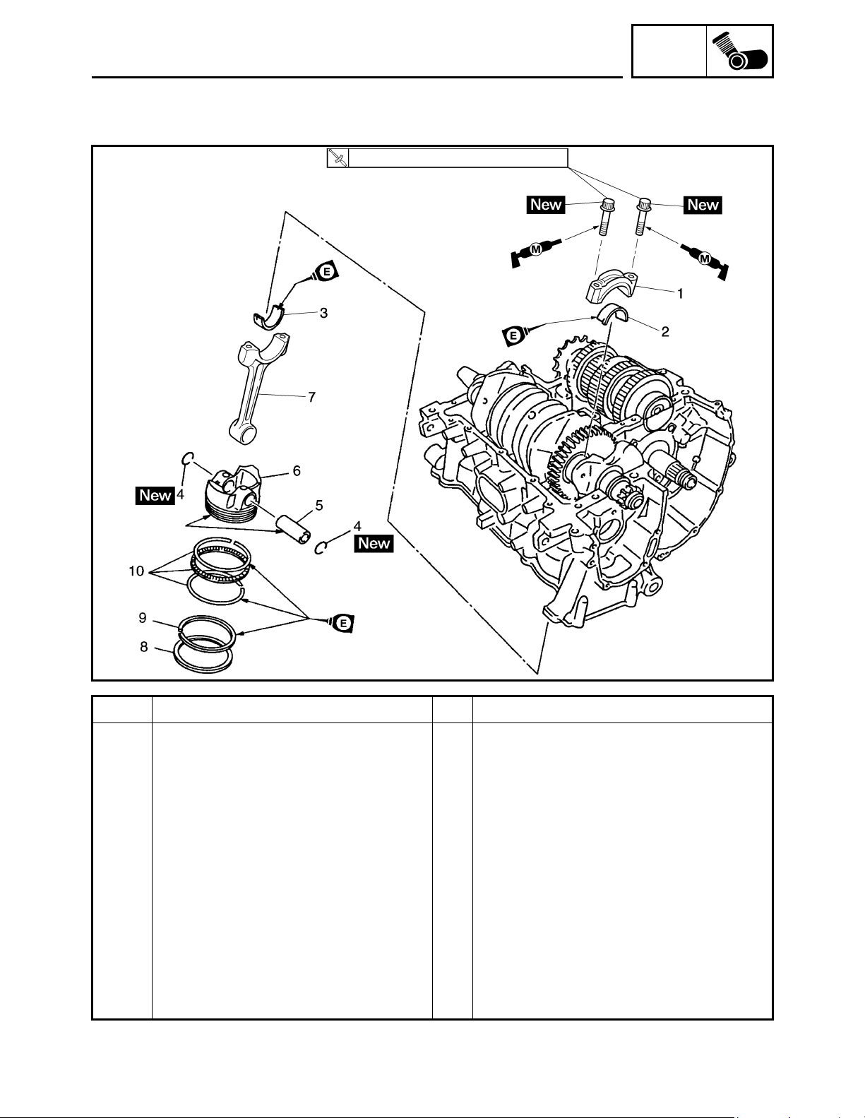
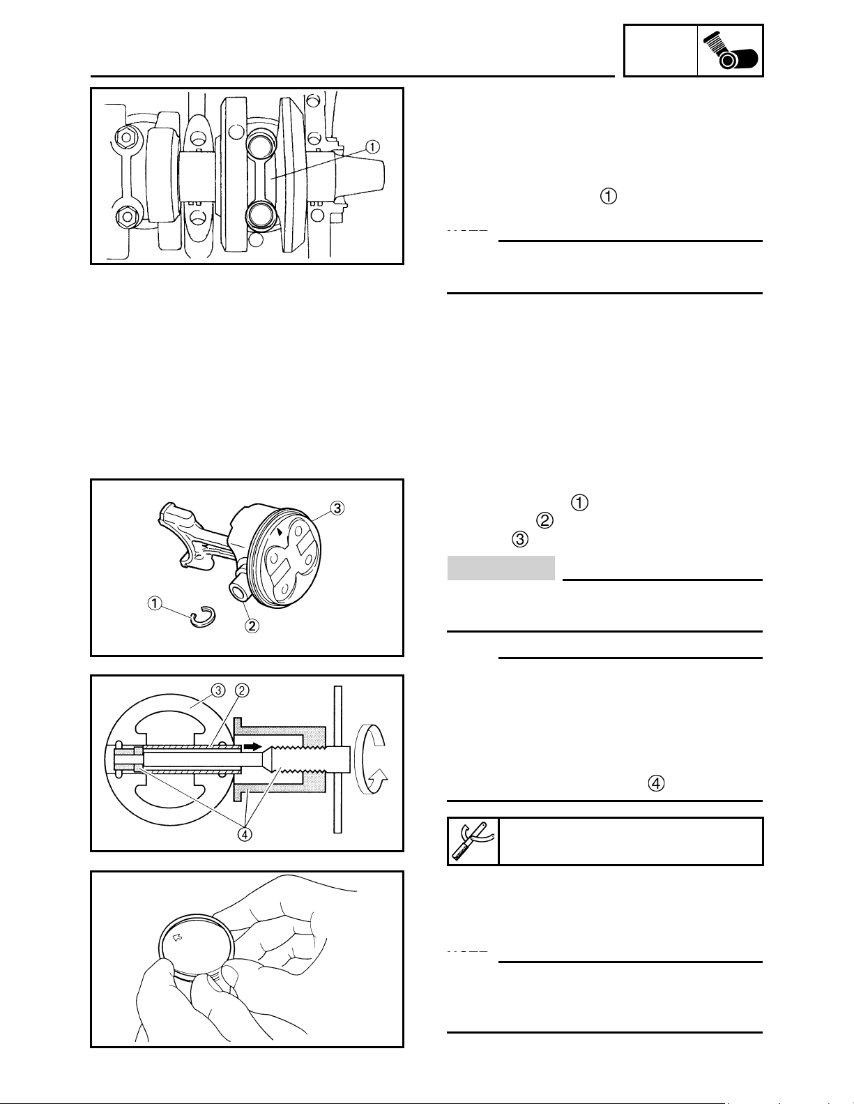
CONNECTING RODS AND PISTONS
Order Job / Part Q'ty Remar ks
Removing the connecting rods and
pistons
Remove the parts in the order listed.
Lower crankcase Refer to “CRANKCASE”.
1 Connecting rod cap 4
2 Big end lower bearing 4
3 Big end upper bearing 4
4 Piston pin clip 8
5 Piston pin 4
6Piston 4
7 Connecting rod 4
8 Top ring 4
92nd ring 4
10 Oil ring 4
For installation, reverse the removal
procedure.
15Nm (1.5 m•kg, 11ft•lb) + 120°
CONNECTING RODS AND PISTONS
ENG
19
EAS00393
REMOVING THE CONNECTING RODS AND
PISTONS
The following procedure applies to all of the
connecting rods and pistons.
1. Remove:
• connecting rod cap
• big end bearings
N
O
TE:N
O
TE:
Identify the position of each big end bearing so
that it can be reinstalled in its original place.
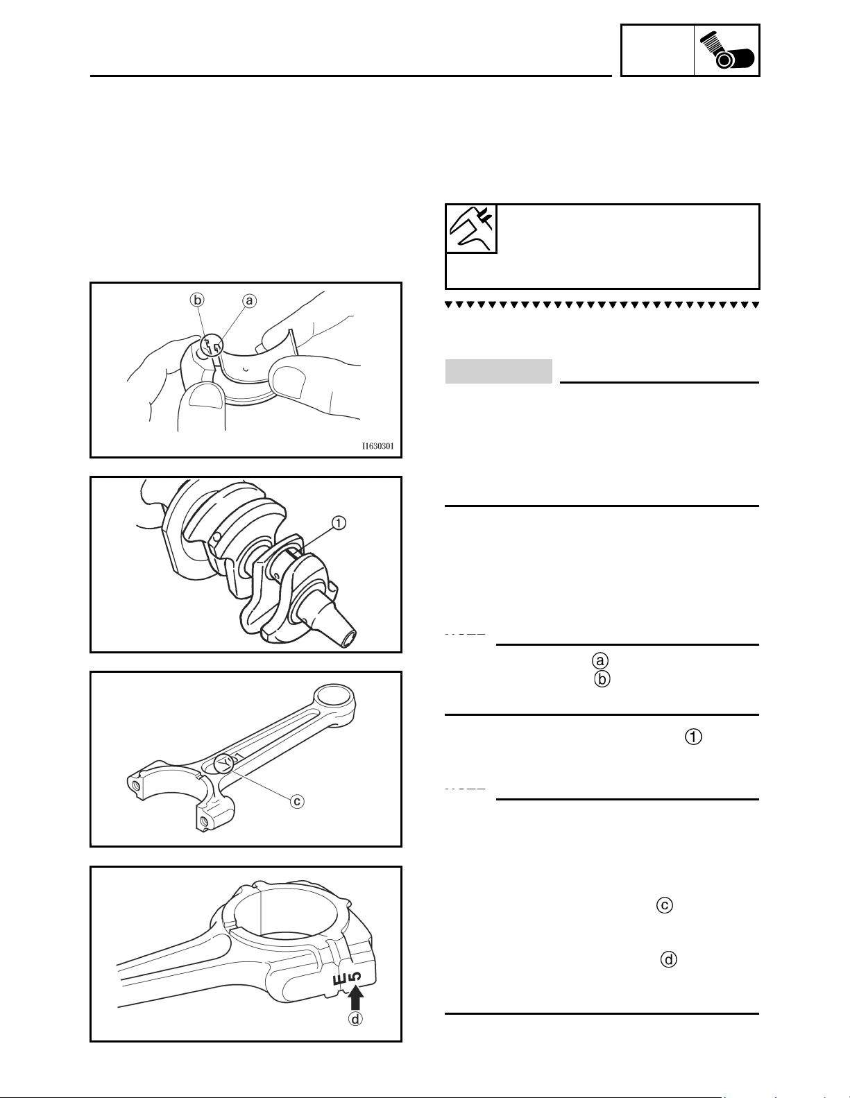
2. Remove:
• piston pin clips
• piston pin
•piston
CAUTION:
Do not use a hammer to drive the piston
pin out.
N
O
TE:N
O
TE:
• For reference during installation, put identifi-
cation marks on the piston crown.
• Before removing the piston pin, deburr the
piston pin clip groove and the piston pin bore
area. If both areas are deburred and the pis-
ton pin is still difficult to remove, remove it
with the piston pin puller set .
3. Remove:
• top ring
•2nd ring
•oil ring
N
O
TE:N
O
TE:
When removing a piston ring, open the end
gap with your fingers and lift the other side of
the ring over the piston crown.
Piston pin puller set
90890-01304, YU-01304
CONNECTING RODS AND PISTONS
ENG
20
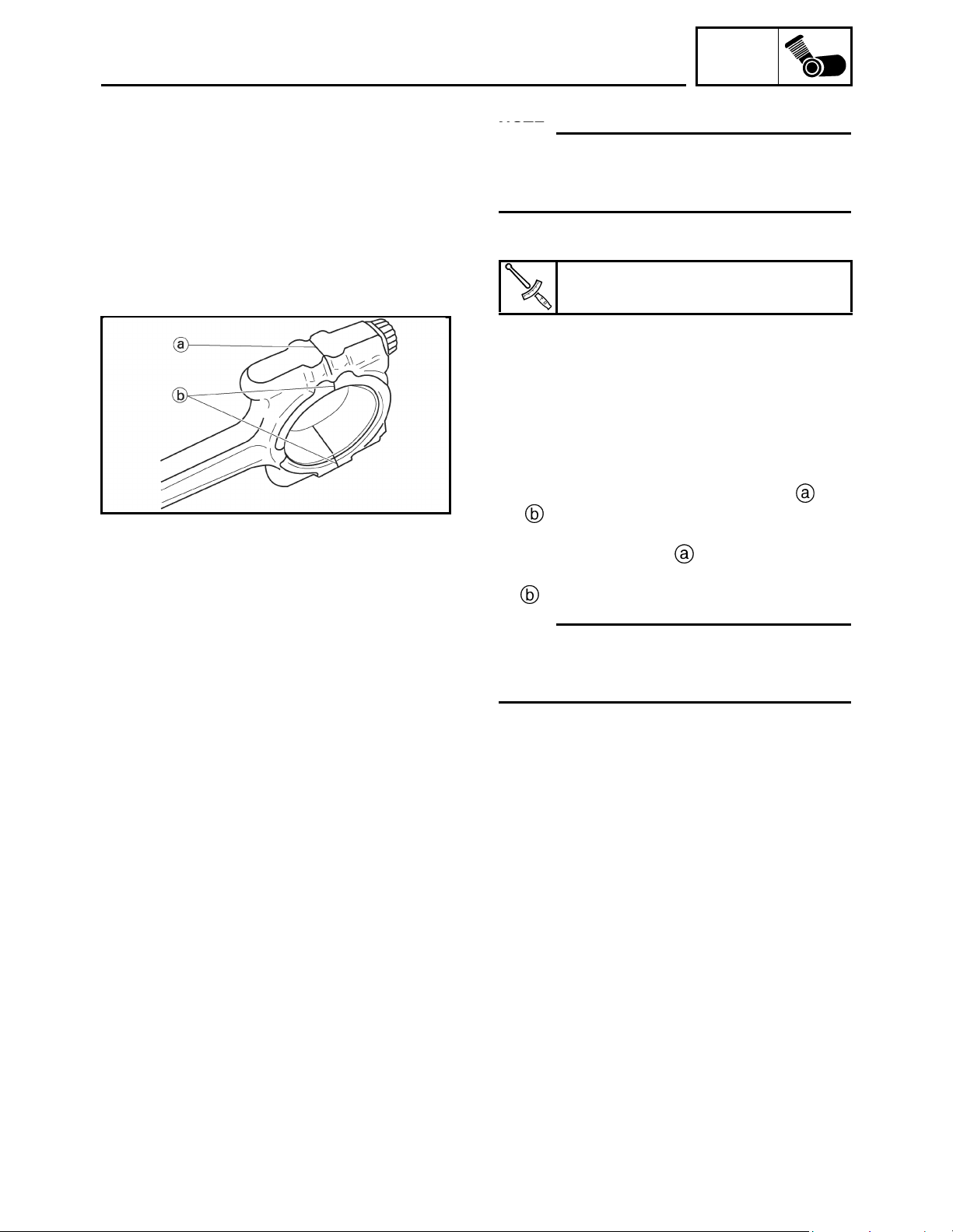
CHECKING THE BIG END BEARINGS
1. Measure:
• crankshaft-pin-to-big-end-bearing clear-
ance
Out of specification → Replace the big end
bearings.
The following procedure applies to all of the
connecting rods.
CAUTION:
Do not interchange the big end bearings
and connecting rods. To obtain the correct
crankshaft-pin-to-big-end-bearing clear-
ance and prevent engine damage, the big
end bearings must be installed in their orig-
inal positions.
a. Clean the big end bearings, crankshaft
pins, and the inside of the connecting rod
halves.
b. Install the big end upper bearing into the
connecting rod and the big end lower bear-
ing into the connecting rod cap.
N
O
TE:N
O
TE:
Align the projections on the big end bear-
ings with the notches in the connecting rod
and connecting rod cap.
c. Put a piece of Plastigauge
®
on the
crankshaft pin.
d. Assemble the connecting rod halves.
N
O
TE:N
O
TE:
• Do not move the connecting rod or crankshaft
until the clearance measurement has been
completed.
• Lubricate the bolt threads and seats with
molybdenum disulfide grease.
• Make sure that the “Y” mark on the con-
necting rod faces towards the left side of the
crankshaft.
• Make sure that the characters on both the
connecting rod and connecting rod cap are
aligned.
Crankshaft-pin-to-big-end-bearing
clearance
0.028 ~ 0.052 mm
(0.0011 ~ 0.0020 in)
CONNECTING RODS AND PISTONS
ENG
21
e. Tighten the connecting rod bolts.
N
O
TE:N
O
TE:
Install by carrying out the following procedures
in order to assemble in the most suitable con-
dition.
• connecting rod bolts
f. Replace the connecting rod bolts with new
ones.
g. Clean the connecting rod bolts.
h. After installing the big end bearing, assem-
ble the connecting rod and connecting rod
cap once using a single unit of the connect-
ing rod.
i. Tighten the connecting rod bolt while
checking that the sections shown and
are flush with each other by touching
the surface.
• Side machined face
• Thrusting faces (4 places at front and rear)
N
O
TE:N
O
TE:
To install the big end bearing, care should be
taken not to install it at an angle and the posi-
tion should not be out of alignment.
j. Loosen the connecting rod bolt, remove the
connecting rod and connecting rod cap and
install these parts to the crankshaft with the
big end bearing kept in the current condi-
tion.
Connecting rod bolt
24.5 Nm (2.5 m•kg, 17.7 ft•lb)
CONNECTING RODS AND PISTONS
ENG
22
k. Tighten the connecting rod bolts.
CAUTION:
Tighten the connecting rod bolts using the
plastic-region tightening angle method.
Always install new bolts.
l. Clean the connecting rod bolts.
m. Tighten the connecting rod bolts.
n. Put a mark on the corner of the connect-
ing rod bolt and the connecting rod cap
o. Tighten the bolt further to reach the speci-
fied angle (120°).
p. After the installation, check that the section
show is flush with each other by touch-
ing the surface.
• Side machined face
WARNING
• When the bolt is tightened more than the
specified angle, do not loosen the bolt and
then retighten it.
Replace the bolt with a new one and per-
form the procedure again.
• If they are not flush with each other,
remove the connecting rod bolt and big
end bearing and restart from step "e". In
this case, make sure to replace the con-
necting rod bolt.
CAUTION:
• Do not use a torque wrench to tighten the
nut to the specified angle.
• Tighten the bolt until it is at the specified
angles.
Connecting rod bolt
15 Nm (1.5 m•kg, 11 ft•lb) + 120°
CONNECTING RODS AND PISTONS
ENG
23
q. Remove the connecting rod and big end
bearings.
Refer to "REMOVING THE CONNECTING
RODS AND PISTONS".
r. Measure the compressed Plastigauge
®
width on the crankshaft pin.
If the crankshaft-pin-to-big-end-bearing
clearance is out of specification, select
replacement big end bearings.
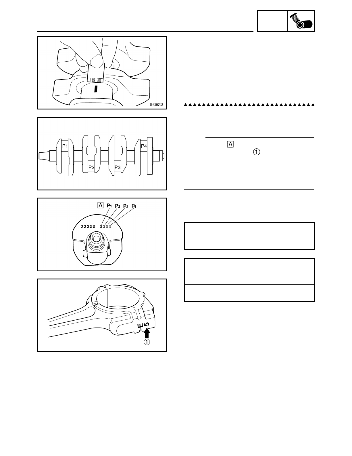
2. Select:
• big end bearings (P1 ~ P4)
N
O
TE:N
O
TE:
• The numbers stamped into the crankshaft
web and the numbers on the connecting
rods are used to determine the replacement
big end bearing sizes.
• “P1” ~ “P4” refer to the bearings shown in the
crankshaft illustration.
For example, if the connecting rod “P
1
” and the
crankshaft web “P
1
” numbers are “5” and "2"
respectively, then the bearing size for “P
1
” is:
“P
1
” (connecting rod) – “P
1
”
(crankshaft) =
5 – 2 = 3 (brown)
BIG END BEARING COLOR CODE
1Blue
2Black
3Brown
4 Green
CONNECTING RODS AND PISTONS
ENG
24
INSTALLING THE CONNECTING ROD AND
PISTON
The following procedure applies to all of the
connecting rods and pistons.
1. Install:
• top ring
• 2nd ring
• upper oil ring rail
• oil ring expander
• lower oil ring rail
N
O
TE:N
O
TE:
Be sure to install the piston rings so that the
manufacturer's marks or numbers face up.
2. Install:
•piston
(onto the respective connecting rod )
• piston pin
• piston pin clip
N
O
TE:N
O
TE:
• Apply engine oil onto the piston pin.
• Make sure that the “Y” mark on the con-
necting rod faces left when the arrow mark
on the piston is pointing up. Refer to the illus-
tration.
• Reinstall each piston into its original cylinder
(numbering order starting from the left: #1 to
#4).
3. Lubricate:
•piston
• piston rings
• cylinder
(with the recommended lubricant)
Recommended lubricant
Engine oil
CONNECTING RODS AND PISTONS
Loading...