


Model No. WEEMSY18220
Serial No.
Write the serial number in the space above for future reference.
Serial Number Decal (Under Seat)
QUESTIONS?
As a manufacturer, we are committed to providing complete customer satisfaction. If you have questions, or if there are missing parts, please call:
08457 089 009
Or write:
ICON Health & Fitness, Ltd. Unit 4
Revie Road Industrial Estate Revie Road
Beeston
Leeds, LS118JG UK
email: csuk@iconeurope.com
 CAUTION
Read all precautions and instructions in this manual before using this equipment. Save this manual for future reference.
USER'S MANUAL


 Visit our website at www.iconeurope.com

TABLE OF CONTENTS
IMPORTANT PRECAUTIONS . . . . . . . . . . . . . . . . . . . . . . . . . . . . . . . . . . . . . . . . . . . . . . . . . . . . . . . . . . . . . . . . 3 BEFORE YOU BEGIN . . . . . . . . . . . . . . . . . . . . . . . . . . . . . . . . . . . . . . . . . . . . . . . . . . . . . . . . . . . . . . . . . . . . . . 4 ASSEMBLY . . . . . . . . . . . . . . . . . . . . . . . . . . . . . . . . . . . . . . . . . . . . . . . . . . . . . . . . . . . . . . . . . . . . . . . . . . . . . . 5 ADJUSTMENTS . . . . . . . . . . . . . . . . . . . . . . . . . . . . . . . . . . . . . . . . . . . . . . . . . . . . . . . . . . . . . . . . . . . . . . . . . . 15 WEIGHT RESISTANCE CHART . . . . . . . . . . . . . . . . . . . . . . . . . . . . . . . . . . . . . . . . . . . . . . . . . . . . . . . . . . . . . .16 CABLE DIAGRAM . . . . . . . . . . . . . . . . . . . . . . . . . . . . . . . . . . . . . . . . . . . . . . . . . . . . . . . . . . . . . . . . . . . . . . . . .17 TROUBLESHOOTING AND MAINTENANCE . . . . . . . . . . . . . . . . . . . . . . . . . . . . . . . . . . . . . . . . . . . . . . . . . . .18 ORDERING REPLACEMENT PARTS . . . . . . . . . . . . . . . . . . . . . . . . . . . . . . . . . . . . . . . . . . . . . . . . . .Back Cover
Note: A PART IDENTIFICATION CHART and a PART LIST/EXPLODED DRAWING are attached in the centre of this manual. Remove the PART IDENTIFICATION CHART and the PART LIST/EXPLODED DRAWING before beginning assembly.
WEIDER is a registered trademark of ICON Health & Fitness, Inc.
2
IMPORTANT PRECAUTIONS
 WARNING: To reduce the risk of serious injury, read the following important precautions before using the weight system.
1.Read all instructions in this manual and in the accompanying literature before using the weight system. Use the weight system only as described in this manual.
2.It is the responsibility of the owner to ensure that all users of the weight system are adequately informed of all precautions.
3.The weight system is intended for home use only. Do not use the weight system in a commercial, rental, or institutional setting.
4.Use the weight system only on a level surface. Cover the floor or carpet beneath the weight system to protect the floor.
5.Make sure all parts are properly tightened each time the weight system is used. Replace any worn parts immediately.
6.Keep children under the age of 12 and pets away from the weight system at all times.
7.Keep hands and feet away from moving parts.
8.Always wear athletic shoes for foot protection when using the weight system.
9.The weight system is designed to support a maximum user weight of 135 kg (300 lbs).
10.Always stand on the foot plate when performing an exercise that could cause the weight system to tip.
11.Never release the arms, leg lever, or lat bar whilst weights are raised; the weights will fall with great force.
12.Make sure that the cables remain on the pulleys at all times. If the cables bind whilst you are exercising, stop immediately and make sure that the cables are on all of the pulleys.
13.Always disconnect the lat bar from the weight system when performing an exercise that does not use the lat bar.
14.If you feel pain or dizziness at any time whilst exercising, stop immediately and begin cooling down.
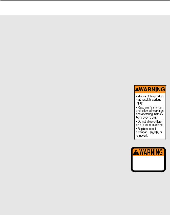
15.The warning decals
shown here have been placed on the weight
system in the locations shown on page
4. If a decal is missing or illegible, please call our Customer Service Department toll-free at 08457 089 009 to order a free replacement
decal. Place the decal on the weight system
in the location shown.
Decal 1
Keep hands and fingers clear of this area.
Decal 2
 WARNING: Before beginning this or any exercise program, consult your physician. This is especially important for persons over the age of 35 or persons with pre-existing health problems. Read all instructions before using. ICON assumes no responsibility for personal injury or property damage sustained by or through the use of this product.
3
BEFORE YOU BEGIN
Thank you for selecting the versatile WEIDER® 8950 weight system. The WEIDER® 8950 weight system offers a selection of weight stations designed to develop every major muscle group of the body. Whether your goal is to tone your body, build dramatic muscle size and strength, or improve your cardiovascular system, the WEIDER® 8950 weight system will help you to achieve the results you want.
For your benefit, read this manual carefully before using the weight system. If you have additional
questions, please call our Customer Service Department at 08457 089 009. To help us assist you, please note the product model number and serial number before calling. The model number is WEEMSY18220. The serial number can be found on a decal attached to the weight system (see the front cover of this manual for the location of the decal).
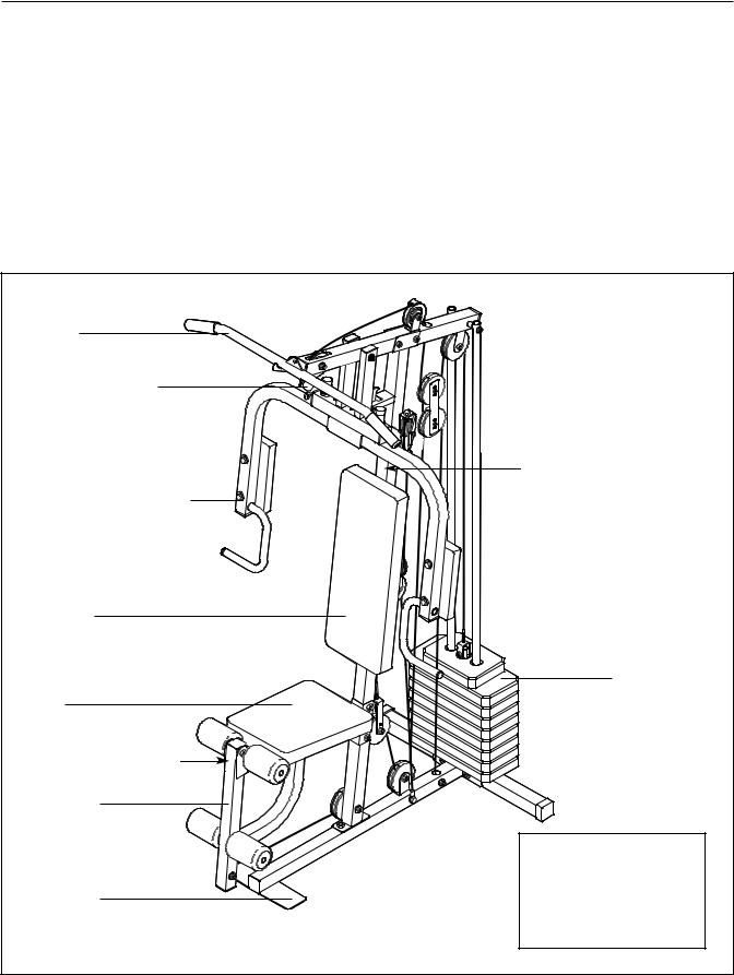
Before reading further, please review the drawing below and familiarise yourself with the parts that are labelled.
Lat Bar |
|
|
High Pulley Station |
|
|
|
Warning Decal 1 |
|
Butterfly Arm/Press Arm |
|
|
Backrest |
|
|
|
Weight Stack |
|
Seat |
|
|
Warning Decal 2 |
|
|
Leg Lever |
|
|
|
ASSEMBLED |
|
|
DIMENSIONS: |
|
Foot Plate |
Height: 200 cm (79 in.) |
|
Width: 93 cm (36.6 in.) |
||
|
||
|
Length: 119 cm (47 in.) |
|
|
4 |
ASSEMBLY
Make Things Easier for Yourself
Everything in this manual is designed to ensure that the weight system can be assembled successfully by anyone. However, it is important to realise that the versatile weight system has many parts and that the assembly process will take time. Most people find that by setting aside plenty of time, assembly will go smoothly.
Before beginning assembly, carefully read the following information and instructions:
•Assembly requires two people.
•Place all parts in a cleared area and remove the packing materials. Do not dispose of the packing materials until assembly is completed.
•Tighten all parts as you assemble them, unless instructed to do otherwise.
•As you assemble the weight system, make sure all parts are oriented as shown in the drawings.
•For help identifying small parts, use the PART IDENTIFICATION CHART.
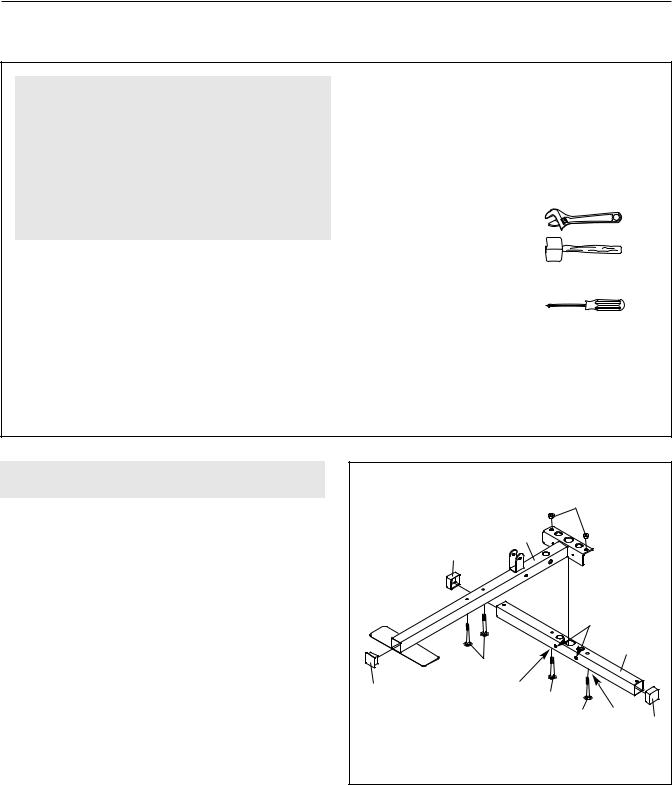
The following tools (not included) are required for assembly:
• two adjustable spanners
• one rubber mallet
• one standard screwdriver 
• one Phillips screwdriver
•lubricant, such as grease or petroleum jelly, and soapy water.
Assembly will be more convenient if you have a socket set, a set of open-end or closed-end spanners, or a set of ratchet spanners.
FRAME ASSEMBLY |
1 |
|
|
|
|
|
|
|
|
68 |
|
1. Before beginning assembly, be sure that you |
|
1 |
|
have read and understand the information in |
|
|
|
the box above. |
|
41 |
|
Press a 50mm Square Inner Cap (26) into the end |
|
These holes |
|
|
|
are smaller |
|
of the Base (1). Press two 50mm Square Outer |
|
|
than on the |
Caps (41) onto the ends of the Stabiliser (2). |
|
opposite side. |
|
Orient the Stabiliser (2) with the indents around |
|
|
2 |
the holes on the bottom. Insert two M10 x 65mm |
|
58 |
|
Carriage Bolts (59) into the bottom of the |
26 |
Indent |
|
Stabiliser. Insert two M8 x 63mm Carriage Bolts |
|
||
59 |
|
||
|
Indent |
||
(58) into the bottom of the Base (1). Note: It may |
|
59 |
|
be helpful to place tape over the heads of the |
|
|
41 |
|
|
|
|
Carriage Bolts to hold them in place. |
|
|
|
Attach the Base (1) to the Stabiliser (2) with the |
|
|
|
M10 x 65mm Carriage Bolts (59) and two M10 |
|
|
|
Nylon Locknuts (68). Do not tighten the |
|
|
|
Locknuts yet. |
|
|
|
5

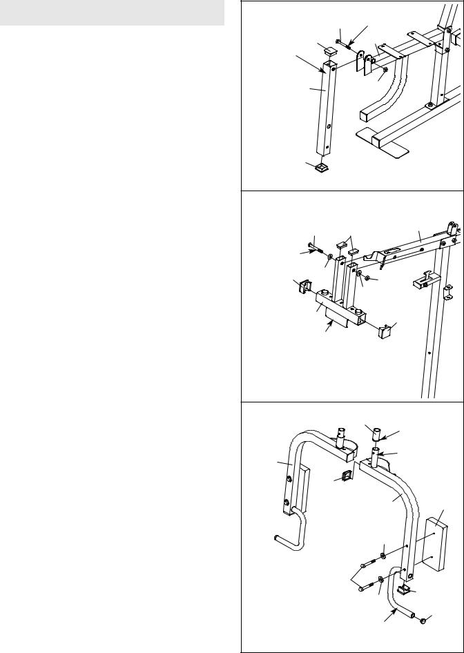
2.Attach the Upright (3) to the Base (1) with the two M8 x 63mm Carriage Bolts (58) and two M8 Nylon Locknuts (69). Do not tighten the
Locknuts yet.
Press a 25mm x 50mm Inner Cap (25) into the tube on the Upright (3). Attach the Press Frame Lock (39) to the Upright with an M8 x 63mm Bolt (66), two M8 Washers (71), and an M8 Nylon Locknut (69). Do not overtighten the Nylon
Locknut; the Press Frame Lock must be able to pivot easily.
3.Set two Weight Bumpers (17) over the indicated holes in the Stabiliser (2). Insert two Weight Guides (10) into the same holes. Secure the Weight Guides in place with two M10 x 70mm Bolts (57), two M10 Washers (70), two M10 x 12.5mm Spacers (37), and two M10 Nylon Locknuts (68).
Tighten the Nylon Locknuts (68, 69) used in steps 1 and 3.
2
39
66
71
69
25 
 71
71

 3
3
69
1
58
3
10
17 70 |
57 |
|
68 


 37
37
68 2
6
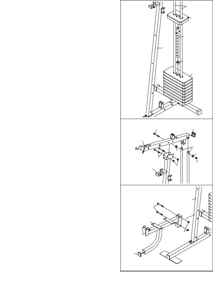
4.Slide the eight Weights (15) onto the Weight Guides (10), with the slot for the Weight Pin (not shown) on the bottom and on the side away from the Upright (3).
Insert the Weight Tube Bumper (13) into the bottom of the Weight Tube (12). Insert the Weight Tube into the Weights (15).
Slide the Top Weight (14) onto the Weight Guides (10).
5.Press a 50mm Square Inner Cap (26) into the Top Frame (4).
Attach the Top Frame (4) to the Upright (3) with two M8 x 68mm Bolts (63) and two M8 Nylon Locknuts (69). Do not tighten the Locknuts yet.
Attach the Top Frame (4) between the Weight Guides (10) with an M10 x 155mm Bolt (62), two M10 Washers (70), and an M10 Nylon Locknut (68).
Tighten the Nylon Locknuts (68, 69) used in steps 2 and 5.
6.Press a 45mm Square Inner Cap (24) into the end of the Seat Frame (8).
Attach the Seat Frame (8) to the Upright (3) with two M10 x 70mm Bolts (57) and two M10 Nylon Locknuts (68).
4 |
|
10 |
|
|
|
|
|
14 |
|
|
12 |
|
3 |
|
|
|
13 |
|
|
15 |
5 |
|
|
62 |
|
26 |
4 |
|
|
|
|
10 |
|
70 |
70 |
63 |
|
|
3 |
69 |
68 |
|
||
6 |
|
|
|
|
3 |
57 |
|
|
8 |
|
|
|
|
68 |
24 |
|
|
7
ARM ASSEMBLY
7.Press two 45mm Square Inner Caps (24) into the Leg Lever (9).
Lubricate an M10 x 73mm Bolt (74) with grease. Attach the Leg Lever (9) to the Seat Frame (8) with the Bolt and an M10 Nylon Locknut (68).
Make sure the warning decal is in the indicated position. Do not overtighten the Locknut; the Leg Lever must be able to pivot easily.
8.Press two 25mm x 50mm Inner Cap (25) into the top of the Press Frame (5). Press two 50mm Square Inner Caps (26) into the ends of the Press Frame.
Lubricate an M10 x 125mm Bolt (64) with grease. Orient the Press Frame (5) with the bracket on the side shown. Attach the Press Frame to the Top Frame (4) with the Bolt, two M10 Washers (70), and an M10 Nylon Locknuts (68). Do not overtighten the Locknut; the Press Frame must be able to pivot easily.
9.Press two 45mm Square Inner Caps (24) into the Left Arm (7). Press a 25mm Round Inner Cap
(23)into the handle. Lubricate the indicated post with grease. Slide a 38mm x 50mm Round Bushing (28) onto the post on the Arm; make sure that the lip on the Bushing is oriented as shown.
Attach an Arm Pad (20) to the Left Arm (7) with two M6 x 58mm Bolts (65) and two M6 Washers (73).
Repeat this step with the Right Arm (6).
7 |
|
|
|
|
|
|
74 |
Lubricate |
|
|
|
|
|
|
Warning |
24 |
|
8 |
|
|
|
|
|
|
Decal |
|
|
|
|
|
9 |
|
68 |
|
24 |
|
|
|
|
8 |
|
|
|
|
|
64 |
25 |
4 |
|
|
|
|||
Lubricate |
|
|
|
|
26 |
70 |
|
68 |
|
|
|
|
||
|
|
|
70 |
|
|
5 |
|
|
26 |
|
|
|
|
|
|
Bracket |
|
|
|
9 |
|
|
28 |
|
|
|
|
Lip |
|
|
|
|
|
|
6 |
|
|
|
Post |
|
|
|
|
|
|
24 |
|
|
|
|
|
|
7 |
20 |
|
|
|
73 |
|
|
|
65 |
|
|
|
|
|
73 |
24 |
|
|
|
|
|
|
|
|
|
23 |
|
|
|
Handle |
|
8
 Loading...