


Table of contents
Parts checklist |
1 |
Parts checklist for ia5865/ia5870 |
1 |
Parts checklist for ia5878/ia5884 |
2 |
Parts checklist for ia5882/ia5890 |
3 |
Installation |
4 |
Choose location |
4 |
Connect power and telephone line cords |
4 |
Install handset battery |
5 |
Wall mounting bracket installation |
6 |
Desk/table bracket installation |
6 |
If you subscribe to DSL service |
7 |
Belt clip |
7 |
Check for dial tone |
8 |
Charge the handset battery |
8 |
Language |
8 |
Set the dial mode |
8 |
Set handset date and time |
9 |
Handset ringer style |
9 |
Set ringer volume |
9 |
Telephone operation . . . . . . . . . . . . . . . . . . 10
Handset layout |
10 |
Telephone base layout |
11 |
Handset operation |
12 |
Telephone base operation |
14 |
Temporary tone dialing |
15 |
Call transfer |
15 |
Headset jack |
17 |
Operating range |
17 |
Directory |
18 |
Store a directory entry |
18 |
Chart of characters |
19 |
Edit a directory entry |
20 |
Delete a directory entry |
20 |
Move a directory entry into speed dial |
21 |
Dial a number from the directory |
21 |
Speed dial |
22 |
Store a speed dial entry |
22 |
Edit a speed dial entry |
23 |
Delete a speed dial entry |
24 |
Dial a speed dial number |
24 |
Reassign locations in speed dial |
24 |
Caller ID |
25 |
About call history (caller ID) |
26 |
Review call history |
26 |
Delete records from call history |
27 |
Dial a displayed number |
27 |
Store a call history record in the directory |
27 |
Display screen messages |
28 |
Answering system operation |
29 |
Audible indicators |
29 |
Setting the clock |
29 |
Record your announcement |
30 |
Review your announcement |
30 |
Delete your announcement |
31 |
Setup the answering system |
31 |
Listen to, save & delete messages |
33 |
Call screening/intercept |
33 |
Record a memo |
33 |
Answering system operation - remote access |
35 |
Accessing the answering system remotely |
35 |
www.vtechphones.com
Voice menu |
35 |
Remote access commands |
35 |
Display screen messages |
37 |
Battery information |
38 |
Battery care and performance |
38 |
Replacing the handset battery |
38 |
Troubleshooting |
39 |
Maintenance |
49 |
Limited Warranty |
49 |
Important safety instructions . . . . . . . . . . . . . . 51
FCC, ACTA and IC regulations |
52 |
The RBRC® seal |
53 |
Technical specifications |
54 |
Index |
55 |
www.vtechphones.com |
ii |
NEED HELP?
This user’s manual has all the feature operation and troubleshooting you will need to install and operate your new VTech phone. Please take the time to review thoroughly to ensure proper installation of this VTech innovative and feature rich product. You can also visit our website at www.vtechphones.com for support, shopping, and everything new at VTech.
In Canada, please visit www.vtechcanada.com
iii |
www.vtechphones.com |
Parts checklist
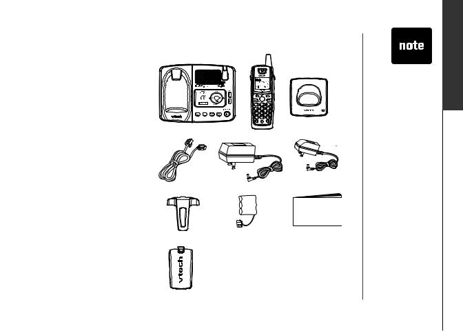
Parts checklist for ia5865/ia5870
•Telephone base with wall mounting/desktop bracket
•Handsets (2)
•Charger
•Telephone line cord
•Base power adapter
•Charger power adapter
•Belt clips (2)
•Batteries (2)
•User’s manual
To purchase replacement batteries, visit us on the web at www.vtechphones.com or call us at 1-800-595-9511. In Canada, go to www.vtechcanada.com or call us at 1-800-267-7377.
|
SELECT |
Telephone base with wall |
|
mounting/desktop bracket |
Handsets (2) |
Telephone line cord |
Base power adapter |
|
Belt clips (2) |
Batteries (2) |
Battery compartment covers (2)
www.vtechphones.com
• Important! Please read the
Important safety instructions on page 51 before using this telephone.
Charger
Charger power adapter
User’s manual
started Getting
Parts checklist
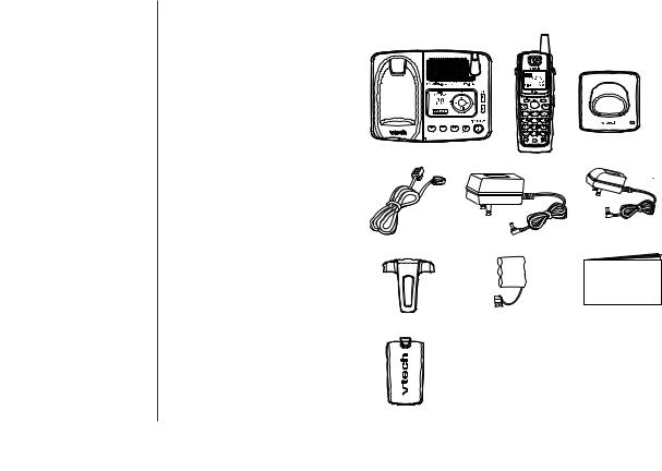
Parts checklist for ia5878/ia5884
•Telephone base with wall mounting/desktop bracket
•Handsets (3)
•Chargers (2)
•Telephone line cord
•Base power adapter
•Charger power adapters (2)
•Belt clips (3)
•Batteries (3)
•User’s manual
To purchase replacement batteries, visit us on the web at www.vtechphones.com or call us at 1-800-595-9511. In Canada, go to www.vtechcanada.com or call us at 1-800-267-7377.
|
SELECT |
Telephone base with wall |
Chargers (2) |
mounting/desktop bracket |
Handsets (3) |
|
Charger power adapters |
Telephone line cord |
Base power adapter (2) |
|
Belt clips (3) |
Batteries (3) |
User’s manual |
Battery compartment covers (3)
www.vtechphones.com
Parts checklist
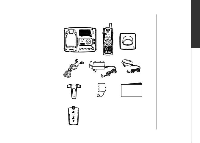
Parts checklist for ia5882/ia5890
•Telephone base with wall mounting/desktop bracket
•Handsets (4)
•Chargers (3)
•Telephone line cord
•Base power adapter
•Charger power adapters (3)
•Belt clips (4)
•Batteries (4)
•User’s manual
To purchase replacement batteries, visit us on the web at www.vtechphones.com or call us at 1-800-595-9511. In Canada, go to www.vtechcanada.com or call us at 1-800-267-7377.
|
SELECT |
Telephone base with wall |
Chargers (3) |
mounting/desktop bracket |
Handsets (4) |
Charger power adapters (3)
Telephone line cord |
Base power adapter |
|
Belt clips (4) |
Batteries (4) |
User’s manual |
Battery compartment covers (4)
www.vtechphones.com
started Getting
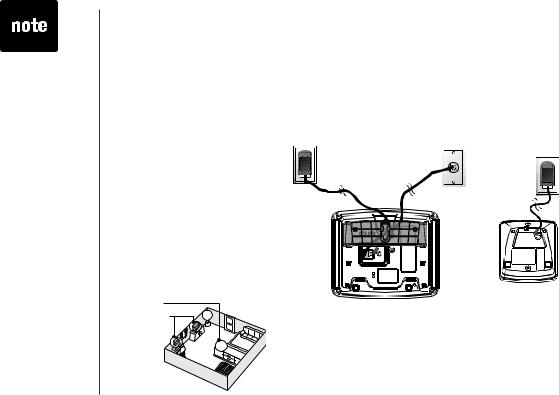
•Install the telephone base away from electronic equipment such as personal computers, television sets or microwave ovens. Avoid excessive heat, cold, dust or moisture.
•Connect the power and telephone line cords to the underside of the base as illustrated.
•Plug the base power adapter into an electrical outlet.
•Connect the telephone line cord to the wall jack.
•This power unit is intended to be
correctly orientated in a vertical or floor mount position.
The prongs are not designed to hold the plug in place if it is plugged into a ceiling or an under the table /cabinet outlet.
Installation
Choose location
For maximum performance of your cordless telephone system:
1.Choose a central location for your telephone base.
2.Install your telephone base and extension handset away from electronic equipment, such as personal computers, television sets and microwave ovens.
3.In locations where there are multiple cordless telephones, separate telephone bases as much as possible.
4.Install your telephone equipment away from heat sources and sunlight.
5.Avoid excessive moisture, dust or extreme cold.
1.
2.
Connect power and telephone line cords
Standard |
|
Modular |
electrical outlet |
|
|
|
telephone jack |
|
|
|
|
|
|
|
|
|
|
www.vtechphones.com
Installation
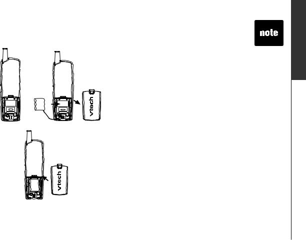
Install handset battery
a) Align the two holes in the plug with the socket |
• |
Use only the |
|
pins in the handset battery compartment, |
|||
|
provided VTech |
||
matching the red and black wires to the color- |
|
||
|
battery, or |
||
coded label. Snap the plug into place. Put the |
|
||
|
equivalent. |
||
battery into the compartment. |
|
||
|
To purchase |
||
|
|
||
b) Place the battery in the compartment with the |
|
replacement |
|
wires tucked inside. |
|
batteries, |
|
c) Place battery compartment cover by sliding |
|
visit us on the |
|
|
web at www. |
||
it upward until it clicks into place. |
|
||
|
vtechphones. |
||
|
|
||
d)The battery may have enough power for short |
|
com or call us |
|
calls. For best performance, put the handset in |
|
at 1-800-595- |
|
the telephone base and charge the battery for at |
|
9511. In |
|
least 16 hours. |
|
Canada,go |
|
|
|
to www. |
|
|
|
vtechcanada. |
|
|
|
com or call us at |
|
|
|
1-800-267-7377. |
|
|
|
|
www.vtechphones.com
started Getting
Installation
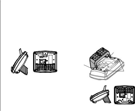
Wall mounting bracket installation (optional)
Your telephone base comes with the wall mounting/desktop bracket installed, ready for desktop use. If you prefer to mount your telephone on the wall (optional), it is designed to mount on a standard telephone wall plate. For wall mounting, follow these instructions:
•First, insert the lower portion tabs of the wall mounting/desktop bracket into the lower grooves in the telephone base, then snap the upper portion tabs of the bracket into place.
•Mount the telephone base on the wall by positioning it so the mounting studs will fit into the holes on the telephone base and wall mounting/desktop bracket. Slide the telephone base down on the mounting studs until it locks into place.
•To remove the bracket, press both upper portion tabs firmly inward and pull the bracket downward until it release from the grooves.
upper portion tab
lower portion tab
lower groove 
upper grooves
Desk/table bracket installation
To place your telephone base on a desk or table, insert the wall mounting/desktop bracket.
•Insert the lower portion tabs of the bracket into the upper grooves of the telephone base.
• Snap the upper portion tabs of the bracket into place.
•To remove the bracket, press both upper portion tabs firmly inward and pull the bracket upward until it is released from the grooves.
www.vtechphones.com

Installation
If you subscribe to DSL service
If you receive high speed internet service through your telephone line (commonly referred to as DSL) and you are experiencing interference during conversations and/or your caller ID features aren’t functioning properly, install a DSL filter to the telephone line between the telephone base and the telephone
line jack. Contact your DSL provider to obtain a DSL filter.
|
Telephone |
|
|
DSL filter (for |
|
|
|
||||
|
line cord |
|
|
DSL users) |
|
|
|
||||
|
|
|
|
|
|
|
|
|
|
|
|
|
|
|
|
|
|
|
|
|
|
|
|
|
|
|
|
|
|
|
|
|
|
|
|
 To single telephone jack (RJ11C)
Belt clip (optional)
To attach |
To remove |
|
www.vtechphones.com |
started Getting
•If the phone will not be used for a long period of time, remove the battery to prevent battery damage.
Installation
Check for dial tone
After the batteries are charged, pick up the handset and press TALK/FLASH; you should hear a dial tone. If you do not, refer to the Troubleshooting section in the back of this user’s manual.
Charge the handset battery
The battery may have enough power to allow for short calls. If the battery power is low, NEEDS RECHARGING will appear on the handset screen. For best performance charge the battery for at least 16 hours the first time.
Language
•Press PROG, then press or
or until LANGUAGE is displayed. Press SELECT.
•The current setting blinks. Press  or
or  until the screen displays the correct language (English, Espanol or Francais).
•Press SELECT to save your selection.
Set the dial mode
If you have touch tone service, the phone is ready to use as soon as the battery is charged. If you have pulse (rotary) service, you’ll need to change the dial mode.
•Press PROG.
•Press or
or until the screen displays DIAL MODE: and the current setting.
•Press SELECT. The current setting blinks.
•Press  or
or  to select TONE or PULSE.
•Press SELECT to save.
www.vtechphones.com
Installation
Set handset date and time
If you subscribe to caller ID service, the date and time will be set automatically with the first incoming call.
If you do not have caller ID service, you can set the date and time manually:
•Press PROG, then press or
or until DATE/TIME is displayed. Press SELECT.
• The month is flashing. Press |
or |
until the screen displays the correct month. Press SELECT. |
|
• The day is flashing. Press |
or |
until the screen displays the correct day. Press SELECT. |
|
• |
The hour is flashing. Press |
or |
until the screen displays the correct hour. Press SELECT. |
• |
The minute is flashing. Press |
or |
until the screen displays the correct minute. Press SELECT. |
•AM or PM is flashing. Press or
or to choose between AM or PM. Press SELECT.
Handset ringer style
You can select from four different handset ringer styles, or turn the ringer off.
1.With the handset in idle (off) mode, press PROG.
2.Press  or
or until the screen displays RINGER: and current setting.
3.Press SELECT. The current setting blinks, and you will hear a sample of the ring.
4.Press  or
or to select RINGER: 1, 2, 3, 4 or OFF. You will hear a sample of each ring tone.
5.Press SELECT to choose the displayed ringer setting.
Set ringer volume
You can select from two different handset ringer volume, or turn the ringer off.
1.Begin with the handset in idle (off) mode.
2.Press and hold  or
or  until the screen displays OFF LOW HIGH.
3.The current setting blinks, and you will hear a sample of the ring volume.
4.Press  or
or  to select ringer volume: OFF LOW HIGH. You will hear a sample of each ring tone.
5.Press SELECT to choose the displayed ringer setting.
•In the event the battery loses all of its power or is removed, the time setting will be lost.
www.vtechphones.com
started Getting
Telephone operation
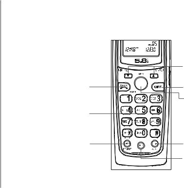
Handset layout
1.TALK
2.FLASH
3.CHAN (channel)
4.REMOVE
5.Answer a call
6. /CID VOL-
1,2
 /VOL+
/VOL+ 
7. SELECT
8. OFF 5
9. REDIAL/PAUSE
10.PROG (program)
3,4
|
6 |
SELECT |
8 |
|
|
|
7 |
|
9 |
|
10 |
10 |
www.vtechphones.com |
Telephone operation
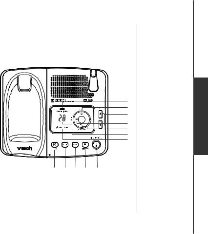
Telephone base layout
11.CHARGE/IN USE
12.Message window
13.ANS ON/OFF
14.PLAY/STOP
15.REPEAT/
16.SKIP/
17.DELETE/ X
18.VOL  /
/ 
19.CLOCK
20.SETUP
21.ANNC (announcement)
22.RECORD
23.FIND HANDSET
11
17
18

 16
16 
 15
15
14
12
13
19 20 21 22 23
www.vtechphones.com
operation Basic
11

•Whenever the phone is in use, call timer will be shown at the top right corner.
12
Telephone operation
Handset operation
Making calls
•Press TALK/FLASH, then dial the number.
—OR —
Dial the number (press  to backspace), then press TALK/FLASH.
Ending calls
• Press OFF to end your call.
— OR —
Put the handset on the telephone base or charger to end your call.
Answering Calls
• Press any key to answer a call (except OFF,  or
or  ).
).
FLASH
During a call, press TALK/FLASH to receive an incoming call, if call waiting is activated.
CHAN
Press CHAN/REMOVE to switch to a clear channel while on a call.
REMOVE
When viewing the call log, press to delete the current record displayed. While handset is in idle mode, press and hold to delete all records in the call log.
 /CID VOL- and
  /VOL+
/VOL+ 
 /CID VOL-
•While on a call, press to decrease the volume. A double beep will sound when you reach the lowest setting.
www.vtechphones.com

Telephone operation
•While phone is not in use, press to display caller ID information.
•While entering names or numbers into memory, press  then press CHAN/REMOVE to delete the last character entered.
/VOL+ 
•While on a call, press to increase the volume. A double beep will sound when you reach the highest setting.
•While phone is not in use, press to display directory entries.
•While entering names, press twice to add a space.
SELECT
Press to confirm an entry of operation, or to select highlighted item from menu.
OFF
During a call, press to hang up. While using menu, press to cancel an operation or exit the menu display.
REDIAL/PAUSE
Press to view redial number. Press it again to delete the redial number. Press to insert a dialing pause while entering a number.
PROG (program)
With the handset in idle (on-hook), press to enter programming mode.
VOL (volume)
During a call, press  or
or  to adjust the listening volume to a comfortable level.
www.vtechphones.com
operation Basic
13

•Only one handset can be on a call at a time. For example, if HS1 is on a call and HS2 presses the TALK/FLASH button, OTHER
HANDSET ON OR OUT OF RANGE will display.
.
14
Telephone operation
Telephone base operation
CHARGE/IN USE
•Flashes in unison with an incoming call’s ringing.
•Flashes slowly when the handset is in use or answering machine picks up a call or extension is off hook.
•Glows steadily when the handset is charging.
Message window
Indicate the status of answering machine. (e.g. show the number of message recorded in the mailbox.)
ANS ON/OFF
Set the answering machine to answer an incoming call.
PLAY/STOP
• Play back recorded messages in mailbox.
• Stop the playback of message.
REPEAT/
Repeat or playback the previous message during playback or as a parameters setting in the SETUP mode.
SKIP/
Skip forward a message during playback or move to the next setting in SETUP mode.
DELETE
Delete individual or all the messages.
VOL  /
/
Increase/decrease speaker volume.
CLOCK
Press to announce the current time. Press again to enter clock set mode.
SETUP
To set various answering machine features. For details, please refer to the Answering system operation section.
ANNC (announcement)
Enter announcement mode and press again to quit.
FIND HANDSET
To page handset(s).
www.vtechphones.com
Telephone operation
Temporary tone dialing
If you have pulse (rotary) dialing, you can change from pulse dialing to touch tone dialing during a call by pressing *TONE. This is useful if you need to send touch tone signals for access to telephone banking or long distance services.
1.Press *TONE when handset is off hook or on a call.
2.Dial the number.
3.After you hang up, the phone automatically returns to pulse dialing.
Call transfer
To transfer an external call from one handset (HS1) to the other handset (HS2):
For the ia5865/ia5870
1. While on a call, press selECT on HS1 to forward the call to HS2.
HS1 will show: |
HS2 will ring and show: |
CALL TRANSFERRED |
TRANSFERRED CALL |
2. Press TALK/FLASH on HS2 to answer the transferred call. HS1 will return to the idle mode.
www.vtechphones.com
•Only one handset can be on a call at a time. For example, if HS1 is on a call and HS2 presses the TALK/FLASH button, OTHER
HANDSET ON OR OUT OF RANGE will display.
•The phone will automatically return to pulse service after you hang up.
15
operation Basic
•If HS2 cannot be found, HS1 will generate an error tone and continue the call automatically. Before HS2 answers, HS1 can press
TALK/FLASH to cancel the forward function and continue the external call.
•If HS2 doesn’t respond within 30 seconds, HS1 will start ringing until
TALK/FLASH is pressed to pick up the returned call. If it is not answered within another
30 seconds, the external call will end automatically.
.
16
Telephone operation
For the ia5878/ia5884
1. While on a call, press SELECT on HS1 to forward the call to the destination handset.
HS1 will show: |
Destination handset will ring and show: |
ENTER 1-3 |
TRANSFERRED CALL |
2.Enter the destination handset number you want to transfer.
3.Press TALK/FLASH on the destination handset to answer the transferred call. HS1 will return to the idle mode.
For the ia5882/ia5890
1. While on a call, press SELECT on HS1 to forward the call to the destination handset.
HS1 will show: |
Destination handset will ring and show: |
ENTER 1-4 |
TRANSFERRED CALL |
2.Enter the destination handset number you want to transfer.
3.Press TALK/FLASH on the destination handset to answer the transferred call. HS1 will return to the idle mode.
www.vtechphones.com
 Loading...