

1. Introductions
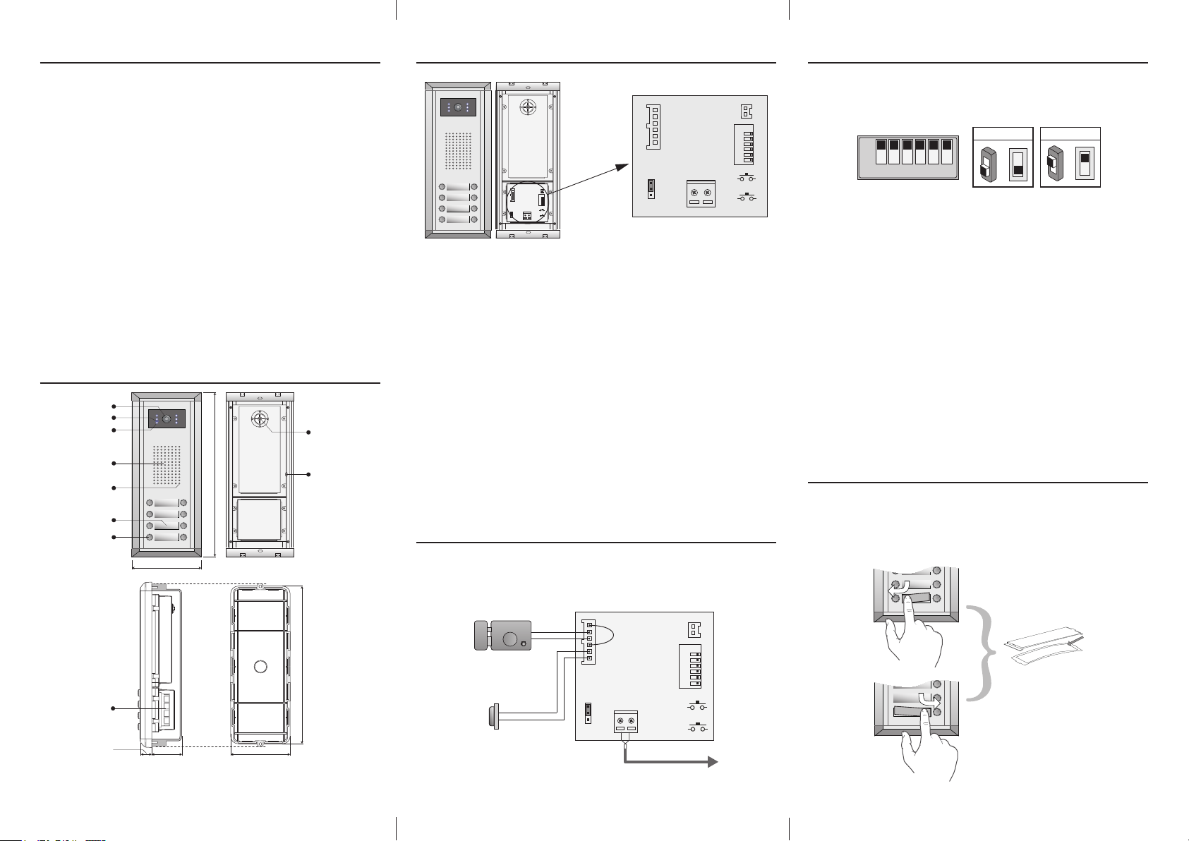
3. Terminals
5. DIP Switches settings
Door Station is a unit installed on the entrance of a building, which used to call a
user in a apartment, and control the electronic lock opening.
This is a guide for quick installation. for more detail instructions, please refer to the
DT system technical guide.
To call the user, press a button with a associated nameplate of the user; then the
user will press the Unlock button on the monitor to open the door for the visitor if
she/he is accepted.
A ID card can be use to open the door.(Only for DMR11/ID series Door Station).
For detail ID card operation, please refer to DT system technical guide.
A exit button can be connect to the Door Station directly.
The Camera angle can be adjusted to coordinate the install position of the Door
Station
2. Parts and functions
Camera Lens
CDS Sensor
Infrared LED
Speaker
Microphone
Name plate
Call button
Connection
Board
18 mm
308 mm
123 mm
45 mm 114.5 mm
Camera Angle
adjustment
Speaker Vol
adjustment
298.5 mm
+12V
LK - (GND)
CN-LK JP-LK
LK+(COM)
N.O.
EB -
EB+
DMR11
Connection Board
T/R -
+12V
T/R+
LK - (GND)
CN-LK
RS-485
LK+(COM)
ON
1 2 3 4 5 6
N.O.
EB+
EB -
SET
PA
L1
L2
1
2
PB
3
BUS
+12V:
•
12VDC power output.
LK-(GND):
•
LK+(COM):
•
NO.:
•
power ground.
electronical load activation ralay contact common.
electronical load activation ralay normally open contact(refer to DT technical
1
2
3
T/R -
T/R+
RS-485
ON
1 2 3 4 5 6
SET
L1
L2
PA
PB
BUS
guide for Lock connection detail informations).
EB+:
•
Exit button.
EB-:
•
Exit buton.
JP- LK :
•
Fo r electronic lock safety type setting(refer to Door Station Lo ck
Connections).
T/R-:
•
USB-RS485 communication terminal negative.
T/R+:
•
•
•
•
•
USB-RS485 communication terninal positive.
SET:
DIP switches for system congurations.
PA:
program button A(refer to program section).
PB:
program button B.(refer to program section).
Bus(
L1,L2): non-polarised bus line.
4. Connections
This example is one door station wiring, note that the lock used here is a 12Vdc 300mA
power-to-unlock type. (please refer to DT technical guide for Lock connection detail
informations)
Electronic Lock
-
+
Exit Button
+12V
LK - (GND)
LK+(COM)
N.O.
EB EB+
DMR11
Connection Board
JP-LK
1
L1
L2
2
3
BUS
Connect to DPS or DPS-4
T/R -
T/R+
PA
PB
ON
1 2 3 4 5 6
RS-485
SET
Total 6 bits in the DIP switches can be congured. The switches can be modied
either before or after installation, but restart the power supply is needed whenever
the switches have been modied.
1 2 3 4 5 6
ON
ON(1)
ON
=
OFF(0)
ON
=
• Bit-1 and Bit 2 is for door station ID settings, when mutil door stations are
installed in the system, these two bit must be set correctly, the first door
station set to 00, the second one set to 01, the third one set to 10, the fourth
one set to 11. If only one door station is installed, set to 00.
• Bit-3: Single line button door station or double line button door station
sel ection. If the door station is a doub le li ne button, for examlpe, the
DMR11-D8, set this bit to 0, set to 1 for single line button door stations.
• Bit-4: Button code selection; if use the default codes for each button of the
door station, set to 0, if use the programmed codes, set to 1.(the code for
each button can be program by the DT CONFIG software, see the program
section in this manual)
• Bit-5: Unlocking time quick selection, by default it is set to 0, for 1 second
unlocking time; set to 1 for 5 seconds.
• Bit-6: Debug state enter; set to activate the debug state.
6. Place Name Plate
Press down and shift right/left to open the tracsparent nameplate cover, then insert
the name paper, then put the plate cover back to the panel. Note thar double button
line panel can be opened both direction, single button line Can only be opened at
right side.
o
l
a
C
d
i
v
a
D
-1- -2- -3-
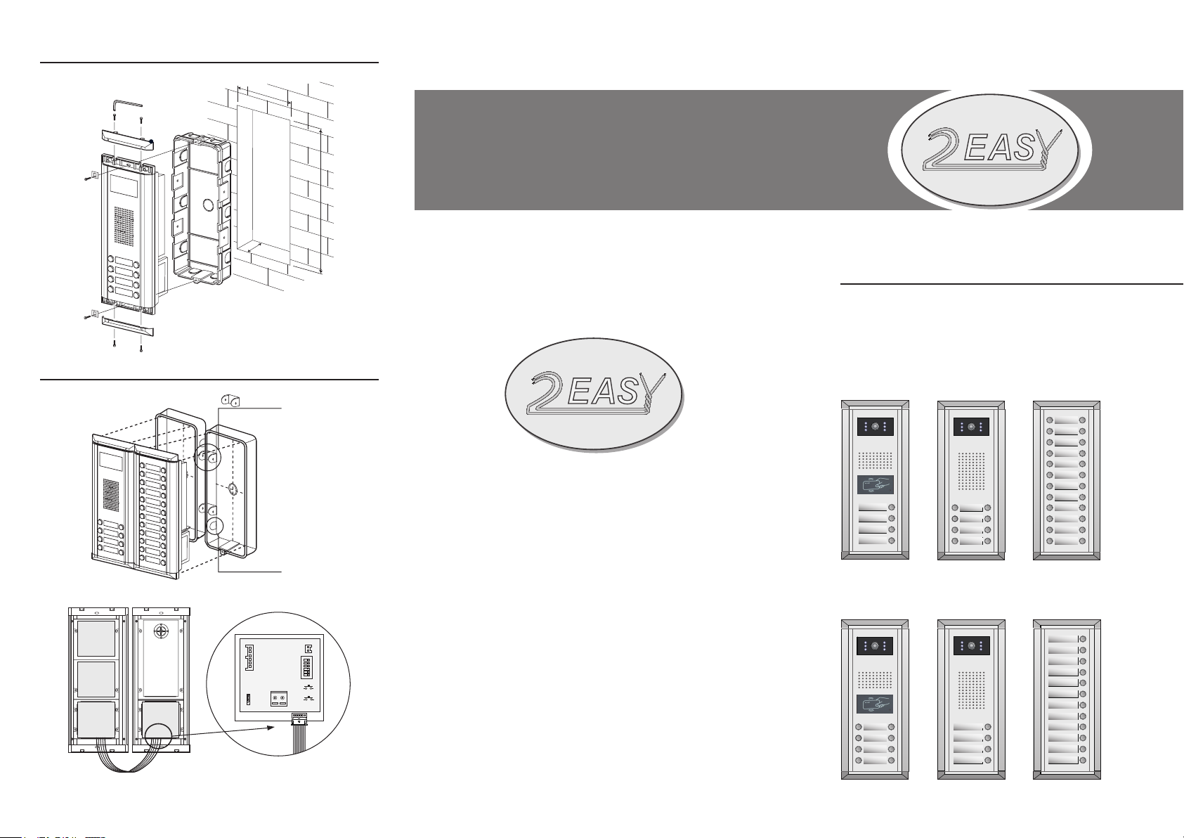
7. Standard Installation
114.5 mm
45 mm
8. Installation with expanding panel
Jointer*2
Stopper
298.5 mm
DT-ENG-DMR11-V1
DT 2-wire System
DMR11 Door Station
Quick Installation Guide
DMR11/ID/S4
DMR11/D8
EP11/D24
-4-
+12V
LK - (GND)
CN-LK JP-LK
LK+(COM)
N.O.
EB EB+
1
2
3
T/R -
T/R+
RS-485
SET
1 2 3 4 5 6
ON
PA
L1
L2
PB
BUS
DMR11/ID/D8
DMR11/S4
EP11/S12
 Loading...