


Service Manual
Trucks
Group 37
Wiring diagram
FH12, FH16 LHD
TSP23665/1
Foreword
The descriptions and service procedures contained in this manual are based on designs and methods studies carried out up to March 95.
The products are under continuous development. Vehicles and components produced after the above date may therefore have different specifications and repair methods. When this is judged to have a significant bearing on this manual, supplementary service bulletins will be issued to cover the changes.
The new edition of this manual will update the changes.
In service procedures where the title incorporates an operation number, this is a reference to V.S.T. (Volvo Standard Times).
Service procedures which do not include an operation number in the title are for general information and no reference is made to V.S.T.
The following levels of observations, cautions and warnings are used in this Service Documentation:
Note: Indicates a procedure, practice, or condition that must be followed in order to have the vehicle or component function in the manner intended.
Caution: Indicates an unsafe practice where damage to the product could occur.
Warning: Indicates an unsafe practice where personal injury or severe damage to the product could occur.
Danger: Indicates an unsafe practice where serious personal injury or death could occur.
Volvo Truck Corporation
Göteborg, Sweden
Order number: TSP23665/1
© 95 Volvo Truck Corporation, Göteborg, Sweden
All rights reserved. No part of this publication may be reproduced, stored in retrieval system, or transmitted in any forms by any means, electronic, mechanical, photocopying, recording or otherwise, without the prior written permission of Volvo Truck Corporation.
ENG01465
Contents |
|
Component wiring diagram FH12, FH16 LHD |
..................................... 2 |
Component wiring diagrams ................................................................ |
6 |
Illustrations ........................................................................................... |
48 |
Circuit board (32) electrical centre ................................................... |
114 |
Fuses on circuit board (32) electrical centre ................................... |
116 |
Relays on circuit board (32) electrical centre .................................. |
117 |
Cable harnesses ................................................................................ |
118 |
List of components ............................................................................ |
121 |
Abbreviations ..................................................................................... |
126 |
Cable colour code .............................................................................. |
127 |
Feedback |
|
1

Group 37 Wiring diagram |
Component wiring diagram FH12, FH16 LHD |
Component wiring diagram
FH12, FH16
LHD
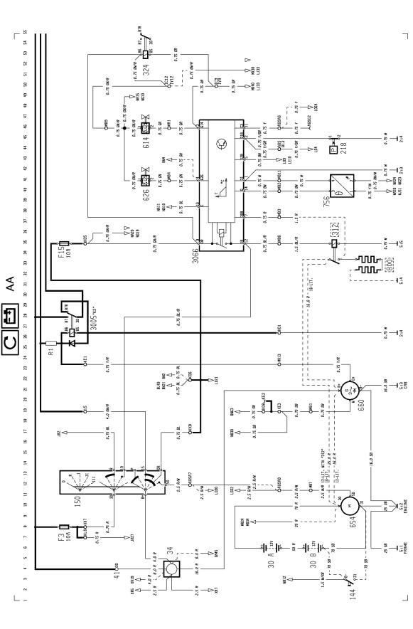
Starter system, current supply, engine preheating 24 V
FH12, Ul - unit injector, exhaust brake, exhaust pressure governor
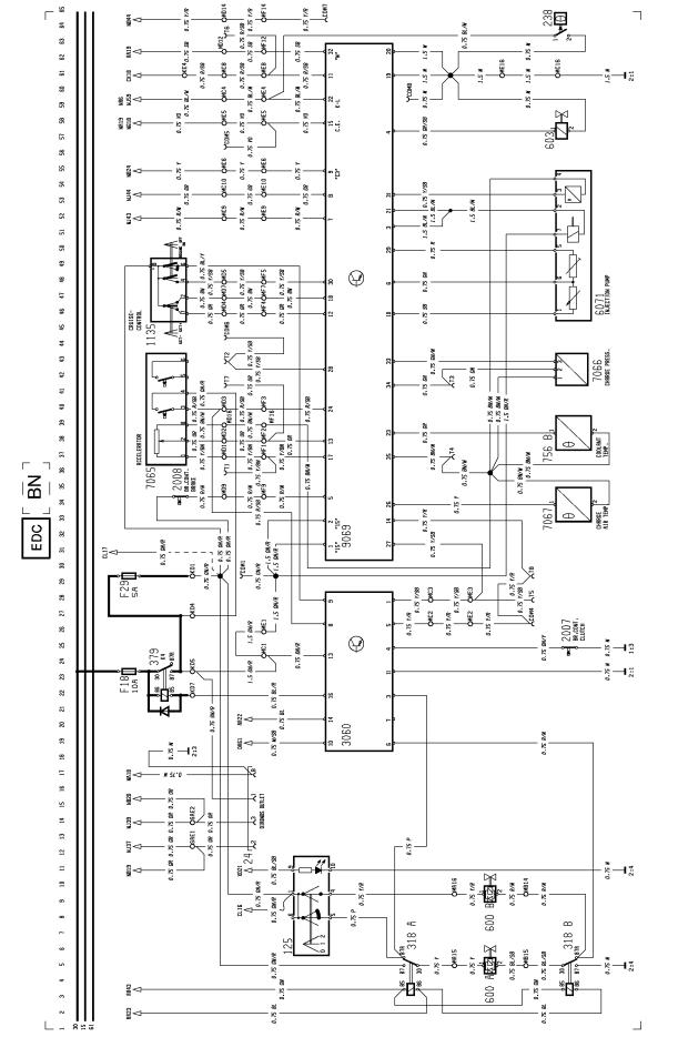
FH16, EDC - electronically controlled fuel injection, exhaust brake, exhaust pressure governor
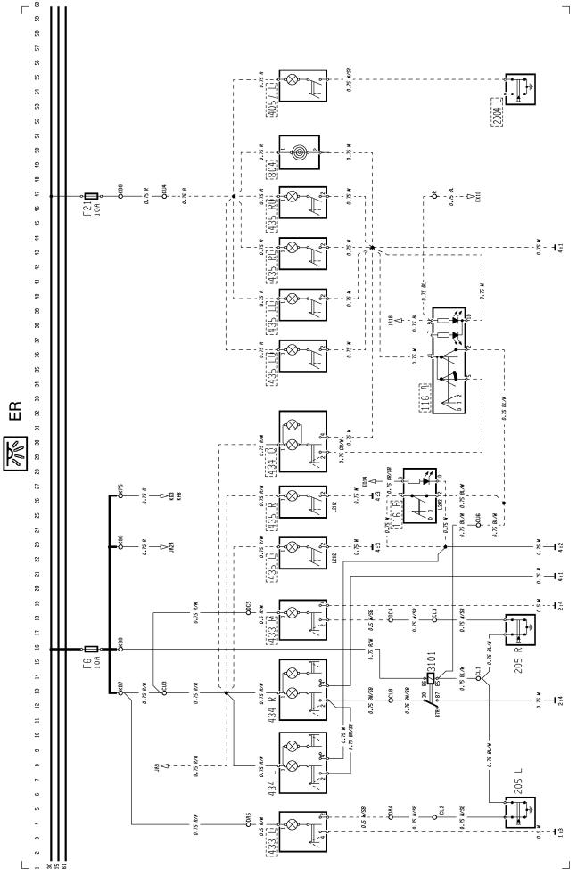
Full beams, dipped beams, parking lights, side marker lights, roof lights and tail lights
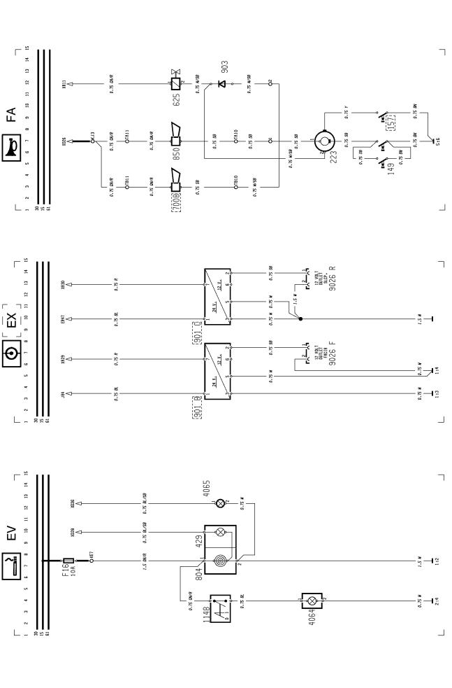
Foglights
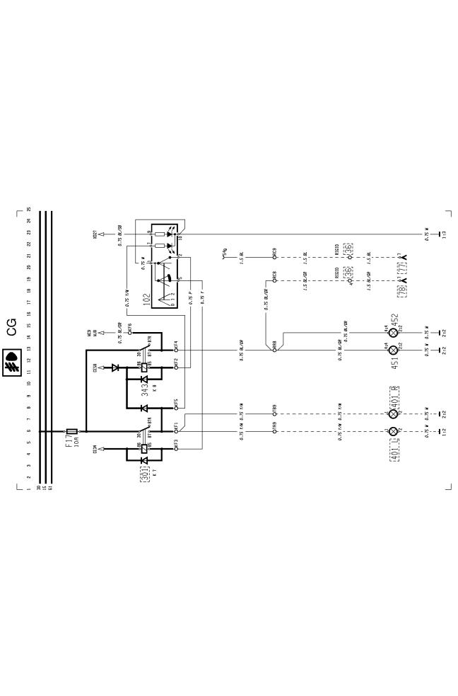
Spotlights
Brake lights
Exhaust brake and compression brake
Direction indicators, hazard warning lights
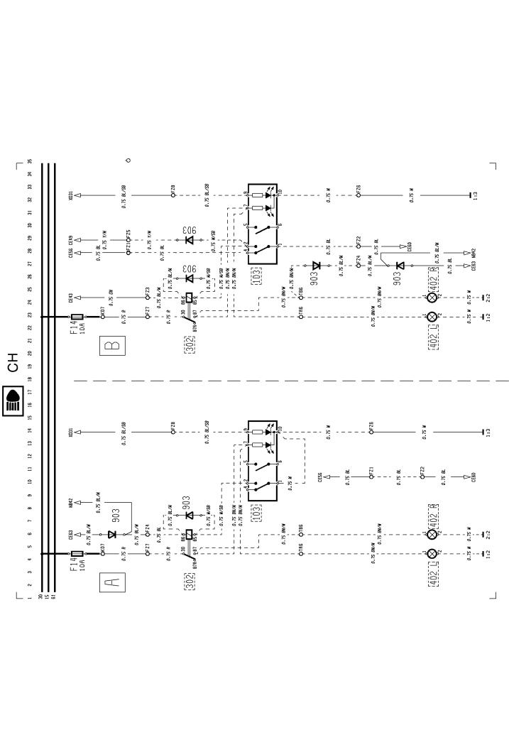
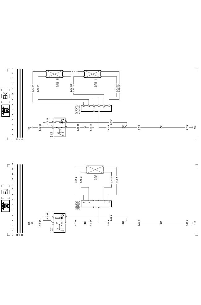
Reversing lights
Loading light, fifth wheel light
Roof sign (standard cab)
Roof sign (high cab)
Interior lights, instep lights, bunk lights and luggage compartment lights, 24 V socket
Ashtray light, cigarette lighter
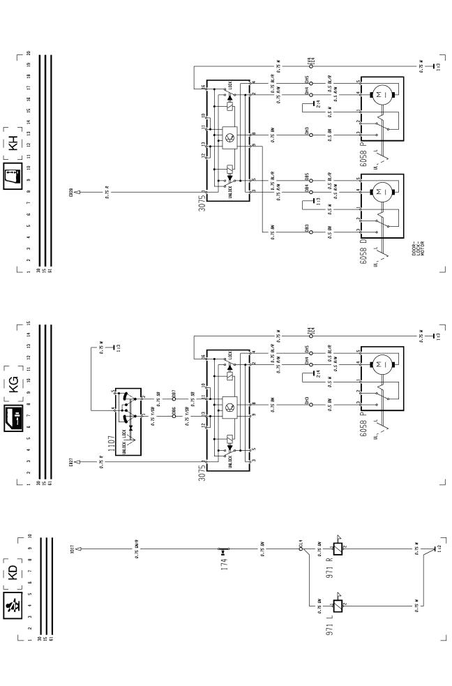
12 V socket
2

Group 37 Wiring diagram |
Component wiring diagram FH12, FH16 LHD |
Horn
Reverse warner
Windscreen wipers and washers, headlamp wipers and washers
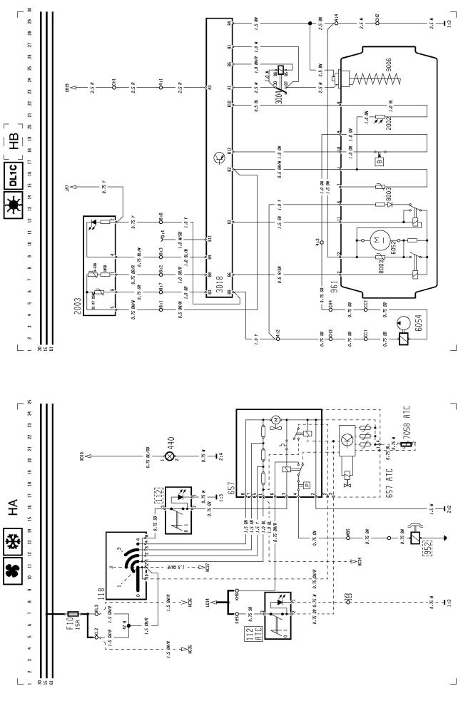
Air conditioning
Cab heater (DL1C)
Engine/cab heater (DW80)
Heated seat
Electrically adjustable seat
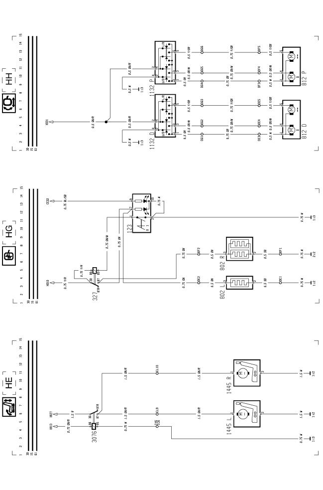
Electrically heated rearview mirror
Electrically operated rearview mirror
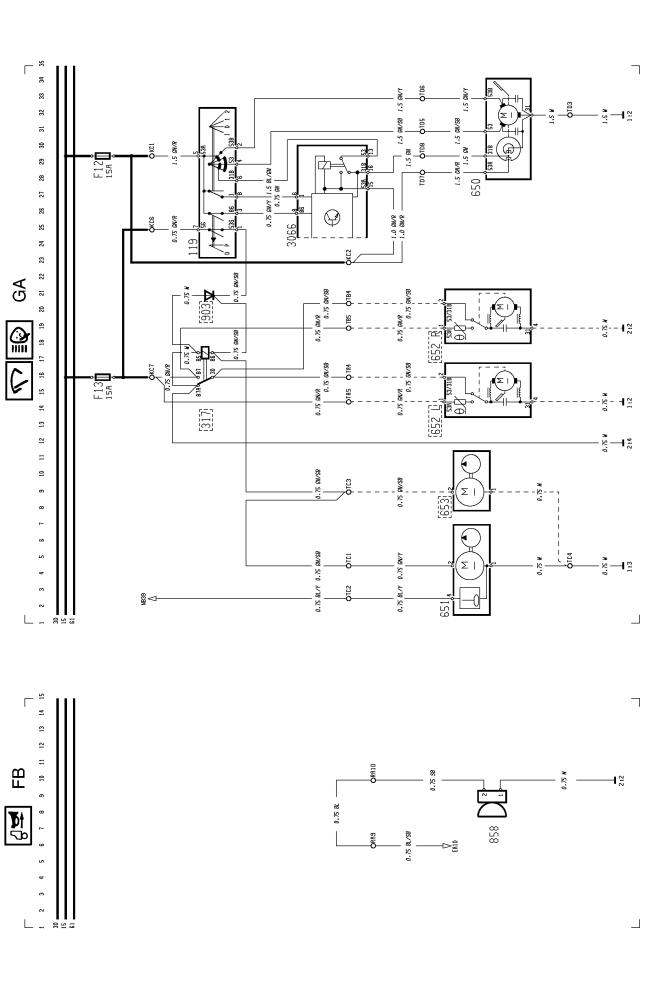
Air dryer
Fuel filter heater
Cab tilt unit
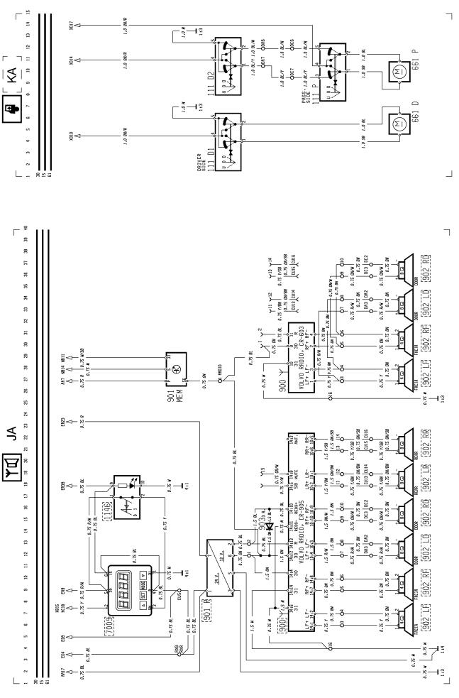
Radio, voltage converter, loudspeaker, alarm clock/timer
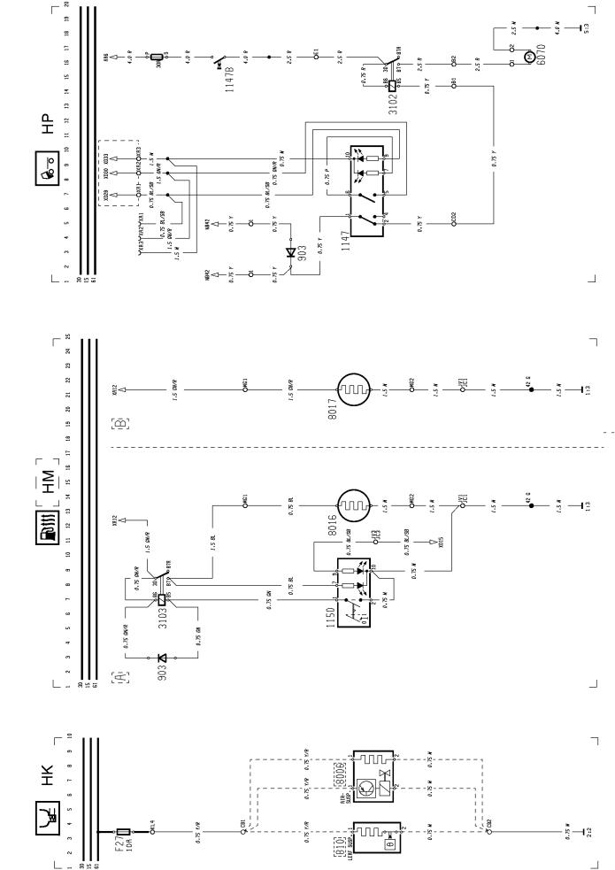
Electrically operated window winder
Seat belt
Electrically operated door lock
3

Group 37 Wiring diagram |
Component wiring diagram FH12, FH16 LHD |
Central lock
Power take-off
Double power take-off
Diff. lock
Lock, 3rd axle, bogie lift
Lock, 3rd axle
Geartronic
Bogie lift (hydraulic)
Bogie lift (hydraulic), with axle load limiter
Air suspension 4x2
Bogie lift, air suspension < 15 tonnes
Air suspension 6x2 < 15 tonnes with time limitation
Bogie lift, pusher
Bogie lift, air suspension <15 tonnes
4

Group 37 Wiring diagram |
Component wiring diagram FH12, FH16 LHD |
Drive axle load increase
Drive axle load increase with time limitation
Bogie press, 6x2 air suspension
Bogie load, 6x4 air suspension with time limitation
Left-hand unit in instrument panel (standard design)
Central unit in instrument panel
Right-hand unit in instrument panel (standard design)
Left-hand unit in instrument panel (Driver Information System — DIS)
Combination instrument (Driver Information System — DIS)
Anti-lock brakes (ABS), 4-channel
Level control, headlights
Extra fuses
Connection of extra switch, rheostat
Earth connections
ADR (battery master switch, current limiter, emergency stop)
ADR cab heater (DL1C)
5
Group 37 Wiring diagram |
Component wiring diagrams |
Component wiring diagrams
6

Group 37 Wiring diagram |
Component wiring diagrams |
7
Group 37 Wiring diagram |
Component wiring diagrams |
8
Group 37 Wiring diagram |
Component wiring diagrams |
9
Group 37 Wiring diagram |
Component wiring diagrams |
10
Group 37 Wiring diagram |
Component wiring diagrams |
11

Group 37 Wiring diagram |
Component wiring diagrams |
12

Group 37 Wiring diagram |
Component wiring diagrams |
13
Group 37 Wiring diagram |
Component wiring diagrams |
14
Group 37 Wiring diagram |
Component wiring diagrams |
15
Group 37 Wiring diagram |
Component wiring diagrams |
16
Group 37 Wiring diagram |
Component wiring diagrams |
17
Group 37 Wiring diagram |
Component wiring diagrams |
18
Group 37 Wiring diagram |
Component wiring diagrams |
19
Group 37 Wiring diagram |
Component wiring diagrams |
20
Group 37 Wiring diagram |
Component wiring diagrams |
21
Group 37 Wiring diagram |
Component wiring diagrams |
22
Group 37 Wiring diagram |
Component wiring diagrams |
23

Group 37 Wiring diagram |
Component wiring diagrams |
24
Group 37 Wiring diagram |
Component wiring diagrams |
25

Group 37 Wiring diagram |
Component wiring diagrams |
26

Group 37 Wiring diagram |
Component wiring diagrams |
27
Group 37 Wiring diagram |
Component wiring diagrams |
28
 Loading...