


Trucks
Group 37
Release 02
Wiring diagram
FM9, FM12, FH12 VERSION2
TSP175664

Foreword
The descriptions and service procedures contained in this manual are based on designs and methods studies carried out up to August 02.
The products are under continuous development. Vehicles and components produced after the above date may therefore have different specifications and repair methods. When this is judged to have a significant bearing on this manual, supplementary service bulletins will be issued to cover the changes.
The new edition of this manual will update the changes.
In service procedures where the title incorporates an operation number, this is a reference to V.S.T. (Volvo Standard Times).
Service procedures which do not include an operation number in the title are for general information and no reference is made to V.S.T.
The following levels of observations, cautions and warnings are used in this Service Documentation:
Note: Indicates a procedure, practice, or condition that must be followed in order to have the vehicle or component function in the manner intended.
Caution: Indicates an unsafe practice where damage to the product could occur.
Warning: Indicates an unsafe practice where personal injury or severe damage to the product could occur.
Danger: Indicates an unsafe practice where serious personal injury or death could occur.
Volvo Truck Corporation
Göteborg, Sweden
The following information will be superseded by this manual:
SM Group 37 |
TSP 169444 |
Order number: TSP175664
© 02 Volvo Truck Corporation, Göteborg, Sweden
All rights reserved. No part of this publication may be reproduced, stored in retrieval system, or transmitted in any forms by any means, electronic, mechanical, photocopying, recording or otherwise, without the prior written permission of Volvo Truck Corporation.
ENG11869
Contents |
|
Example of wiring diagram ................................................................... |
2 |
Component wiring diagram index ....................................................... |
5 |
Component wiring diagrams ................................................................ |
8 |
Illustrations index ................................................................................ |
76 |
Illustrations ........................................................................................... |
77 |
Fuses ................................................................................................... |
137 |
Relays ................................................................................................. |
139 |
Wiring harness illustration index ..................................................... |
141 |
Earth connections ............................................................................. |
144 |
List of earth connections ................................................................... |
146 |
List of connectors ............................................................................. |
147 |
List of components ........................................................................... |
154 |
Abbreviations ..................................................................................... |
160 |
Cable colour code ............................................................................. |
161 |
Feedback |
|
1
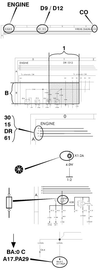
Example of wiring diagram
Component wiring diagram title, variant/subtitle and symbol.
Coordinates (B 1).
30 Voltage battery, kl.30.
15 Voltage with starter key in drive position, kl.15.
DR Voltage with starter key in drive position, preheat position and start position, kl.DR.
61 Voltage when alternator charges, kl.61.
Splice.
Fuse.
Reference arrow, for diagram BA, coordinates 0 C, component A17, connector PA pin 29.
2
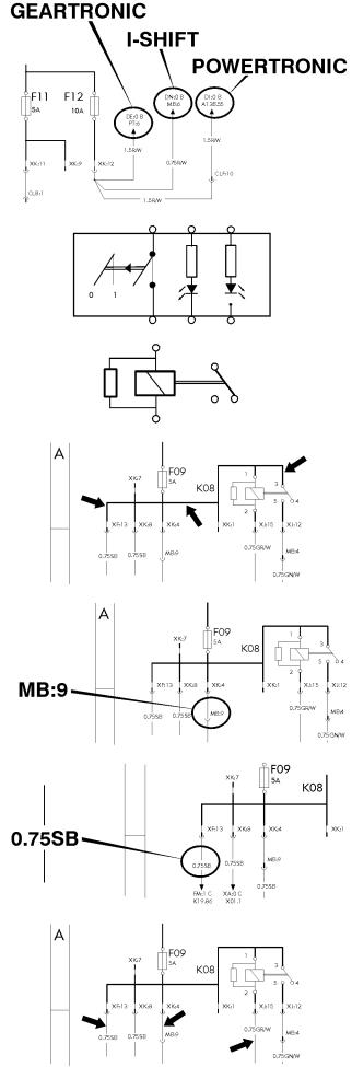
The maximum of variants are drawn, think about that all wires and components are not standard for all markets or vehicle models.
Switch.
Relay.
Conductor on circuit card.
Connector MB terminal 9.
Wire area and colour.
Thin lines, wires.
3
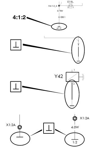
Earth connection point 4, earth connection 1 and wire 2.
Earth connection to circuit card.
Earth connection without wire.
Same splice can be drawn on several diagrams. The wire from the splice to the earth connection point will only be drawn and coded on one diagram. On the other diagrams will only the earth connection point be written besides the splice.
4
AA AE BA BI BM BN BU CM CO CP CS CU DB DE DI DM DN DQ DU EC EE EI EM EN EQ FA FG FK FM FP FQ FU GA
Component wiring diagram index
Power supply, starting system .........................................................................................
ADR, main switch ............................................................................................................
Vehicle ECU ....................................................................................................................
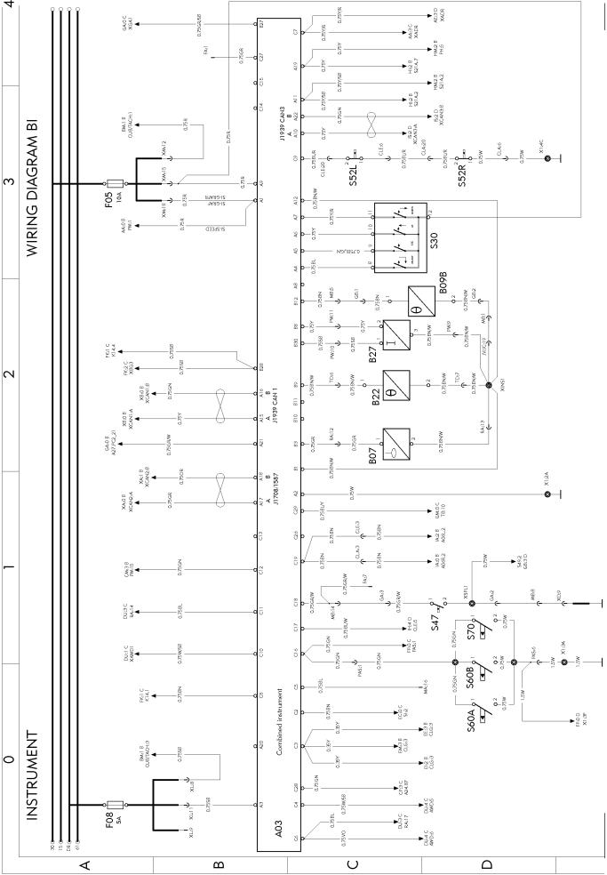
Instrument cluster ............................................................................................................
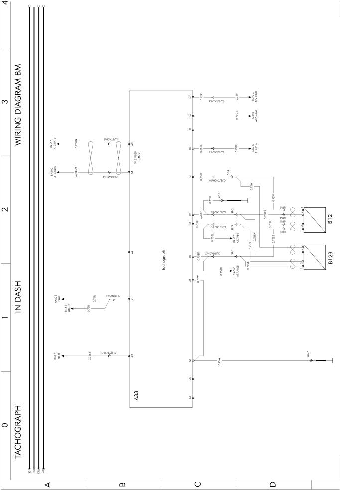
Tachograph in dash .........................................................................................................
Tachograph in shelf .........................................................................................................
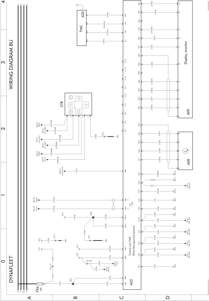
Dynafleet .........................................................................................................................
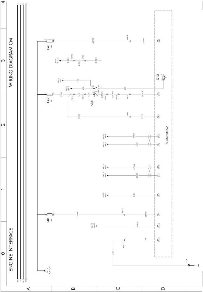
Engine interface ...............................................................................................................
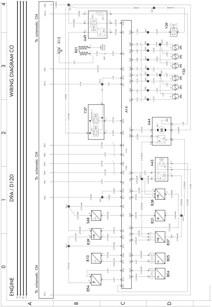
Engine (D9/D12) ..............................................................................................................
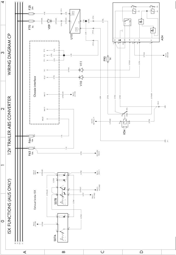
ISX functions, 12V trailer ABS converter (AUS only) .....................................................
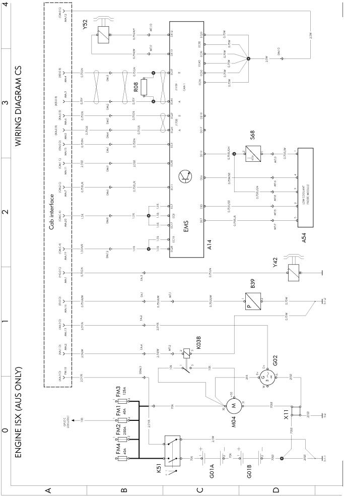
Engine ISX (AUS only) ....................................................................................................
Fuel filter water drain .......................................................................................................
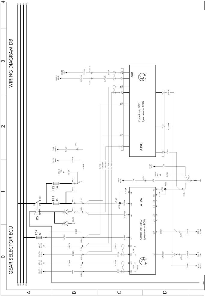
Gear selector ECU ..........................................................................................................
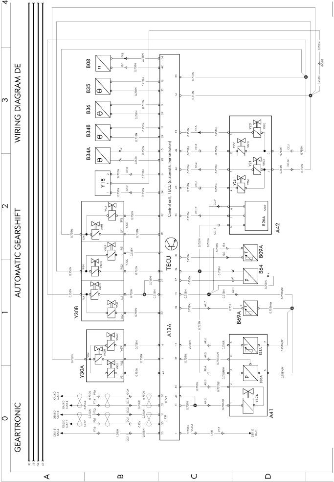
Geartronic automatic gearshift ........................................................................................
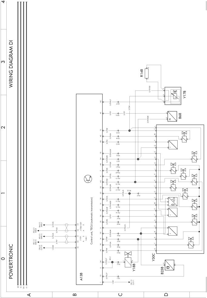
Powertronic ......................................................................................................................
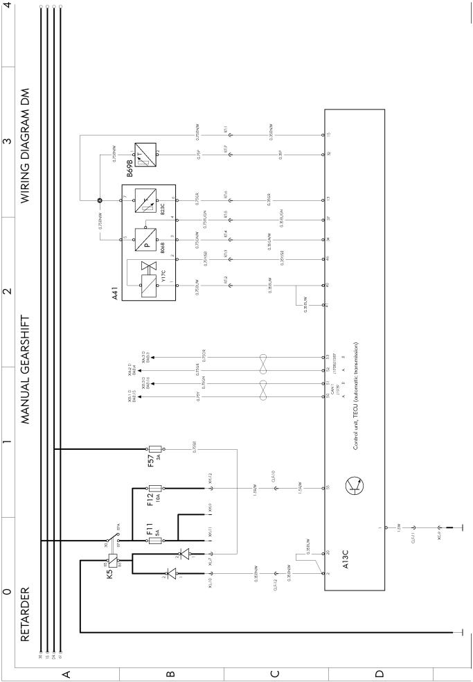
Retarder manual gearshift ...............................................................................................
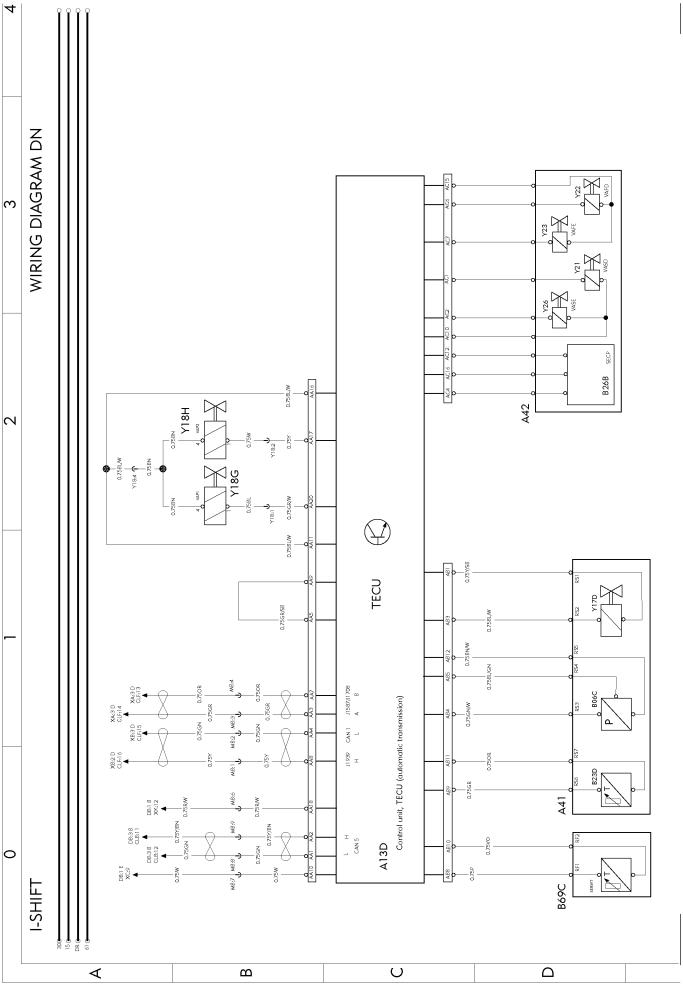
I-shift ................................................................................................................................
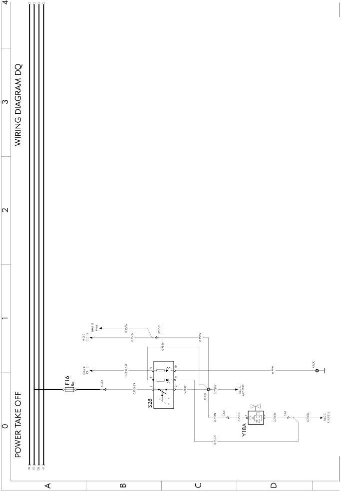
Power take off ..................................................................................................................
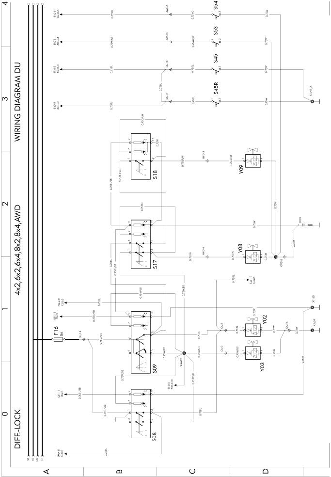
Diff-lock ............................................................................................................................
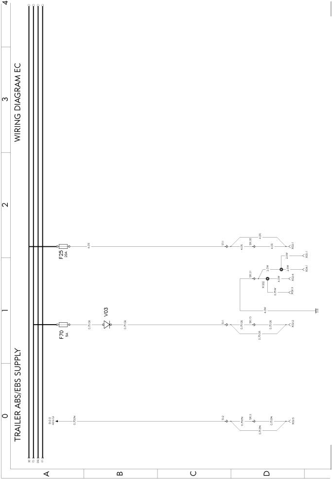
Trailer ABS/EBS supply ...................................................................................................
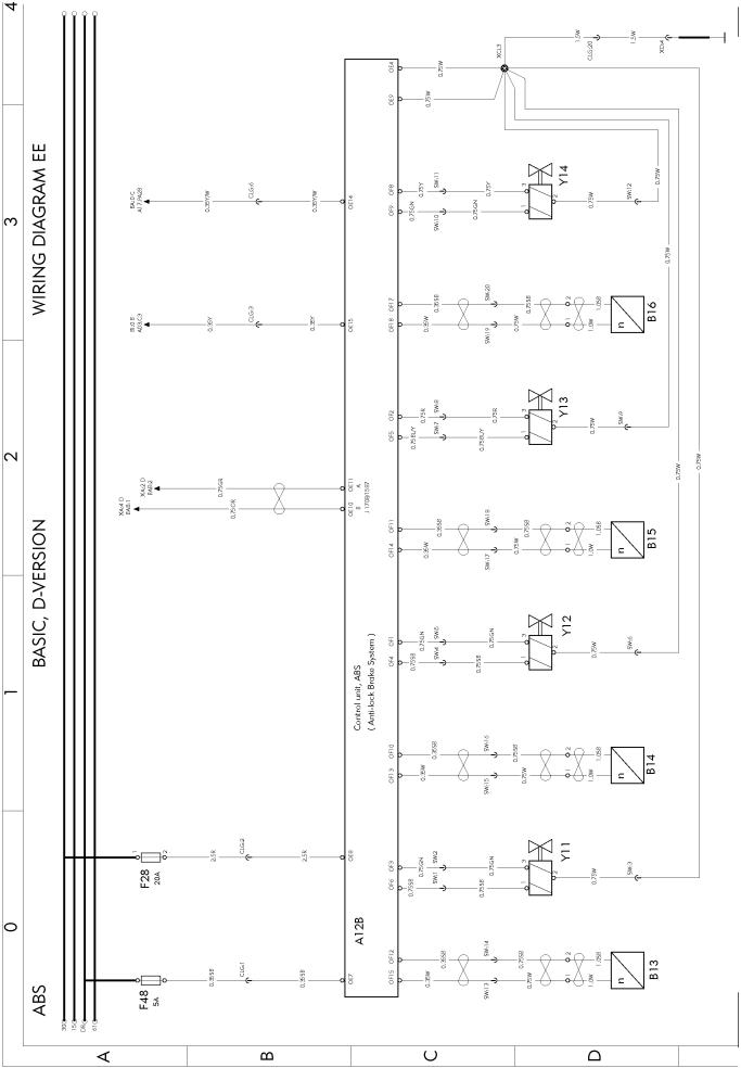
ABS basic, D-version ......................................................................................................
ABS/ASR D-version .........................................................................................................
EBS ECU .........................................................................................................................
EBS modulators ..............................................................................................................
ESP .................................................................................................................................
Air-suspension ................................................................................................................
Load indikator ..................................................................................................................
Bogie lift A-ride ................................................................................................................
Axle lock, self steered axle .............................................................................................
Hydraulic steered axle .....................................................................................................
Air dryer ...........................................................................................................................
Central lubrication system ...............................................................................................
LCM head lights ..............................................................................................................
page 8 page 9 page 10 page 11 page 12 page 13 page 14
page 15
page 16
page 17
page 18
page 19
page 20
page 21
page 22
page 23
page 24
page 25
page 26
page 27
page 28
page 29
page 30
page 31
page 32
page 33
page 34
page 35
page 36
page 37
page 38
page 39
page 40
5
GB GC GK GM GQ GU HG HI HM HP HY IA IE IF IH IM IQ IR IS IU IX IZ KA KE KI KM ME NA NC NI NK NR NU XA XB
LCM trailer, HL-HID .........................................................................................................
LCM rear lights ................................................................................................................
Trailer connections (AUS only) ........................................................................................
Wiper, washer ..................................................................................................................
Horn .................................................................................................................................
Headlights adjust .............................................................................................................
Climate unit, CU,-BAS,-MCC,-ECC .................................................................................
Air heater .........................................................................................................................
Water heater ....................................................................................................................
Short stop cabheater .......................................................................................................
Climat unit, CU,-HEAT,-ACMAN,-ACAUT. .......................................................................
El. heated/adj. seat .........................................................................................................
El. heat/adj. mirrors, El. window winders ........................................................................
Foldable mirror bracket ....................................................................................................
Interior light ......................................................................................................................
Central locking, immobiliser ............................................................................................
El. sunroof, cig. lighter, refrigerator .................................................................................
12V power supply ............................................................................................................
SWM, SRS. Air-bag .........................................................................................................
Radio ...............................................................................................................................
Intergrated telephone ......................................................................................................
Backup camera ................................................................................................................
Cab tilt .............................................................................................................................
Load light, 5:th wheel lamp .............................................................................................
Light sign .........................................................................................................................
Beacon warning light .......................................................................................................
Extra fuse block, key switch relay ...................................................................................
Body builder (BB), auxsw-6 and swapbody ....................................................................
Body builder (BB), ELCE-CK, BBM, PTO2 .....................................................................
Extra spotlamps front/roof, max 4x70W ..........................................................................
Burglar alarm ...................................................................................................................
Body builder (BB), tipper tractor ”HYDRKIT” ..................................................................
Body builder (BB), DUAL-SPEED ...................................................................................
Bus J1708/J1587 .............................................................................................................
Bus J1939 .......................................................................................................................
page 41
page 42
page 43
page 44
page 45
page 46
page 47
page 48
page 49
page 50
page 51
page 52
page 53
page 54
page 55
page 56
page 57
page 58
page 59
page 60
page 61
page 62
page 63
page 64 page 65 page 66 page 67
page 68
page 69
page 70
page 71
page 72
page 73
page 74
page 75
6
Component wiring diagrams
7
T3016280
8
T3016252
9

T3016253
10
T3016254
11
T3016255
12

T3016256
13
T3016257
14
T3016258
15
T3016259
16
T3016260
17
T3016261
18
T3016262
19
T3016263
20
T3016264
21
T3016265
22
T3016266
23
T3016267
24
T3016268
25
T3016269
26
T3016270
27
T3016271
28
 Loading...