


Volvo Trucks North America
Greensboro, NC USA
Service Bulletin
Trucks
This Service Bulletin replaces Service Bulletin, |
Date |
Group |
No. |
Release Page |
|
4.2010 |
431 |
03 |
1(38) |
||
431–03 “I-Shift Transmission, Design and |
|||||
|
Function” dated 1.2008.
Design and Function
I-Shift Transmission
Transmission, Design and Function
T4021207
The I-Shift transmission is a technologically advanced automated mechanical transmission, designed specifically to work in conjunction with Volvo’s new family of heavy-duty diesel engines. In order to work as a total package, the I-Shift is programmed with each engines’ efficiency map and is offered with different software options to fulfill each operators needs.
• “Transmission, Mechanical”, page 2
PV776-88949834 |
USA39152 |
Volvo Trucks North America |
Date |
Group |
No. |
Release |
Page |
Service Bulletin |
4.2010 |
431 |
03 |
|
2(38) |
Transmission, Mechanical
General
All variants of the Volvo I-Shift have 12 forward speeds and up to 4 reverse speeds depending on programming. It is a single countershaft transmission built up with a splitter section, a main section with three forward and one reverse gear, and a range gear section. It is an automated mechanical transmission and uses synchronizers in its splitter and range gears but not in the main section. The main section utilizes a countershaft brake to mesh gears and equalize shaft speeds as needed. A single disc automated clutch system is utilized in place of a torque converter. The I-Shift is a "two pedal" transmission and does not require a clutch pedal.
The I-Shift uses compressed air and electrical solenoids to perform shift functions, clutch control and countershaft
brake functions. All of these functions are timed and controlled by the transmission control module (TCM). A dedicated air tank is needed on the vehicle to supply air for these components. The air is plumbed to the transmission via a supply line and is distributed to the other components internally. The air control solenoids are housed in the transmission control housing and in the clutch control valve assembly.
All Volvo Truck models will be available with this transmission including the VT, VN Series & VHD vocational trucks. Multiple I-Shift models will be offered to support the power ranges of the engines as well as offering different gear arrangements.
|
AT2512C |
ATO2512C |
AT2812C |
ATO3112C |
Operation |
Two Pedal |
Two Pedal |
Two Pedal |
Two Pedal |
|
|
|
|
|
Forward Speeds |
12 |
12 |
12 |
12 |
Engines Available |
D11/D13 |
D11/D13 |
D16 |
D16 |
|
|
|
|
|
Overall Ratio |
14.94:1 |
15.04:1 |
14.94:1 |
15.04:1 |
Top Ratio |
Direct 1.00:1 |
Overdrive 0.78:1 |
Direct 1.00:1 |
Overdrive 0.78:1 |
|
|
|
|
|
Weight lbs (kg) |
597 (275) |
597 (275) |
610 (281) |
610 (281) |
|
AT2612D |
ATO2612D |
ATO3112D |
|
|
|
|
Operation |
Two Pedal |
Two Pedal |
Two Pedal |
|
|
|
|
Forward Speeds |
12 |
12 |
12 |
|
|
|
|
Engines Available |
D11/D13 |
D11/D13 |
D16 |
|
|
|
|
Overall Ratio |
14.94:1 |
15.04:1 |
15.04:1 |
|
|
|
|
Top Ratio |
Direct 1.00:1 |
Overdrive 0.78:1 |
Overdrive 0.78:1 |
|
|
|
|
Weight lbs (kg) |
614 (279) |
614 (279) |
627 (285) |
|
|
|
|
Volvo Trucks North America |
Date |
Group |
No. |
Release |
Page |
Service Bulletin |
4.2010 |
431 |
03 |
|
3(38) |
Transmission Identification
Each transmission has two identification tags. One is found |
back of the range housing. The transmission version can |
||
onthetopoftheclutchhousingandtheotherisfoundonthe |
be readily identified by the following nomenclature table. |
||
|
|
|
|
Make |
Volvo |
|
|
|
|
||
Type |
AT2512C, ATO2512C, AT2612D, ATO2612D, AT2812C, ATO3112C, and ATO3112D |
||
|
|
|
|
Transmission |
|
|
|
Nomenclature |
A — Automatic |
|
|
|
T — Transmission |
|
|
|
O — Overdrive |
|
|
|
25 |
— Torque Capacity 2500 Nm (1850 ft-lb) |
|
|
26 |
— Torque Capacity 2600 Nm (1900 ft-lb) |
|
|
28 |
— Torque Capacity 2800 Nm (2050 ft-lb) |
|
|
31 |
— Torque Capacity 3100 Nm (2300 ft-lb) |
|
|
12 |
— Number of forward gears |
|
|
C or D — Design Level |
|
|
|
|
|
|
Gear Ratio
Gear ratios for AT2512C, AT2612D, AT2812C, ATO2512C, ATO2612D, ATO3112C, and ATO3112D are as shown in the table:
|
12 geared AT2512C, AT2612D, |
12 geared ATO2512C, ATO2612D, |
Gear selection |
AT2812C |
ATO3112C, ATO3112D |
1st |
14.94:1 |
11.73:1 |
2nd |
11.73:1 |
9.21:1 |
3rd |
9.04:1 |
7.09:1 |
4th |
7.09:1 |
5.57:1 |
5th |
5.54:1 |
4.35:1 |
6th |
4.35:1 |
3.41:1 |
7th |
3.44:1 |
2.70:1 |
8th |
2.70:1 |
2.12:1 |
9th |
2.08:1 |
1.63:1 |
10th |
1.63:1 |
1.28:1 |
11th |
1.27:1 |
1.00:1 |
12th |
1.00:1 |
0.78:1 |
Reverse gear R1 |
17.48:1 |
13.73:1 |
Reverse gear R2 |
13.73:1 |
10.78:1 |
Reverse gear R3 |
4.02:1 |
3.16:1 |
Reverse gear R4 |
3.16:1 |
2.48:1 |
|
|
|
Volvo Trucks North America |
Date |
Group |
No. |
Release |
Page |
Service Bulletin |
4.2010 |
431 |
03 |
|
4(38) |
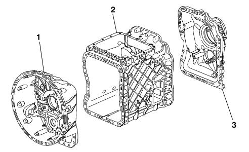
Transmission Construction
The transmission has three main parts: a clutch housing, main housing and range housing. The clutch housing (1) also forms the front wall of the transmission housing. The main housing (2) contains the main, counter and reverse
shafts along with the selector assembly which is integrated into the transmission control housing. The range housing
(3) contains the range planetary gear assembly and output shaft.
W4002905
1Clutch housing
2Main housing
3Range housing
Volvo Trucks North America |
Date |
Group |
No. |
Release |
Page |
Service Bulletin |
4.2010 |
431 |
03 |
|
5(38) |
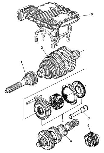
The main internal parts in the transmission are the input shaft (1), main shaft (2), range gear with selector unit (3), countershaft (4), oil pump with reverse shaft (5), control housing with selector unit (6) and if equipped, a power takeoff (PTO) drive shaft (7).
The trailing wheel for the reverse gear, the main gears and the range sections sun gear are located on the main shaft. The range section also incorporates planetary gears that are integrated with the output shaft. The countershaft has fixed gears.
T4021728
1Input shaft
2Main shaft
3Range gear with selector unit
4Countershaft
5Oil pump with reverse shaft
6Control housing with selector unit
7Drive shaft for PTO
Volvo Trucks North America |
Date |
Group |
No. |
Release |
Page |
Service Bulletin |
4.2010 |
431 |
03 |
|
6(38) |
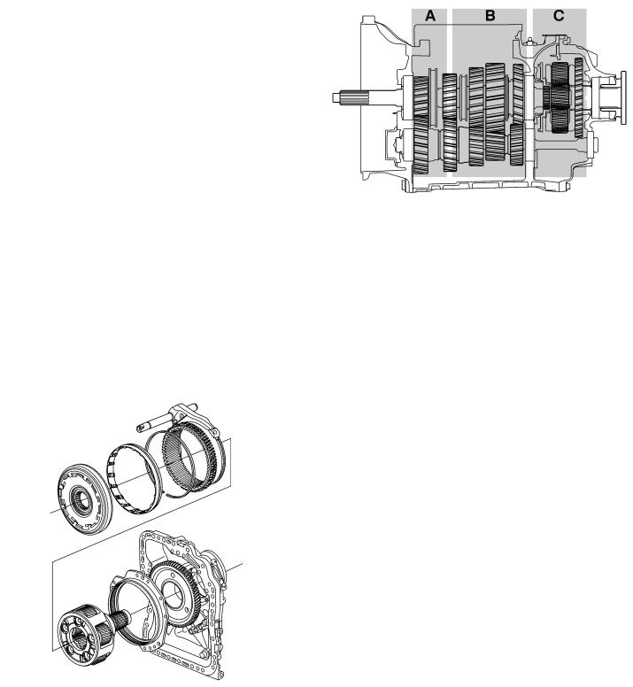
Synchronization
•The split gear (A) is synchronized.
•The main transmission housing gears (B) are non—synchronized, but instead utilize a countershaft brake to equalize shaft speeds and mesh the gears. For more information see, page 11.
•The range gear (C) is synchronized.
T4021404
Range Gear
The range gears synchronization lies outside the ring gear, reducing the unit’s length. The large synchronization area results in short selection time; the wide planetary gears offer strength and the helical gears result in a quiet planetary gear operation.
W4002906
Range gear assembly with selector unit
Volvo Trucks North America |
Date |
Group |
No. |
Release |
Page |
Service Bulletin |
4.2010 |
431 |
03 |
|
7(38) |
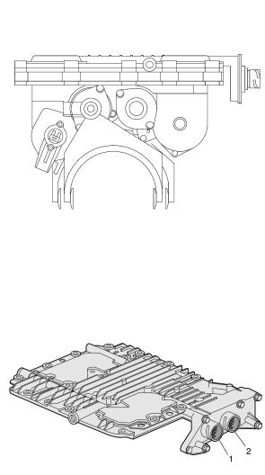
Control Housing Assembly
The control housing assembly contains the transmission control module (TCM), shift solenoids, countershaft brake solenoid, gear position sensors, oil temperature sensor, shaft speed sensors, the shift forks and their shift cylinders. When a gear is selected using the gear selector, these components work in conjunction with the engine control module (ECM) to reduce the engine torque to a suitable level, before the control housing shifts the transmission to neutral and then to the selected gear. The solenoids are used to control pressurized air to cylinders, that perform the action of changing the gears. The control housing also contains and controls the countershaft brake solenoid. This solenoid controls air pressure to the brake assembly which aids in synchronizing the shaft speeds to mesh the main gears. After the transmission has been put into neutral, the ECM begins to adjust engine speed (RPM) to accommodate the selected gear after the shift takes place.
The control housing cover has two electrical sockets and also contains the TCM.
1 Vehicle communication
2 Clutch cylinder
W4002915
W4002936
Volvo Trucks North America |
Date |
Group |
No. |
Release |
Page |
Service Bulletin |
4.2010 |
431 |
03 |
|
8(38) |
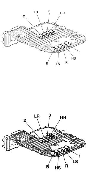
The control housing cover contains nine solenoid valves that control the path of pressurized air:
2.Solenoid valve 2nd gear
LR. Solenoid valve, low range
3.Solenoid valve 3rd gear
HR. Solenoid valve, high range
B.Solenoid valve, brake
LS. Solenoid valve, low split
R.Solenoid valve, reverse
HS. Solenoid valve, high split
1.Solenoid valve 1st gear
2.Solenoid valve 2nd gear
LR. Solenoid valve, low range
3.Solenoid valve 3rd gear
HR. Solenoid valve, high range
B.Solenoid valve, brake
HS. Solenoid valve, high split
R.Solenoid valve, reverse
LS. Solenoid valve, low split
1.Solenoid valve 1st gear
W4002918
Overdrive Transmissions
T4018189
Direct Drive Tranmission
Volvo Trucks North America |
Date |
Group |
No. |
Release |
Page |
Service Bulletin |
4.2010 |
431 |
03 |
|
9(38) |
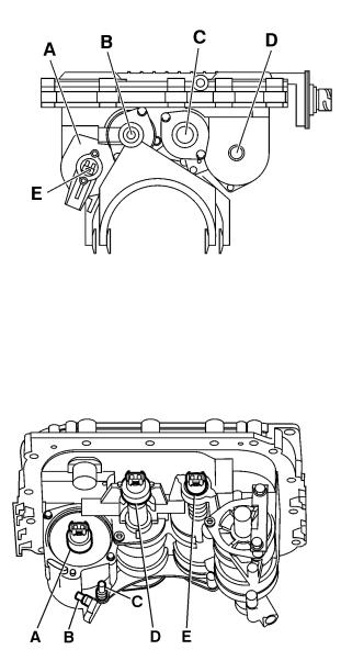
The following shows the locations of the four parallel cylinders and one of the cylinder position sensors.
A.Split cylinder
B.1/R cylinder
C.2/3 cylinder
D.Range cylinder
E.Split cylinder position sensor
T4018494
The following shows the locations of the other three cylinder position sensors and the speed sensors.
A.Range cylinder position sensor
B.Countershaft speed sensor
C.Main shaft speed sensor
D.2nd/3rd gear cylinder position sensor
E.1st/reverse cylinder position sensor
T4018201
Volvo Trucks North America |
Date |
Group |
No. |
Release |
Page |
Service Bulletin |
4.2010 |
431 |
03 |
|
10(38) |
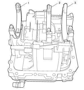
The following shows the locations of the other three shift forks.
1.1st-Reverse gear shift fork
2.2nd-3rd gear shift fork
3.Splitter gear shift fork
W4002920
Volvo Trucks North America |
Date |
Group |
No. |
Release |
Page |
Service Bulletin |
4.2010 |
431 |
03 |
|
11(38) |
Countershaft Brake
The countershaft brake is located at the front of the countershaft within the clutch housing. It is used to stop the rotating parts in the transmission when a starting gear is selected, which eliminates transmission wear and noise. The brake is also used when changing gears, to aid in synchronizing the shaft speeds for quicker gear changes. It is activated by a solenoid contained in the control housing. The solenoid controls pressurized air flow to the brakes integrated pneumatic cylinder which applies pressure to friction and steel disc plates.
T4021408
Countershaft brake location
T4022010
Countershaft brake discs
Volvo Trucks North America |
Date |
Group |
No. |
Release |
Page |
Service Bulletin |
4.2010 |
431 |
03 |
|
12(38) |
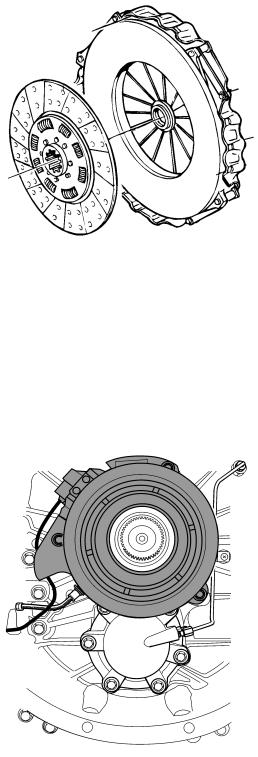
Clutch
All I-Shift equipped vehicles have a single disc, dry type clutch. The pressure plate used in the vehicles will vary depending on the engine that the vehicle is built with.
Vehicles equipped with the D11 or D13 engines, will use a non adjustable pressure plate while the D16 equipped vehicles will use a self adjusting pressure plate. Due to the self adjusting nature of the D16’s pressure plate, it’s necessary to cage the adjusting system prior to pressure plate removal. The adjuster can not be reset if not caged properly. All clutch and pressure plates are replaced in matched sets.
The I-Shift clutch is fully automated and is actuated by a clutch cylinder mounted behind the pressure plate. This automation includes clutch protection that is programmed into the transmission control module (TCM) software. If a vehicle is held stationary on a grade using the accelerator or too high gear is selected which allows excessive clutch slippage or load, a “clutch protection active”warning or “high clutch load” warning will appear in the driver information display (DID) and an audible warning. If these warnings are ignored the clutch will slowly engage to protect the clutch. If the accelerator pedal (AP) is released the clutch will immediately disengage.
Clutch Cylinder
The clutch cylinder is located inside the clutch housing. This fully automated cylinder encircles the input shaft and is responsible for the actuation of the clutch. Compressed air is used to move the cylinder as needed to actuate the clutch. The pressurized air, is regulated by the clutch control valve located on the outside of the clutch housing. The clutch cylinder also houses the release bearing. In situations where the I-Shift is unintentionally left in gear and the parking brake has been applied, the transmission control module (TCM) will automatically go into neutral after a period of four minutes. This provides protection against release bearing damage as well as crank shaft thrust bearing wear and damage.
A clutch cylinder position sensor is mounted to the outside of the cylinder. It is used to monitor clutch position and clutch engagement point. As a secondary responsibility it is used to calculate clutch wear. There are two clutch position reference values that are necessary in monitoring the clutch.
1X1 Value — This is the base line value set whenever a new clutch is installed. This is done using the scan tool byperformingthe“ClutchEngagementPointCalibration”.
2X2 Value — This is the value that represents the present position of the clutch.
T4012799
T4021527
 Loading...