


Service Manual
Trucks
Group 37
Release 03
Wiring diagram
FL6
CHID B 265000–
TSP197357
Foreword
The descriptions and service procedures contained in this manual are based on designs and methods studies carried out up to November 2003.
The products are under continuous development. Vehicles and components produced after the above date may therefore have different specifications and repair methods. When this is judged to have a significant bearing on this manual, supplementary service bulletins will be issued to cover the changes.
The new edition of this manual will update the changes.
In service procedures where the title incorporates an operation number, this is a reference to V.S.T. (Volvo Standard Times).
Service procedures which do not include an operation number in the title are for general information and no reference is made to V.S.T.
The following levels of observations, cautions and warnings are used in this Service Documentation:
Note: Indicates a procedure, practice, or condition that must be followed in order to have the vehicle or component function in the manner intended.
Caution: Indicates an unsafe practice where damage to the product could occur.
Warning: Indicates an unsafe practice where personal injury or severe damage to the product could occur.
Danger: Indicates an unsafe practice where serious personal injury or death could occur.
Volvo Truck Corporation
Göteborg, Sweden
Order number: TSP197357
Repl: Service Manual Group 37 TSP149561, Service Bulletin Group 371–127 TSP173228
© 2003 Volvo Truck Corporation, Göteborg, Sweden
All rights reserved. No part of this publication may be reproduced, stored in retrieval system, or transmitted in any forms by any means, electronic, mechanical, photocopying, recording or otherwise, without the prior written permission of Volvo Truck Corporation.
ENG14423
Contents |
|
Example of wiring diagram ................................................................... |
2 |
Examples of symbols on wiring diagram ............................................ |
3 |
Component wiring diagram index ........................................................ |
5 |
Component wiring diagrams ................................................................ |
7 |
Illustrations index LHD ........................................................................ |
62 |
Illustrations LHD .................................................................................. |
63 |
Illustrations index RHD ..................................................................... |
102 |
Illustrations RHD ................................................................................ |
103 |
Circuit card electrical centre ............................................................. |
118 |
Fuses on circuit card electrical centre ............................................ |
119 |
Extra fuse holders .............................................................................. |
120 |
Relays on circuit card electrical centre ........................................... |
121 |
Extra relays ......................................................................................... |
122 |
Cable harness .................................................................................... |
123 |
List of connectors .............................................................................. |
128 |
List of components ............................................................................ |
134 |
Abbreviations ..................................................................................... |
139 |
Cable colour code .............................................................................. |
140 |
Feedback |
|
1
Group 37 Wiring diagram FL6 |
Example of wiring diagram |
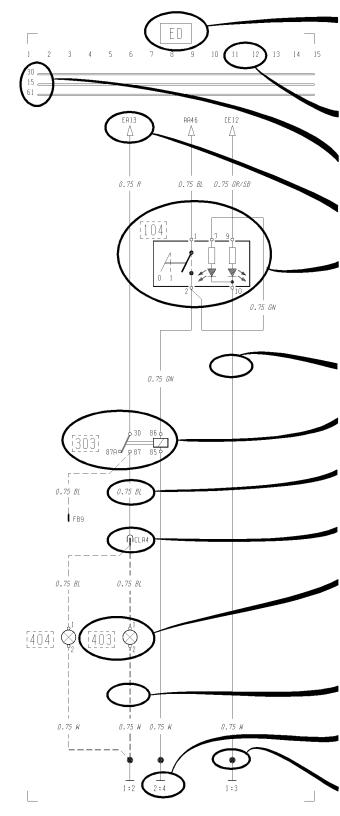
Example of wiring diagram
Refer to the list of contents for the designation of the circuit diagram. If the circuit diagram designation is boxed in with broken lines this means that the circuit diagram is not standard on all market or vehicle models.
Seek column.
30 Voltage battery, kl.30.
15 Voltage with starting key in drive position, kl.15.
61 Voltage when alternator charges, kl.61.
Reference arrow (for circuit diagram EA, seek column 13).
Switch, comp. no. (104).
Single lines, cables.
Relay, comp. no. (303).
Cable area and colour (0.75 mm² blue).
Connector (CLA terminal 4).
Bulb, comp. no. (403)
A broken line box round the component number shows that the component is not standard on all markets or vehicle models.
If the line is broken this means the cable is not standard on all markets or vehicle model.
Earth connection point no: 2. and earth terminal no: 4. (see diagram Earth Connections).
Joint sleeve.
T3009608
2
Group 37 Wiring diagram FL6 |
Examples of symbols on wiring diagram |
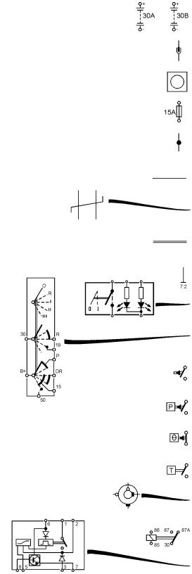
Examples of symbols on wiring diagram
Battery
Connector
Junktion
Fuse
Joint sleeve
Cable
Twisted cables
Conductor on circuit card
Earth connection and cable
Switch
Switch, starting switch
Closing contakt
Closing contakt, pressure-regulated
Break contakt, temperature-regulated
Closing contakt, time-regulated
Slip contakt, horn
Relay
Relay with internal circuit diagram
T3009609
3
Group 37 Wiring diagram FL6 |
Examples of symbols on wiring diagram |
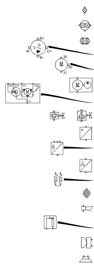
Bulb
Bulb, full beams and dipped beams
Bulb, tail light
Alternator
Starter motor
Washer motor
Windscreen wiper motor
Solenoid valve with diode
Pressure sensor
Temperature sensor
Level sensor
Starting heater
Cigarette lighter
Horn
Rheostat
Buzzer
Loudspeaker
T3009610
4
Group 37 Wiring diagram FL6 |
Component wiring diagram index |
|
Component wiring diagram index |
AA |
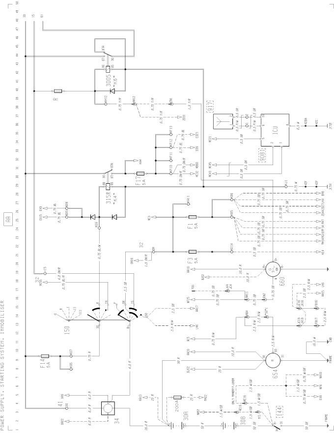
Power supply, starting system, immobiliser ..................................................................... |
AC |
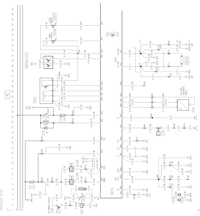
Vehicle ECU ..................................................................................................................... |
BJ |
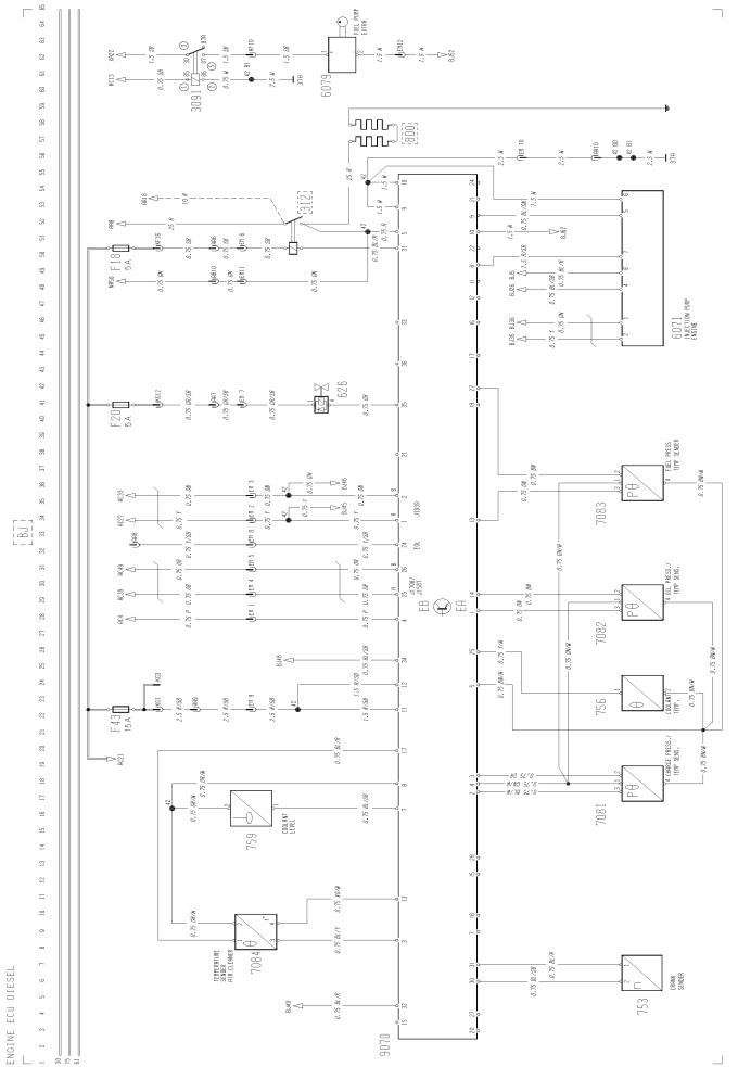
Engine ECU, DIESEL ...................................................................................................... |
BM |
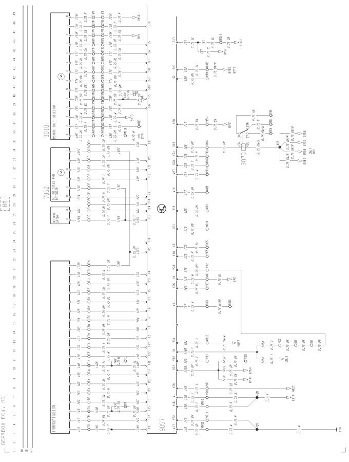
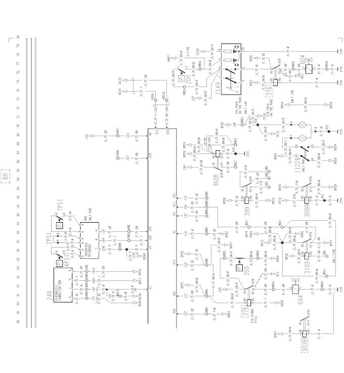
Gearbox ECU, MD3060P5/MD3560P5 ........................................................................... |
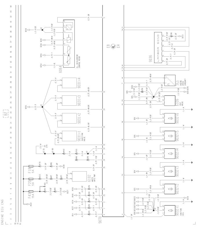
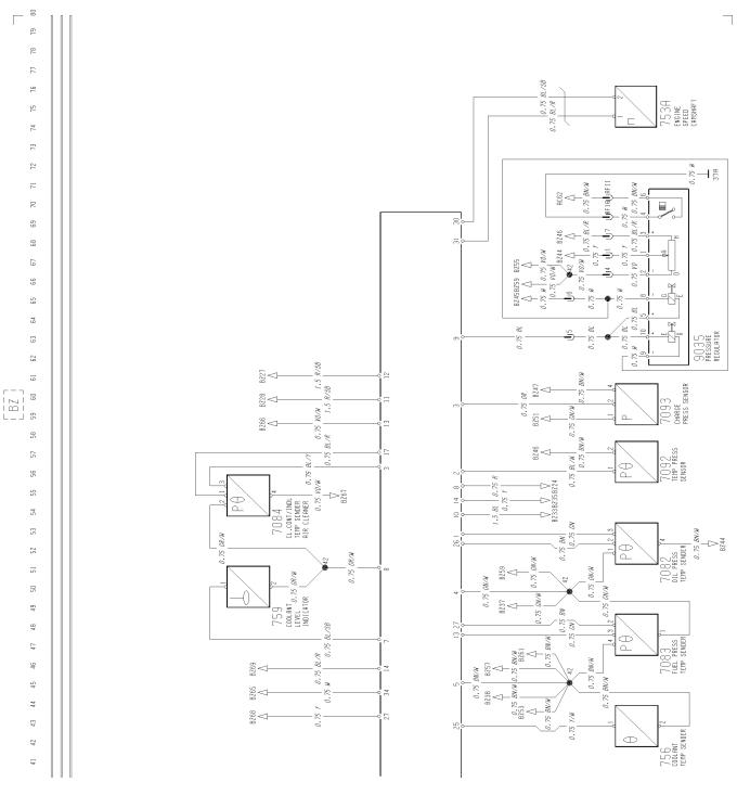
BZ |
Engine ECU, CNG ........................................................................................................... |
CE |
Head light, parking light, DRL .......................................................................................... |
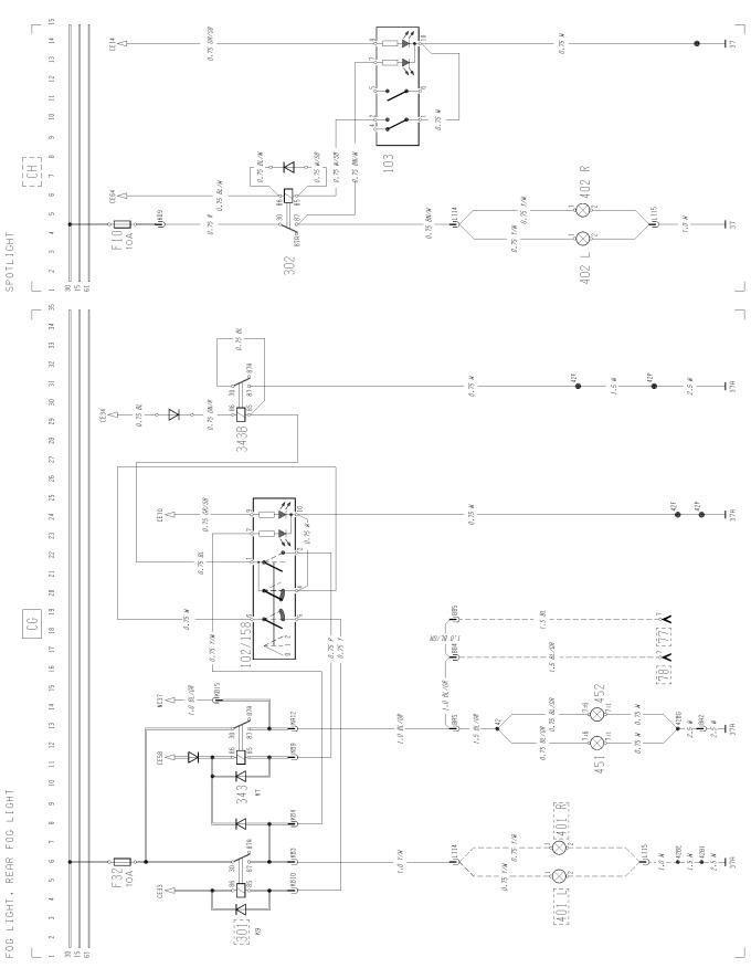
CG |
Fog light, rear fog light ..................................................................................................... |
CH |
Spot light ......................................................................................................................... |
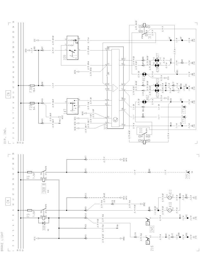
CK |
Brake light ........................................................................................................................ |
CN |
Direction indicator, hazard warning light .......................................................................... |
EA |
Reversing light, reversing warning alarm ......................................................................... |
ED |
Loading light/fifth wheel light ........................................................................................... |
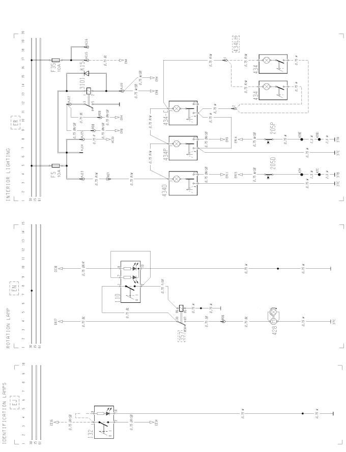
EJ |
Identification lamps .......................................................................................................... |
EN |
Rotating warning light ...................................................................................................... |
ER |
Interior lighting ................................................................................................................. |
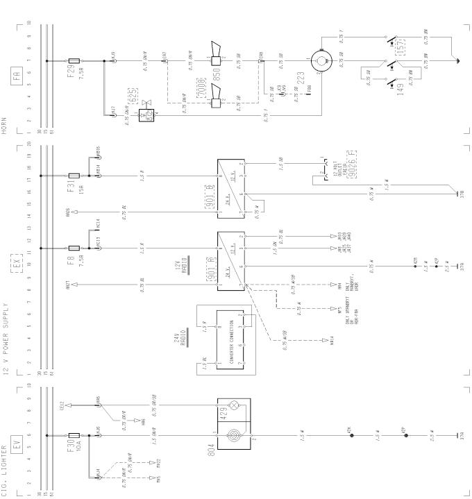
EV |
Cigarette lighter ............................................................................................................... |
EX |
12 V power supply ........................................................................................................... |
FA |
Horn ................................................................................................................................. |
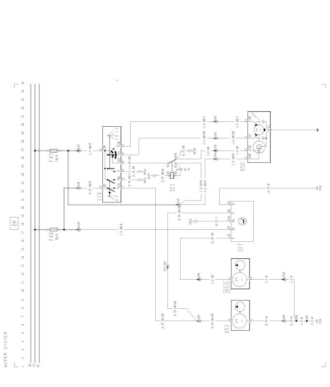
GA |
Wiper, washer .................................................................................................................. |
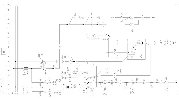
HA |
Climate unit ...................................................................................................................... |
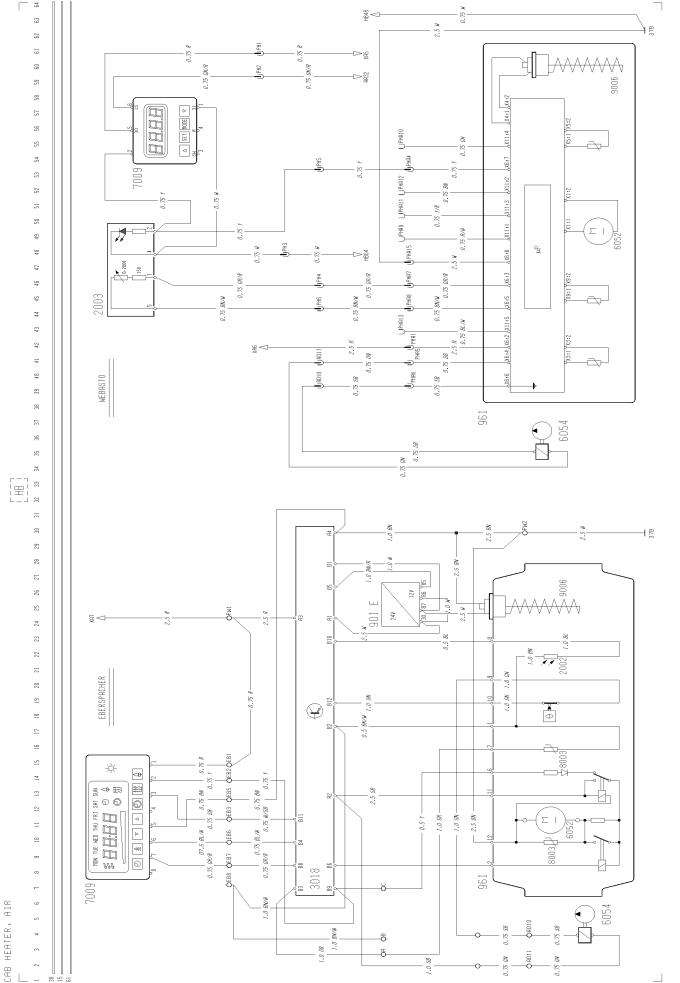
HB |
Cab heater, air ................................................................................................................. |
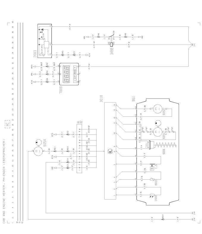
HC |
Cab and engine heater, PH-ENGCA (EBERSPÄCHER) ................................................. |
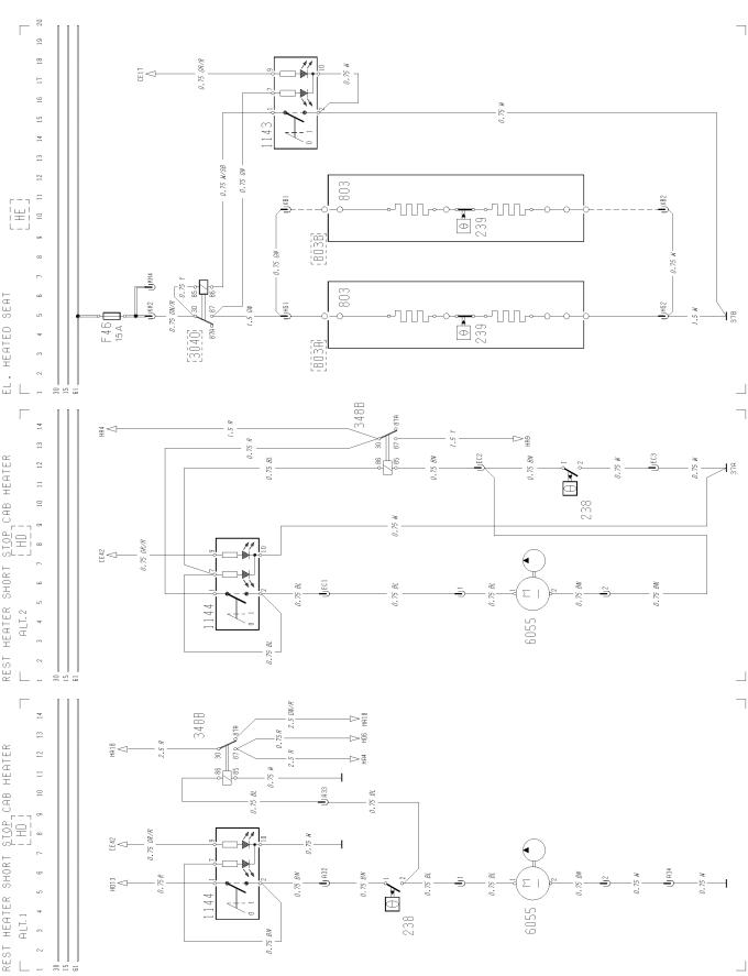
HD |
Rest heater, short stop cab heater .................................................................................. |
HE |
Electrically heated seat .................................................................................................... |
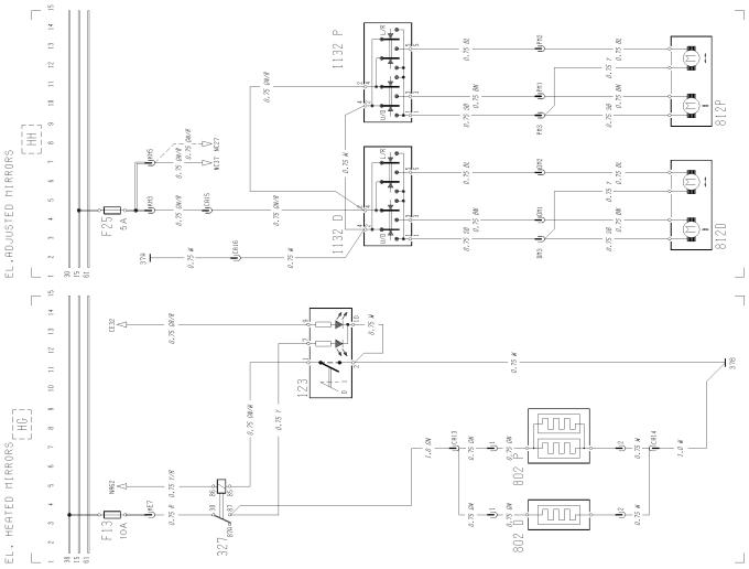
HG |
Electrically heated mirrors ............................................................................................... |
HH |
Electrically operated mirrors ............................................................................................ |
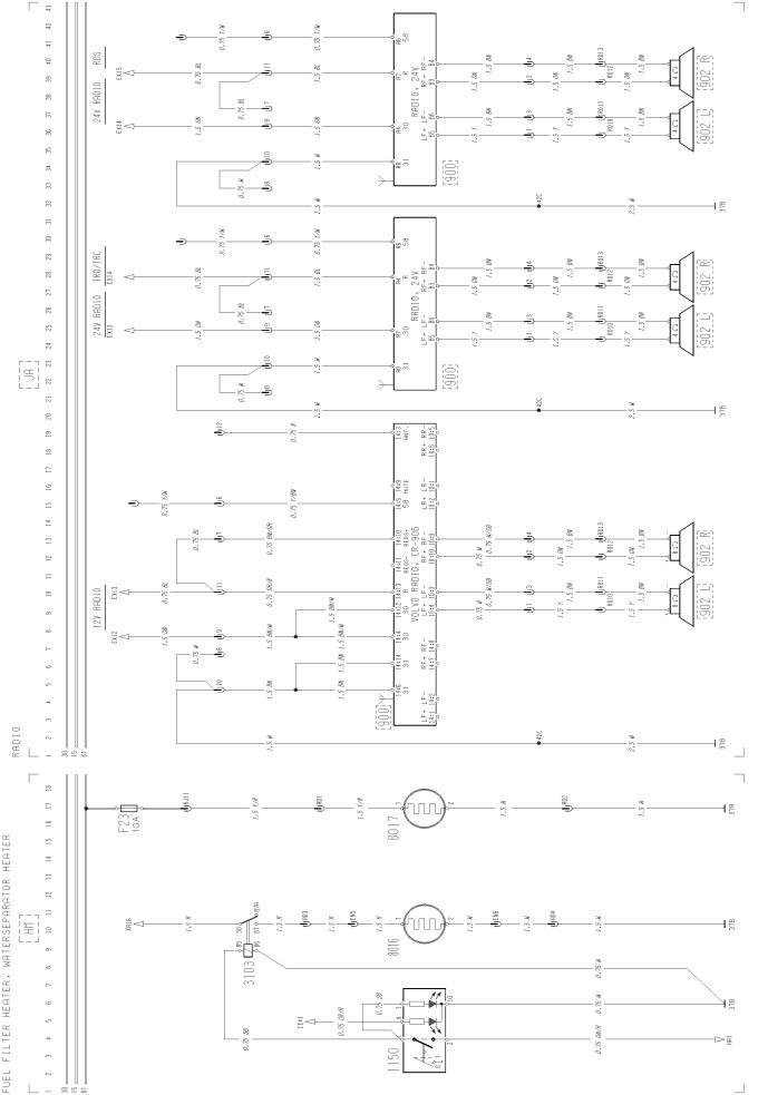
HM |
Fuel filter heater, water separator heater ......................................................................... |
JA |
Radio ............................................................................................................................... |
KA |
Electrically operated window winders .............................................................................. |
KE |
SRS, air-bag .................................................................................................................... |
KH |
Central locking CHID -B276335 ....................................................................................... |
KH |
Central locking CHID B276336- ....................................................................................... |
LD |
Power take-off or KOBLAM .............................................................................................. |
LE |
Power take-off and KOBLAM ........................................................................................... |
LG |
Differential lock ................................................................................................................ |
LK |
Automatic gearbox ........................................................................................................... |
page 7 page 8 page 10 page 12 page 14 page 16 page 17 page 17 page 18 page 18 page 19 page 19 page 20 page 20 page 20 page 21 page 21 page 21 page 22 page 23 page 24 page 25 page 26 page 26 page 27 page 27 page 28 page 28 page 29 page 30 page 30 page 31 page 31 page 32 page 32 page 33
5
Group 37 Wiring diagram FL6 |
Component wiring diagram index |
MA MF MF MG MG MH MH MV NA NA NC NF NZ OA PA RA XA XD ZA ZB ZB ZD ZD
Bogie lift, A-ride ...............................................................................................................
Air suspension, 4x2/6x2, RIGID, E-MEDIUM CHID-B344350 .........................................
Air suspension, 4x2/6x2, RIGID, E-MEDIUM CHID B344351– .......................................
Air suspension, 4x2, TRACTOR CHID-B344350 .............................................................
Air suspension, 4x2, TRACTOR CHID B344351– ...........................................................
Air suspension, 4x2, RIGID, L-H MEDIUM CHID-B344350 .............................................
Air suspension, 4x2, RIGID, L-H MEDIUM CHID B344351– ...........................................
Air-dump ..........................................................................................................................
Instrument LHS module CHID-B356223 .........................................................................
Instrument LHS module CHID B356224– ........................................................................
Instrument RHS module ..................................................................................................
Tachograph ......................................................................................................................
Instrument center module ...............................................................................................
Basic ABS, D-version ......................................................................................................
Headlight adjust ...............................................................................................................
Taillift ................................................................................................................................
Extra fuse block, key switch relay ....................................................................................
Extra connection body builder .........................................................................................
Earth connections ............................................................................................................
Earth connections CHID-B356223 ..................................................................................
Earth connections CHID B356224– ................................................................................
ADR battery main switch, current limiter CHID-B340450 ................................................
ADR battery main switch, current limiter CHID B340451– ..............................................
page 34 page 35 page 36 page 37 page 38 page 39 page 40 page 41 page 42 page 43
page 44 page 45 page 46 page 48 page 50 page 50 page 51 page 52 page 54 page 56 page 58 page 60 page 61
6
Group 37 Wiring diagram FL6 |
Component wiring diagrams |
Component wiring diagrams
T3017175
7
Group 37 Wiring diagram FL6 |
Component wiring diagrams |
T3017176
8
Group 37 Wiring diagram FL6 |
Component wiring diagrams |
T3017177
9
Group 37 Wiring diagram FL6 |
Component wiring diagrams |
10 |
T3017178 |
|
11
Group 37 Wiring diagram FL6 |
Component wiring diagrams |
T3015456
12
Group 37 Wiring diagram FL6 |
Component wiring diagrams |
T3015457
13
Group 37 Wiring diagram FL6 |
Component wiring diagrams |
T3015458
14
Group 37 Wiring diagram FL6 |
Component wiring diagrams |
T3015459
15

Group 37 Wiring diagram FL6 |
Component wiring diagrams |
16 |
T3017179 |
|
Group 37 Wiring diagram FL6 |
Component wiring diagrams |
T3015461
17
Group 37 Wiring diagram FL6 |
Component wiring diagrams |
T3013872
18
Group 37 Wiring diagram FL6 |
Component wiring diagrams |
T3013873
19
Group 37 Wiring diagram FL6 |
Component wiring diagrams |
T3013874
20
Group 37 Wiring diagram FL6 |
Component wiring diagrams |
T3017180
21
Group 37 Wiring diagram FL6 |
Component wiring diagrams |
T3013876
22
Group 37 Wiring diagram FL6 |
Component wiring diagrams |
T3017181
23
Group 37 Wiring diagram FL6 |
Component wiring diagrams |
24 |
T3017182 |
|
Group 37 Wiring diagram FL6 |
Component wiring diagrams |
T3013879
25
Group 37 Wiring diagram FL6 |
Component wiring diagrams |
T3017183
26
Group 37 Wiring diagram FL6 |
Component wiring diagrams |
T3015464
27
Group 37 Wiring diagram FL6 |
Component wiring diagrams |
28 |
T3017184 |
|
 Loading...