

Page 1

Driver’s Handbook
This is a complete Driver's Handbook
with all the information that can exist
in our chassis unique handbooks.
The information in the chassis unique
handbooks is steered on variants and
its content varies. This can cause
duplicated information in this complete
handbook, which can make it difficult to
read correctly. It is only intended for
internal use.
From build week 937 each truck has
its unique handbook which is possible
to order at [email protected].
FM, FH
Page 2
DEAR VOLVO OWNER
THANK YOU FOR CHOOSING VOLVO.
This vehicle binder describes the driving and care of your truck and instructions for the
tachograph. It also contains documents such as the Warranty book, Volvo Action Service card
and Driver service documents.
In order for your truck to retain its high safety, reliability and long life, we recommend that
you heed our advice regarding the driving and care of your vehicle.
If there is anything else you wonder about concerning service, maintenance, oils or the care of
your truck or your are missing some documentation in the binder, please contact your dealer.
Additional useful information about your truck and its functions can be found online:
http://www.volvo.com
The specifications and illustrations in this binder are not binding and we reserve the right to
change them without prior information.
©1998 Volvo Trucks AB, Gothenburg.
Reproduction of the contents of this vehicle binder, wholly or in part, is prohibited by law
without written permission from Volvo Trucks AB.
The prohibition covers all forms of reproduction, through printing, copying, recording on tape,
etc.
Page 3

The following levels of notification and warning are used in this binder.
Note! Indicates a situation, use or circumstance that should be emphasised.
Important! Indicates a situation, use or circumstance that is important to be aware of to avoid personal
Caution! Indicates a potentially dangerous situation that, unless avoided, may lead to minor or moderate
Warning! Indicates a potentially dangerous situation that, unless avoided,may lead to death, serious
Danger! Indicates a potentially dangerous situation that, unless avoided,will lead to death or serious
injury or damage to the product.
personal injury or damage to the product.
personal injury or damage to the product.
personal injury.
Page 4

Symbols
The following symbols may be found on your truck.
The meaning of the symbols is as follows:
Use protective goggles Read information in the driver's binder
Keep out of reach of children Corrosive
Avoid sparks or naked flame Explosive
Page 5

Table of Contents
Introduction................................................... 1
LVD system................................................. 1
EBS.............................................................. 1
Air suspension.............................................. 1
Booster......................................................... 2
Dynafleet...................................................... 2
Running in...................................................... 4
Starting and stopping.................................... 5
Starting instructions..................................... 5
Starting instructions..................................... 5
Start the truck............................................... 5
Stopping the truck........................................ 6
Stopping the truck........................................ 6
Stopping the truck........................................ 6
Parking......................................................... 7
Clutch........................................................... 7
Keys............................................................. 7
Start the engine............................................ 8
Warming up............................................... 11
Change idling speed................................... 11
Fuel heater.................................................. 12
Instruments and controls............................ 13
Overview.................................................... 13
Gauges........................................................ 17
Symbols...................................................... 19
Lighting and headlamps............................. 22
Windscreen wipers..................................... 25
Rain sensor................................................. 25
Parking brake............................................. 26
Trailer brake............................................... 29
Electric trailer brake................................... 29
Air suspension............................................ 30
Information display..................................... 33
General, about the display.......................... 33
The first that is shown................................ 34
General, about messages............................ 34
Information messages................................ 35
Warning messages..................................... 35
Stop message.............................................. 36
Alarm, warning and information
symbols...................................................... 36
Status symbols........................................... 40
Other Symbols........................................... 41
Menu structure........................................... 42
Show menus............................................... 45
Step between the menus............................. 45
Change a setting......................................... 45
Temperature, outside.................................. 47
Temperature, engine oil............................. 47
Temperature, gearbox................................ 47
Voltmeter/Ammeter................................... 47
Gear position.............................................. 48
Pressure, primary tank............................... 48
Fuel consumption....................................... 48
Leg data...................................................... 49
Remaining fuel........................................... 49
AdBlue....................................................... 49
Trip meter................................................... 50
Average speed............................................ 50
Estimated time of arrival............................ 51
Time and Date............................................ 51
Alarm clock................................................ 52
Driving/rest time........................................ 53
Black Panel................................................ 53
Backlight.................................................... 53
Favourite Display, setting.......................... 54
Night/Day................................................... 56
Vehicle Messages....................................... 56
Tyre pressure.............................................. 56
Set wheel ID............................................... 57
Set reference pressure................................ 57
Reset........................................................... 58
ATS............................................................ 58
Start regeneration....................................... 58
Abort regeneration..................................... 59
Activate/Deactivate ATS........................... 59
System conditions...................................... 59
Soot/ash level............................................. 60
Programming, p-heater timer..................... 60
Reset, p-heater timer.................................. 61
Language.................................................... 61
Units........................................................... 61
Page 6

Table of Contents
Time/Date.................................................. 62
Display lighting.......................................... 63
Change password....................................... 63
Traction control.......................................... 64
DAS............................................................ 64
LCS............................................................ 64
Fleet limits................................................. 64
Ammeter sensor calibration....................... 66
Fleet ID...................................................... 66
Trailer detection......................................... 67
Day running lights automatic..................... 68
Draining/priming........................................ 68
Fault diagnostics........................................ 69
Instrument panel cluster self test................ 70
Part number................................................ 71
Vehicle data............................................... 72
Vehicle ID.................................................. 72
Total value................................................. 73
Trip data..................................................... 73
Reset trip data............................................ 74
Password.................................................... 74
Service reminder........................................ 75
Estimated lining wear................................ 77
Monitoring of the wheel brakes................. 78
High brake temperature warning............... 78
Resetting fault codes.................................. 78
Position and content................................... 80
Display....................................................... 81
Display control stalk.................................. 82
General, about messages............................ 82
Information messages................................ 82
Warning messages..................................... 83
Stop message.............................................. 83
Acknowledge messages............................. 83
Alarm, warning and information
symbols...................................................... 84
Status symbols........................................... 88
Other Symbols........................................... 89
Gear position.............................................. 89
Temperature, outside.................................. 89
Engine oil pressure..................................... 89
Temperature, engine oil............................. 89
Voltmeter/Ammeter................................... 90
Fuel consumption....................................... 90
Leg data...................................................... 90
Remaining fuel........................................... 91
AdBlue....................................................... 91
Trip meter................................................... 91
Average speed............................................ 92
Driving/rest time........................................ 92
Time and Date............................................ 92
Menu structure........................................... 93
Black Panel................................................ 93
Night/Day................................................... 94
Backlight.................................................... 94
Contrast...................................................... 94
Language.................................................... 94
Units........................................................... 95
Time/Date.................................................. 95
Program...................................................... 96
Reset........................................................... 96
Traction Control......................................... 97
Day Running Light.................................... 97
Draining/priming........................................ 97
Fault diagnostics........................................ 97
Part number................................................ 99
Calibration ID............................................ 99
Service reminder........................................ 99
Numeric language, general...................... 102
Display control stalk................................ 102
Text strings............................................... 103
Stop message............................................ 103
Change language...................................... 104
Menus, general......................................... 104
Password-protected menus....................... 104
Menus available when driving................. 104
Menus with stationary vehicle................. 108
Numerical translation table...................... 116
Driving........................................................ 127
Driving hints............................................ 127
Hill start aid.............................................. 130
Reversing camera..................................... 131
Reversing Warner.................................... 133
Traction Control System (TCS)............... 133
Front wheel drive..................................... 135
Page 7

Table of Contents
Differential lock....................................... 136
Differential lock....................................... 140
Differential locks..................................... 143
Automatic engagement of the
differential lock (DLC – Diff Lock
Control).................................................... 146
Auxiliary brakes....................................... 148
Brake Blending........................................ 152
ABS.......................................................... 152
ESP — Electronic Stability Program....... 153
Control of engine torque.......................... 153
Brake lining wear equalisation................. 154
Panic braking function............................. 154
Manual gearbox....................................... 154
Hydraulic bogie lift.................................. 158
Bogie........................................................ 159
Tridem...................................................... 165
Steered rear axle....................................... 168
Cruise control........................................... 169
Constant engine speed control................. 170
Lane Keeping Support............................. 170
Lane Change Support............................... 172
Driver Alert Support................................ 174
Power take-off.......................................... 176
High range lock-up.................................. 179
High range lock-up.................................. 181
Tying down the truck on a ferry.............. 182
Ride height memory................................. 187
ADR............................................................ 193
General..................................................... 193
Turn off the power................................... 193
Turn on the main switch.......................... 194
Turn on power for 20 minutes................. 195
Adaptive cruise control............................. 197
General..................................................... 197
Engaging ACC......................................... 198
Disengage ACC....................................... 199
Inactivate ACC......................................... 199
Change speed........................................... 199
Change the time gap................................. 200
When the truck itself adjusts the speed.... 201
When the vehicle must be braked
manually................................................... 202
Brake protection....................................... 202
Driving at low speed................................ 203
If the ACC does not work........................ 204
Powertronic................................................ 205
Powertronic, general................................ 205
Gear shifter............................................... 205
Buttons..................................................... 206
Display..................................................... 207
Driving programs..................................... 209
Automatic gear changing......................... 209
Kickdown................................................. 210
Manual gear changing.............................. 210
Select starting gear................................... 210
Autoneutral.............................................. 211
Brake interlock......................................... 211
Dual driver stations.................................. 212
Auxiliary brakes....................................... 212
Actions with gearbox malfunction........... 212
Reversing with loads................................ 212
Rocking free............................................. 213
Marshalling.............................................. 213
Idling speed.............................................. 213
Oil temperature........................................ 214
Retarder temperature................................ 214
Oil pressure.............................................. 215
Oil filter.................................................... 215
Checking the oil level.............................. 215
I-Shift.......................................................... 217
I-shift, general.......................................... 217
Gear selector............................................ 217
Buttons..................................................... 219
Display..................................................... 220
Program packages.................................... 222
Automatic shifting................................... 225
Manual shifting........................................ 228
Reverse gears........................................... 229
In case of gearbox malfunction................ 230
Starting on hills........................................ 230
Driving off road....................................... 231
Page 8

Clutch....................................................... 231
I-Shift.......................................................... 232
I-Shift, general......................................... 232
Program packages.................................... 232
Function description................................. 234
Gear shifter............................................... 236
Buttons..................................................... 238
Display..................................................... 239
Automatic gear change............................ 241
Manual gear changing.............................. 246
Reverse gears........................................... 247
Actions with gearbox malfunction........... 248
Fuel economy driving.............................. 248
Hill start................................................... 250
Driving on poor roads and in
difficult conditions................................... 251
Disengaging............................................. 251
Starting when stuck.................................. 251
Full VEB/VEB+ in manual mode............ 253
Extra down-changing for
maximum engine brake in low gears....... 253
Changing driving direction...................... 253
Driving with the gearbox-mounted
power take-off engaged............................ 253
Rocking to empty the platform................ 254
Driving on rollers..................................... 254
Loading and unloading............................. 255
General..................................................... 255
Ride height control................................... 255
Loading and unloading height memory... 258
Quick unloading....................................... 265
Using the air suspension with the
ignition turned off.................................... 267
Loading and unloading with the
main switch off........................................ 270
Fetch the swap body................................. 276
Leave the swap body................................ 281
Fetch a container...................................... 284
Deliver a container................................... 286
Load indicator.......................................... 287
Table of Contents
Exhaust cleaning........................................ 291
General..................................................... 291
Driving a truck with a Euro 4 or
Euro 5 engine........................................... 294
Filling with AdBlue................................. 297
Cleaning the AdBlue tank........................ 299
Diesel particulate filter............................. 299
Cab.............................................................. 303
Air suspension equipment........................ 303
Seats......................................................... 309
Adjusting the steering wheel.................... 313
Doors........................................................ 314
Central locking......................................... 316
Main switch.............................................. 318
Air conditioning ECC (Electronic
Climate Control)...................................... 318
Air conditioning MCC (Manual
Climate Control)...................................... 323
Climate control system HEAT................. 326
Cab heater PH-CAB................................. 328
Cab and engine heater PH-ENGCA......... 333
Rest heater SS-HEAT.............................. 341
Luggage compartment hatch.................... 343
Electrically operated sun roof.................. 344
Lighting.................................................... 344
Electrical power outlet............................. 351
Bunk bed.................................................. 351
Lower bunk.............................................. 352
Smoke detector......................................... 353
Tilt the cab............................................... 354
Mobile telephone, communication
equipment................................................. 359
Alarm on.................................................. 359
Alarm without motion detectors.............. 360
Alarm off.................................................. 361
Starting the assault alarm......................... 361
Switching off the assault alarm................ 362
Go into service mode............................... 362
To get out of service mode....................... 363
Assistance button..................................... 363
Page 9

Table of Contents
Refrigerator............................................... 364
Safety instructions.................................... 364
General..................................................... 364
Usage........................................................ 364
Starting the refrigerator............................ 365
Turning off the refrigerator...................... 365
Voltage protector..................................... 365
Tilting the cab.......................................... 366
Cleaning................................................... 366
Defrosting................................................ 366
Interior lighting........................................ 366
Fault tracing............................................. 367
Tips on saving energy.............................. 367
Technical specifications........................... 367
Fridge.......................................................... 368
Safety instructions.................................... 368
General..................................................... 368
Usage........................................................ 368
Starting the refrigerator box..................... 369
Switching off the refrigerator box............ 369
Voltage protector..................................... 369
Tilting the cab.......................................... 370
Cleaning................................................... 370
Defrosting................................................ 370
Fault tracing............................................. 370
Tips on saving energy.............................. 371
Technical specifications........................... 372
Alcolock...................................................... 373
Start up..................................................... 373
Restarting the vehicle............................... 375
Sharing a vehicle...................................... 376
Energy conservation................................. 380
Volume control........................................ 381
Language selection................................... 382
Dates........................................................ 383
General messages and errors.................... 383
Technical messages and errors................. 384
Radio/CD.................................................... 386
Safe Operation of the Radio..................... 386
Introduction.............................................. 386
General Overview.................................... 387
Main Functions........................................ 395
Tips and Tricks........................................ 405
Main Functions........................................ 405
Tips and tricks.......................................... 428
Telephone................................................... 430
Getting started.......................................... 430
Calling...................................................... 432
While making a call................................. 435
Managing messages................................. 436
Menus....................................................... 438
Measures with malfunctions.................... 443
Booster........................................................ 444
Booster..................................................... 444
Installation................................................ 444
Methods of use......................................... 444
Fuses........................................................ 444
Indicator lamps......................................... 444
Subwoofer controls and switch................ 445
Fault tracing............................................. 445
Dynafleet.................................................... 447
Dynafleet.................................................. 447
Technical description............................... 448
Controls.................................................... 450
Display..................................................... 452
Menus and symbols.................................. 453
Using the menus....................................... 454
Starting the system................................... 455
Shutting off the system — stand by......... 456
Transferring data...................................... 456
General..................................................... 457
Mail.......................................................... 457
Mail menu................................................ 458
General driving and resting times............ 459
Orders....................................................... 461
Logs.......................................................... 462
Driver coaching........................................ 464
Emergency & Assistance......................... 465
Tachograph download menu.................... 465
Page 10

Table of Contents
Settings..................................................... 467
System errors and warnings..................... 468
External equipment................................... 470
Roof air deflector, setting instructions..... 470
Short low cab FH..................................... 472
Long low cab FH..................................... 473
Globetrotter FH........................................ 474
Roof air deflector, setting instructions..... 476
Globetrotter XL FH.................................. 478
Roof air deflector, setting instructions..... 483
Short low cab FM..................................... 485
Long low cab FM..................................... 486
Globetrotter FM....................................... 487
Globetrotter LXL FM.............................. 488
Front mirror.............................................. 490
Ladder...................................................... 491
Side underrun guard................................. 492
Lower the spare wheel............................. 494
Raise the spare wheel............................... 495
Spare wheel retainer behind the cab........ 496
Turntable, general advice......................... 499
Couple the trailer...................................... 500
Moving the turntable................................ 502
Maintenance............................................... 504
General information................................. 504
Checks before driving.............................. 504
Checks when fuelling............................... 508
Changing wiper blades............................. 509
Replace the battery in the remote
control...................................................... 510
Changing bulbs........................................ 510
Engine wash............................................. 516
Washing the chassis................................. 516
Wash the cab............................................ 516
Polishing and waxing............................... 517
Care of upholstery.................................... 518
Paintwork damage.................................... 519
Care of aluminium rims........................... 521
Care of steel rims..................................... 521
Tools........................................................ 522
General information about oils and
greases...................................................... 523
Engine...................................................... 525
Fuel system.............................................. 530
Diesel fuel— quality and function........... 531
Changing fuel filter.................................. 536
Filter for fuel tank ventilation.................. 537
Priming the fuel system........................... 537
Draining the fuel tank.............................. 538
Changing filter......................................... 539
Drain the cooling system......................... 542
Service intervals....................................... 544
Anti-freeze............................................... 544
Fill with coolant in an empty system....... 545
Viscous fan............................................... 545
Electrically controlled fan........................ 545
Check the drive belts (Multi-V)............... 546
Working on the electrical system............. 546
Instructions for electrical welding........... 547
Connection of electrical accessories........ 548
Checking electrolyte level in batteries..... 549
Charge status............................................ 550
Specifications for the electrical system.... 551
Manual gearbox and I-shift...................... 552
Automatic gearbox................................... 559
Transfer gearbox...................................... 562
Driving front axle..................................... 566
Flywheel mounted power take-off........... 570
Compact retarder...................................... 571
Air drier, general...................................... 575
Checking the air drier............................... 576
Charging with air from an external
compressed air source.............................. 577
Brake lining.............................................. 577
Servo steering........................................... 578
Hydraulic pusher axle and trailing
wheel axle................................................ 579
Rear axle.................................................. 580
Rear axle with hub reduction................... 587
Tyres........................................................ 588
Changing wheels...................................... 593
Disc wheel for disc brakes....................... 600
Painting rims............................................ 601
Page 11

Table of Contents
Spare wheel in Combi-box....................... 602
Snow chains............................................. 602
Hydraulic bogie lift.................................. 603
Bodywork................................................. 603
Cab tilt pump............................................ 604
Central lubrication................................... 604
Changing air filter for air
conditioning system................................. 605
Refrigerant............................................... 606
Parking heater.......................................... 606
Chassis lubrication................................... 607
Type plates, location................................ 615
Fuses and relays......................................... 617
General..................................................... 617
Electrical distribution unit, left-
hand drive trucks...................................... 618
Electrical distribution unit, right-
hand drive trucks...................................... 619
Main fuses................................................ 620
In relay and fuse box................................ 622
To superstructure..................................... 626
If something happens................................ 628
Air suspension in locked mode................ 628
Airbag...................................................... 630
Warning signs and first-aid...................... 631
Fire extinguisher...................................... 631
Starting with starting cables..................... 632
Towing..................................................... 635
Back-up function...................................... 641
In case of gearbox malfunction................ 641
If the vehicle gets stuck............................ 642
Page 12

LVD system
The vehicle is equipped with software that registers
different types of information about the vehicle. The
information will be transferred to Volvo Trucks AB
and used in product development and fault tracing in
engines and vehicles. Information that is saved
concerns, among other things, speed, fuel consumption
and torque. Volvo Trucks AB and its authorised
workshops will make use of this information.
Questions concerning the use of this information can
be made to
Volvo Action Service.
.
EBS
generation 3 functions in a different way to
EBS
earlier braking systems. In previous braking systems a
particular pressure to the pedal gave a particular
pressure to the braking system. With
particular pressure on the pedal will give a particular
reduction of speed. The same depression of the pedal
gives the same reduction of speed, but the pressure to
the brake cylinders on the axles varies with the axle
load.
After changing loads, the first brake application can
feel strange, since the system must learn the new axle
loads.
adapts the braking pressure to the trailer so that
EBS
the trailer brakes to the same degree as the truck.
EBS 3
a
Introduction
1
Air suspension
This truck has full air suspension and thus has bellows
instead of leaf springs. The amount of air in the
bellows can be regulated, and determines the ride
height.
The air suspension is electronically controlled
(ECS, electronically controlled suspension)
maintains constant ride height irrespective of load
and
Page 13

2
weight and positioning. Ride height can also be
controlled manually, by using the control box.
In order for the air suspension to work, the pressure in
the air tanks must be greater than 8 bar
suspension is activated after starting or when the
parking brake is released or when the air suspension
control box is used. None of the suspension functions
will work before the system has been started by one of
these methods.
This truck has rear air suspension and thus has bellows
instead of rear leaf springs. The amount of air in the
bellows can be regulated, and determines the ride
height.
The air suspension is electronically controlled
(ECS, electronically controlled suspension)
maintains constant ride height irrespective of load
weight and positioning. Ride height can also be
controlled manually, by using the control box.
In order for the air suspension to work, the pressure in
the air tanks must be greater than
suspension is activated after starting or when the
parking brake is released or when the air suspension
control box is used. None of the suspension functions
will work before the system has been started by one of
these methods.
Introduction
8 bar
. The air
and
. The air
Booster
Volvo's multi-channel booster VA 400.8 is a premiumclass eight-channel power amplifier for motor
vehicles. If has integrated cross-overs for all channels
and a number of sub-woofer controls for individual
adjustments. The booster is factory installed and preset
to give a natural and well balanced sound.
Dynafleet
Dynafleet
with vehicle planning, message handling and
automatic reporting of vehicle status and driver times.
is a system for transport planning combined
Page 14

The driver communicates continually with the office.
The traffic officer in the office can direct the vehicle to
various places for various missions. The driver can
send messages to other drivers, to the office or
privately. Contact between the driver and the office
means that much of the order administration can be
administered in a simple way and more effective
manning of transport is achieved. Communication with
the central office takes place via the GSM mobile
phone network.
The system collects information from the tachograph
and the engine control unit.
driver with information about the vehicle and driving
activities. This makes it possible to have a better
transport administration and follow-up of the running
costs of the vehicle, the work contribution of the driver
and how economically the driver drives.
The section “Design and function” describes the most
basic functions that all drivers must be familiar with.
In the “System management” section there is a system
overview and a description of how the system is
started. The remaining sections describe the system
functions in more detail.
Dynafleet
provides the
Introduction
3
Page 15

4
Running in
Drive carefully during the truck's first
the engine speed within the green area on the
tachometer.
Do not drive fast with a heavy load. Keep an eye on
the warning lamps!
REMEMBER to leave the truck for warranty service
after 4 weeks operation or
depending on which occurs first. (With vehicles
manufactured in Europe the guaranteed service is only
offered if they have automatic transmission, fly-wheel
mounted power take-off or all-wheel drive)
All Volvo engines are test driven before delivery. This
means that we have control of all fits and decline all
responsibility for any damage caused by careless
driving.
10 000 km
5 000 km
mileage,
. Keep
Note!
During the first
power train shall not be subject to
heavy loads, since this can cause
abnormally high temperatures in
gears and drives.
1 500 km
, the truck's
Page 16
Starting and stopping
Starting instructions
Put the gear selector in the neutral or tilted position or
the engine will not start.
When the air pressure to the gearbox is too low, a
warning will be displayed automatically. An icon will
appear on the display at the same time as the
information lamp comes on. Wait until the lamp has
gone out before driving off.
Starting instructions
Put the gear shift lever in the neutral or tilted position,
otherwise the engine will not start.
If the air pressure to the gearbox is too low, a warning
will be shown automatically in the display. An icon
will appear in the display at the same time as the
information lamp lights. Wait until the lamp has gone
out before driving off. Then move the gear shift lever
to A, M or R to be able to drive.
5
Information lamp
Symbol for low air pressure to
gearbox
J3014466
Information lamp
Start the truck
To start the truck, select neutral position N and turn
the key. The truck cannot be started if the gear shift
lever is in the A, M or R position.
J3008849
Icon for low air pressure to gearbox
Page 17
6
Starting and stopping
Stopping the truck
When the vehicle is stationary:
• Apply the parking brake.
• Move the gear selector to N, neutral.
• Switch off the engine.
Stopping the truck
When the vehicle is stationary:
• Apply the parking brake.
• Move the gear shift lever to N, neutral.
• Switch off the engine.
Caution!
Always apply the parking brake
and put the gear selector in N
when the vehicle is parked or
whenever the driver leaves the
driver position.
Caution!
Always apply the parking brake
and move the gear shift lever to N
when the truck is parked or if the
driver must leave the cab for
some reason.
Stopping the truck
When the vehicle is stationary:
• Apply the parking brake.
• Move the gear shift lever to N, neutral.
• Switch off the engine.
Caution!
Always apply the parking brake
and move the gear shift lever to N
when the truck is parked or if the
driver must leave the cab for
some reason.
Page 18
Starting and stopping
Parking
Since the gearbox does not have a “parking position”
the truck's parking brake must always be used when
the driver has parked the vehicle and left the cab. For
longer stops and when the driver leaves the driver's
seat, the gear shift lever must also be moved to
position N.
Clutch
The clutch is of the dry disc type, i.e. no torque
converter. Therefore, never pull away in high gears by
slipping the clutch. If the clutch overheats, the
information lamp will light and a symbol will appear
in the display.
If the information lamp lights when the vehicle is
started and the truck is already moving, continue to
drive.
If the information lamp lights when the vehicle is
started and the truck is stationary, move the gear shift
lever to the A or R position and let the engine run at
idle until the light goes out.
When starting in manual mode, choose 1st gear to
avoid straining the clutch.
7
J3014466
J3008835
Caution!
Never hold the vehicle stationary
on an uphill slope by using the
accelerator pedal. The clutch
could overheat, which could
cause it to fail.
Keys
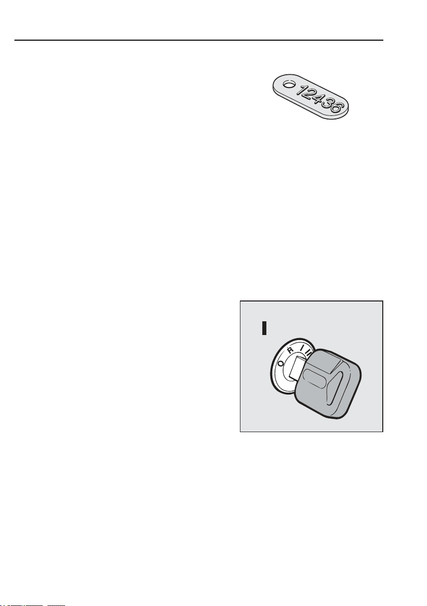
All keys have the same number as on the separate
number tag. Remove the number tag from the key ring,
to ensure that no unauthorized person can see the tag.
Put or tape the tag in a safe place (there is self
adhesive tape on the back).
Note!
Do not have other keys on the same
key-ring as the ignition key. The
ignition key contain electronics
which can be affected.
Page 19
8
Starting and stopping
Start the engine
1 Switch on the main switch.
2 Check that
• the parking brake is applied
• the gear lever is in neutral.
• auxiliary brakes are in position 0
3 Turn the starter key to drive position
J3014615
Number tag. Remove the number tag
from the key-ring and store it in a
safe place.
J7008414
Page 20

Starting and stopping
4 The display will show the oil level in the engine. If
the engine has been running during the previous 20
minutes nothing will be shown. The value shown
under the graph is the difference between the engine
max and min oil volumes.
5 If the truck has air bags, the symbol for this is shown
on the display
9
Note!
If the key is turned directly from off
position to start position, there will
be a delay of about 1 second before
the starter motor is activated. During
this time the starter motor shows no
response as it is activated via EMS.
When starting from radio position
there is however no such delay.
Note!
If the key is turned directly from the
off to the starting position, it is not
certain that the automatic radio code
entry will function. To avoid this
problem, wait a short while in the
drive position before starting.
6 Check that all the instrument panel lamps are
working
J3008842
Page 21
10
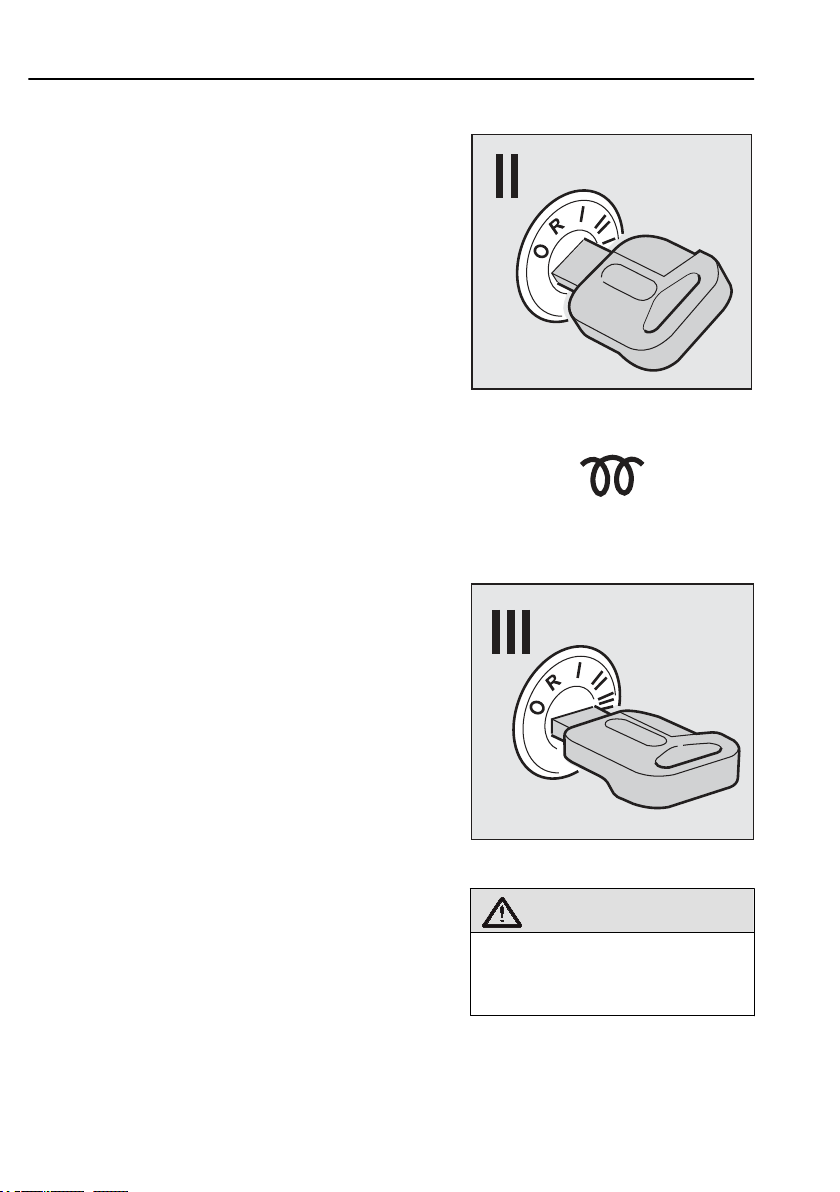
7 If the engine has air intake heating, turn the key to
the air intake heating position and release the key
8 Wait until the pre-heating symbol goes out
9 Start the engine
Run the starter motor by turning the key to the start
position. If the engine does not start, the starting
attempt will be automatically shut off after 15 seconds.
A new attempt can be made if the key is first turned
back to 0 position and then to the start position.
If the overheating protection is triggered, a message is
shown on the display when the overheating protection
is activated. The message shows how long the starter
motor must be allowed to cool before it will be
possible to try to start the truck again, usually 10–15
minutes.
Starting and stopping
J3015694
J0008226
Preheating symbol
J3015695
10 Hold down the brake pedal for a few seconds to
enable the cruise control. The air suspension is
Warning!
Do not use start gas. An
explosion can cause considerable
damage.
Page 22
Starting and stopping
activated first after the parking brake is released or if
the air suspension control box is used.
If the temperature of the coolant is below 50°C when
the engine is started the engine speed will be limited to
1000 rpm
Warming up
Warm the engine up by driving with low engine speed
rather than running the engine while stationary. Avoid
revving up excessively and high engine speed.
After starting let the clutch out in order to warm up the
gearbox. The oil pump in the gearbox will begin
working and will quickly attain working temperature.
Change idling speed
The preset idle speed can be altered between
and
speed is normally
temporarily, i.e. when the PTO is in use, see section
"Constant engine speed control")
Conditions:
• The temperature of the coolant should exceed 50°C.
• The truck should remain stationary with the engine
for 15 seconds
550 rpm
650 rpm
idling (the accelerator must not be depressed) when
the adjustment is begun.
. When the truck is delivered, the idle
600 rpm
. (To change the idle speed
11
Note!
It is especially important that the
gearbox should be warmed up if it
the outside temperature is below
0°C.
Procedure:
1 Depress the brake pedal. The brake pedal should
be depressed during the entire procedure.
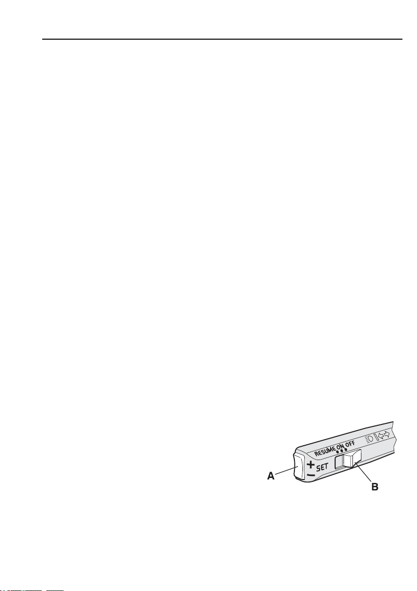
2 Hold B in RESUME for three seconds.
3 Release B.
Idling speed will fall to the lowest possible
setting.
4 Adjust engine speed with SET (A).
5 Hold B in RESUME and at the same time depress
SET (A) for more than three seconds.
J0008305
Page 23
12
6 Release the switches.
7 Release the brake pedal.
If an error has been made during the adjustment
sequence the previous idling speed will be retained.
Starting and stopping
The new idling speed is set.
Fuel heater
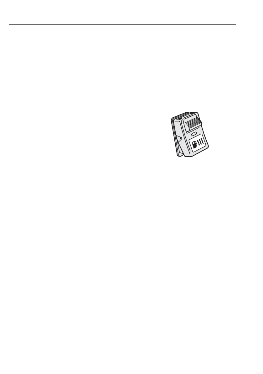
Trucks equipped with
heated fuel lines which prevents the fuel from freezing
on its way to the engine.
extreme cold conditions to heat the fuel before starting
and while driving.
Activate the function by pressing in the switch in the
instrument panel. For the fuel to be warmed up before
starting, the function should be activated at least
5 minutes
Fuel Heater
pressed in, but the effect varies according to needs.
The function is switched off automatically when the
ignition is switched off.
before starting.
is active as long as the switch is held
Fuel Heater
Fuel Heater
have electrically
is used in
J192368
Switch for fuel heater
Page 24
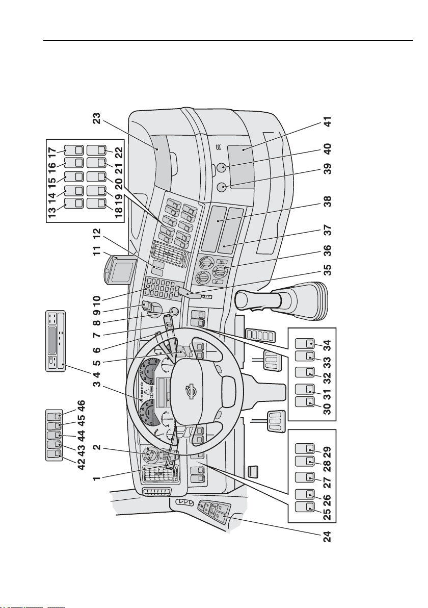
Overview
Instruments and controls
13
J0010472
Page 25
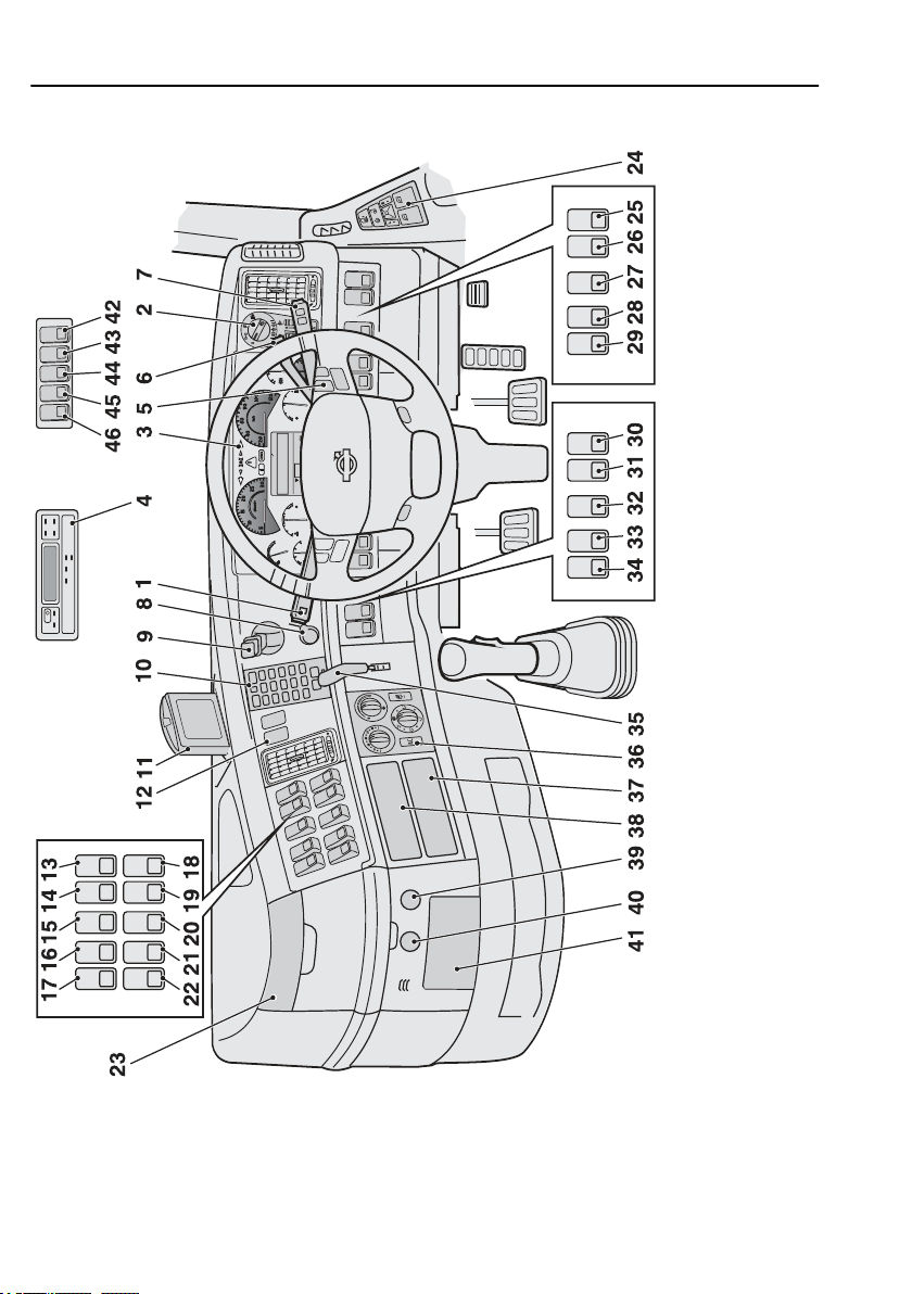
14
Instruments and controls
J0010474
Page 26

Instruments and controls
1 Stalk for direction indicators, cruise control and engine speed control
2 Lighting control panel
3 Instrument with driver information display
4 Tachograph
5 Buttons for radio and telephone
6 Stalk for auxiliary brake
7 Stalk for windscreen wiper and driver information display
8 Blocking valve
9 Parking brake
10 Phone
11
Display for
Dynafleet
and reversing camera
15
12
13 - 22 Switch for reversing lights
23 Bottle holder
24 Door control panel
Buttons for
Switch for rotating beacon
Switch for reversing camera
Switch for parking heater
Switch for inner lighting
Switch for auxiliary brake
Switch for bogie lift
Switch for differential lock
Switch for
Switch for front wheel drive
Switch for
Switch for switching off movement sensor
Switch for
Switch for panic alarm
Dynafleet
ADR
cornering lights
Volvo Action Service
and integrated telephone
Page 27

16
25-29 Switch for working lights
30-34 Switch for fifth wheel
Instruments and controls
Switch for hydraulic kit or body
Switch for container lock
-outlet
OBD
Switch for
Switch for cab tilt
Switch for power take-off
Switch for
35
36 Climate control system
37
38
39
40
41 Ashtray
42 Roof sign
43 Electric roof hatch
44 Thermostat
45 Spotlights
46 Switch for cab interior lighting
Stalk for trailer brake or switch for trailer brake,
Radio, tachograph or
Radio or
USB
Electrical outlet
spotlights
Emergency Assistance Button
Dynafleet
Dynafleet
port
12 V (Max 10 A)
or extra equipment
EBS
Page 28
Instruments and controls
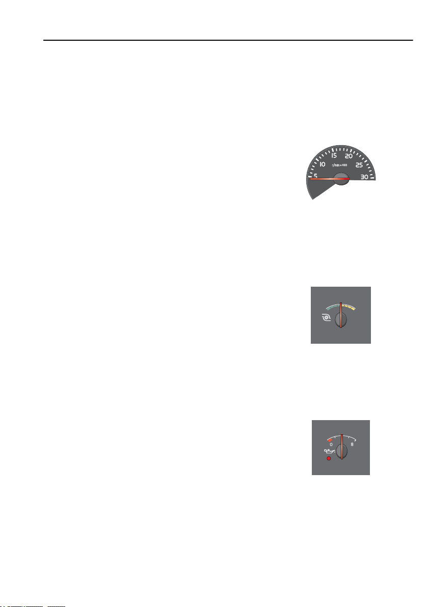
Gauges
Tachometer
The tachometer is divided into three fields indicated
by LEDs: Green LEDs, red LEDs and a field between
them with extinguished LEDs.
Use the green zone for normal driving.
Use the extinguished zone for engine braking.
Never let the engine go into the red zone.
Charge pressure gauge
To give good fuel economy, the needle should stay
still when driving on a flat road.
17
J201128
Oil pressure gauge
If the warning lamp lights up stop immediately and
switch the engine off! Investigate the cause. If the
lamp lights while the engine is running, an acoustic
alarm sounds. In addition the STOP lamp lights and a
warning message is shown on the display.
When driving with the engine at normal temperature,
the needle should stay between 3 and
550 kPa). The oil pressure may drop when the engine
is idling. This is not dangerous if the oil pressure
increases again when engine speed increases.
5.5 bar
(300–
J201133
J201132
Page 29
18
Instruments and controls
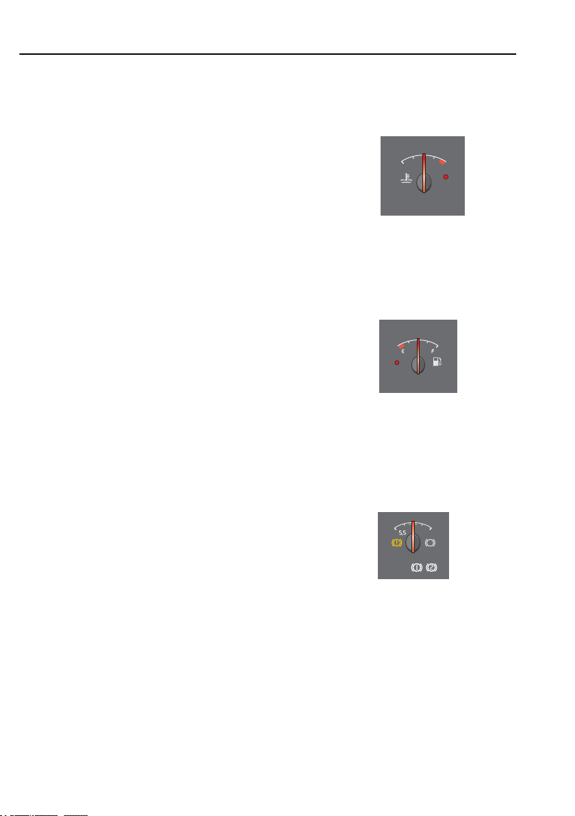
Temperature gauge for coolant
Stop immediately if the warning lamp lights! Let the
engine idle until the warning lamp goes out and the
temperature drops.
Under normal driving conditions, the pointer should
stay below the red zone.
Fuel gauge
When the warning lamp lights, there is 7–10% of the
fuel left in the tank.
J201131
J201134
Air pressure gauge for brakes
Stop immediately if a warning lamp lights! If the lamp
lights while the engine is running, an acoustic alarm
sounds. In addition the STOP lamp lights and a
warning message is shown in the display. The warning
lamp lights if the air pressure in the braking system is
too low. Investigate the cause of the pressure drop.
When the engine is started after it has not run for a
while, the air pressure can have dropped to a level too
low for driving away. The warning lamp will remain
lit until the air pressure has risen to the correct level. If
there is no air in the braking system, it can take some
time before the indicator needle begins to move.
During driving the needle should remain within the
green zone, but when braking it may go below the
green zone for a short time.
J201135
Page 30
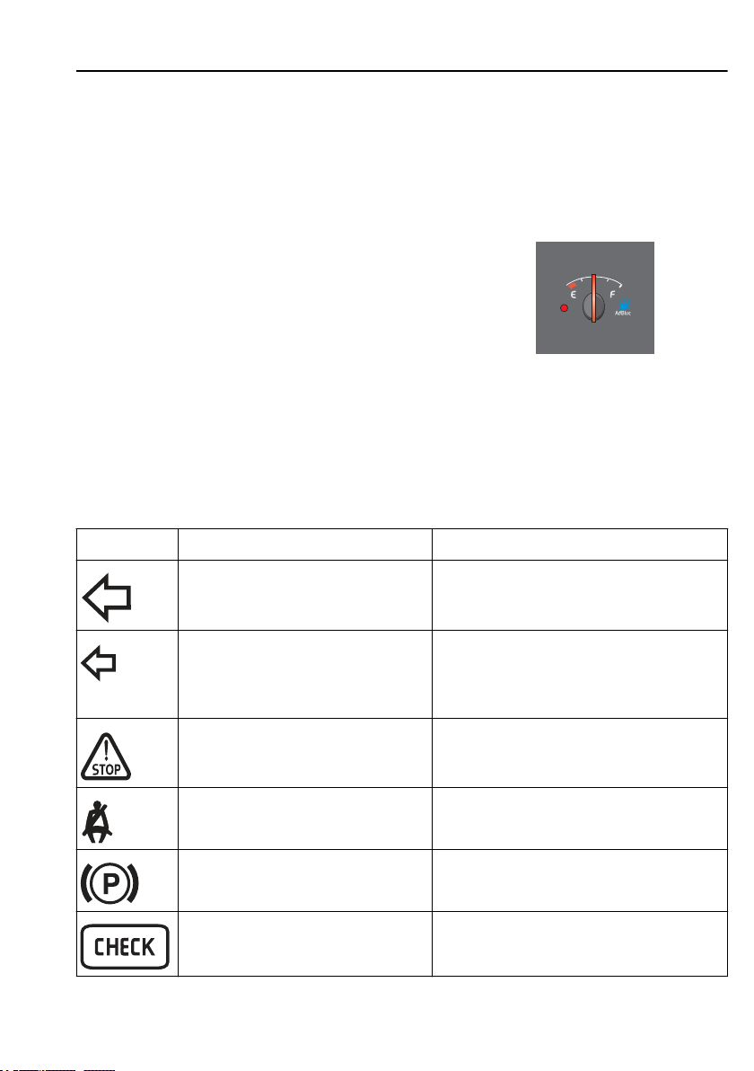
Instruments and controls
When “1” lights, the gauge shows the air pressure in
the front brake circuit and when “2” lights, the air
pressure in the rear brake circuit is shown.
Level gauge for AdBlue
This gauge indicates the approximate amount of
in the tank. The red sector and the yellow
AdBlue
LED indicate when
Symbols
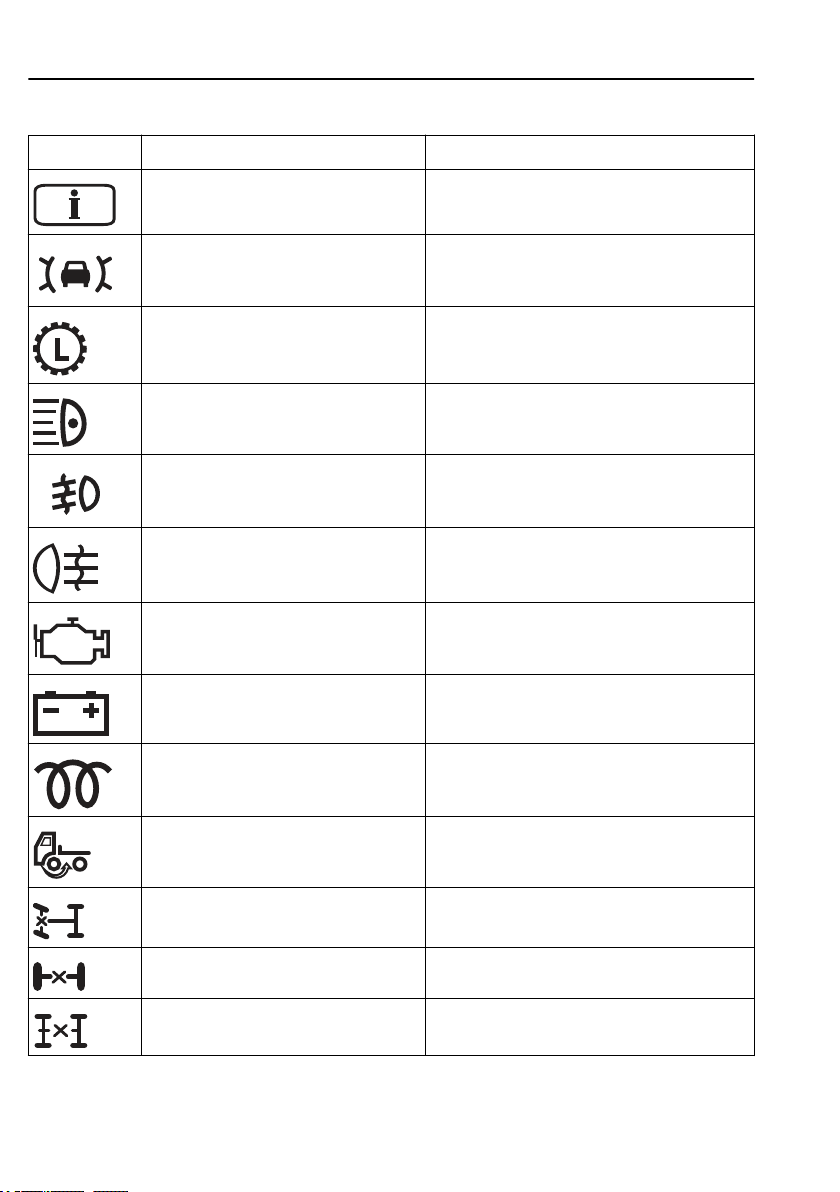
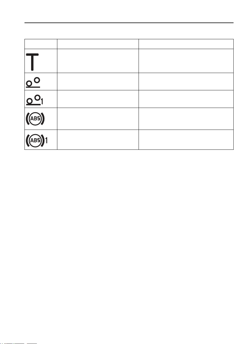
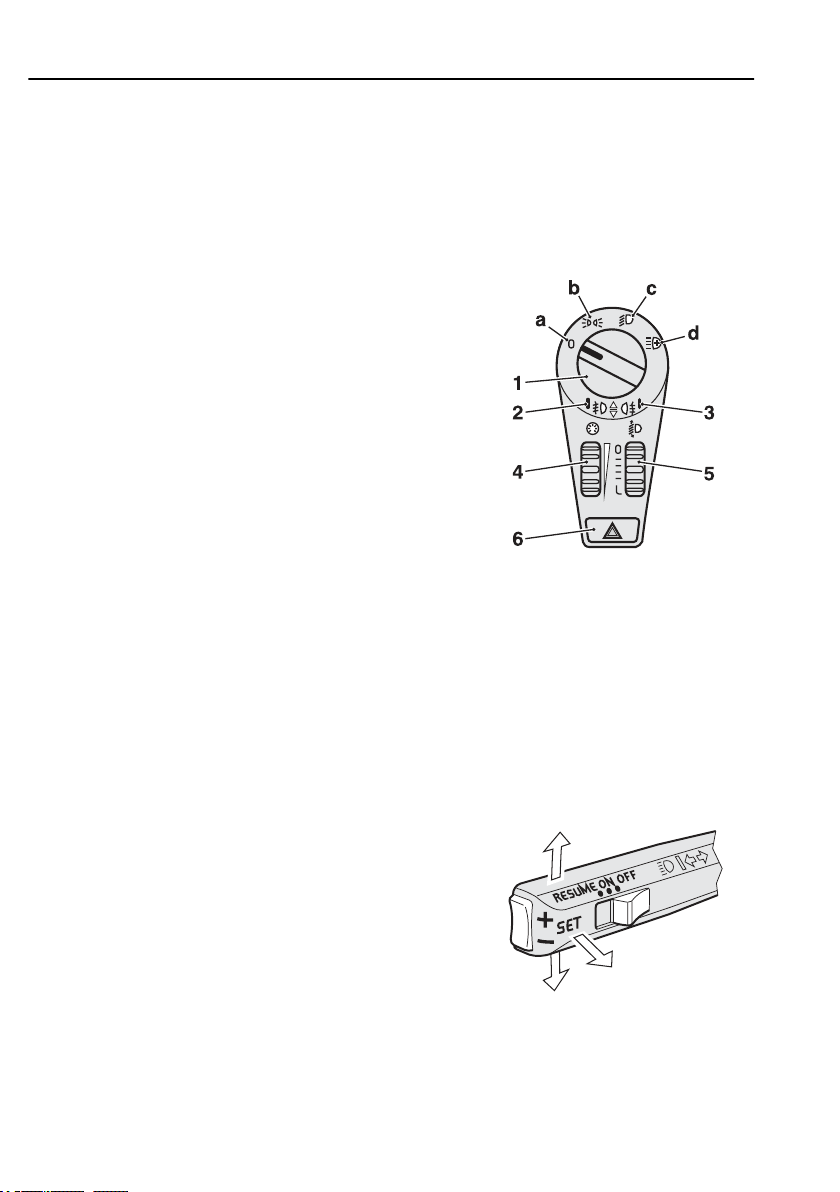
The symbols shown on the driver information display
are described in section describing the display.
Symbol Meaning Note
AdBlue
should be filled.
19
J201136
Left indicator on In the case of a fault the arrow flashes twice as
Left indicator on (trailer) In the case of a fault the arrow flashes twice as
Stop, there is a fault on the truck Lights up together with another symbol
Seat belt reminder
Parking brake applied
Check Lights up together with some other symbol or
fast.
fast.
Note! Fault indication will not occur if LEDs are
used for the trailer lighting.
or with a message on the display.
together with a message on the display.
Page 31
20
Symbol Meaning Note
Instruments and controls
Information Lights up together with some other symbol or
ACC (Adaptive Cruise Control) Green lamp = ACC has detected a vehicle. Red
Low split gear engaged
Main beam on
Front fog lamps on
Rear fog lamps on
Emissions-related fault Contact a workshop; a fault has occurred in the
Battery not charging
Pre-heating on
together with a message on the display.
lamp = collision warning, driver must brake.
engine which can have negative environmental
effects.
Front wheel drive engaged
Differential lock engaged between the
front wheels
Differential lock engaged between wheels Flashes
Differential lock engaged between axles
Page 32
Instruments and controls
Symbol Meaning Note
Check the tachograph Refer to the error menu in the tachograph display.
21
The bogie lift switch is on. On trucks equipped with A-ride, the symbol
The trailer bogie lift switch is on
ABS fault on tractor vehicle If the symbol lights up at speeds exceeding
ABS fault on trailer
indicates the end position.
, the ABS is disengaged. The braking
7 km/h
system operates as if no ABS is available.
Page 33
22
Instruments and controls
Lighting and headlamps
The equipment may vary in different markets.
Headlights
• Parking lights: Turn the lighting switch (1) to b.
• Dip beam: Turn the lighting switch (1) to c.
• Main beam: Turn the lighting switch (1) to c and
pull the main beam stalk towards you.
• Main beam and additional lamps (spotlights):
Turn the lighting switch (1) to d and pull the main
beam stalk towards you.
1 Lighting switch
2 Indicator for front fog lamp
3 Indication (repeater) for rear fog lamp
4 Instrumentation lighting
5 Vertical adjustment of headlamps (extra)
6 Hazard warning flashers
J0010330
Day Running Light
Turn the lighting switch (1) to position a. The dipped
beam and the parking lamps will come on when the
engine is started.
Fog light
The light switch (1) must be positioned in b, c or d for
the fog lamp to come on. In position b, the rear fog
lamps only function if the front fog lamps are lit.
• Front fog lamp: Push the lighting switch in (1).
Indicator lamp (2) lights. Extinguish the fog lamp
by pressing in the lighting switch (1) again.
• Rear fog lamp: Pull out the lighting switch (1).
The indicator lamp (3) and the control lamp light
up. Extinguish the rear fog lamp by pulling out the
lighting switch (1) again.
J3015656
Stalk for main beam and direction
indicators.
Page 34

1
2
Instruments and controls
The fog lamps go out if the lighting switch (1) is set to
position a or if the ignition is turned off. If the lighting
switch (1) is set to another position again or if the
ignition is turned on again, the fog lamps must be
turned on manually again.
Guide lights (PS-LIGHT)
Certain parts of the exterior lighting (main and dipped
beam, parking lights) can be kept lit and function as
guide lights after the truck has been locked. The time
delay can be set between 0 and 254 seconds and is
done at a workshop.
• The key should be in position 0.
• The function is activated by holding the “main
beam and direction indicator” stalk in position 1 for
3 seconds.
• Step out of the truck and lock the door.
Pressing the lock button on the remote control once
more resets the timer so that the selected time starts
again from zero.
The function is inactivated by holding the “main beam
and direction indicator” stalk in position 1 for 3
seconds.
23
J201647
Dipping for left-hand or right-hand traffic
The headlamps are asymmetrical, which means that
trucks for right-hand traffic have the light beam
concentrated to the right and for left-hand traffic to the
left. When a truck for right-hand traffic is driven in a
country with left-hand traffic, the oncoming traffic is
therefore dazzled.
To eliminate this problem:
1 Fold out the headlamp.
2 Remove the cover for the lower lamp.
3 Move the lever on the side of the lamp towards
the truck.
To change back again, move the lever away from the
truck.
Page 35
24
Static cornering light
Static cornering light
left and right.
The light is activated by a switch in the instrument
panel. Light on each respective
side is lit when:
the speed is below 40 km/h
and
the flashers for either direction are on
Identification lamps
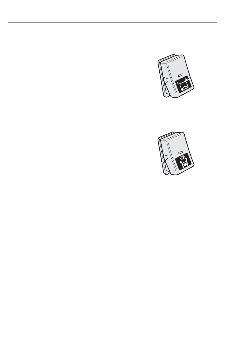
Activate the identification lamps by pressing the
switch. An indicator LED in the switch lights.
Switch off the identification lamps by pressing the
switch again. The LED in the switch goes out.
Instruments and controls
lights up dark areas when turning
J192304
Page 36
Esc
Instruments and controls
Windscreen wipers
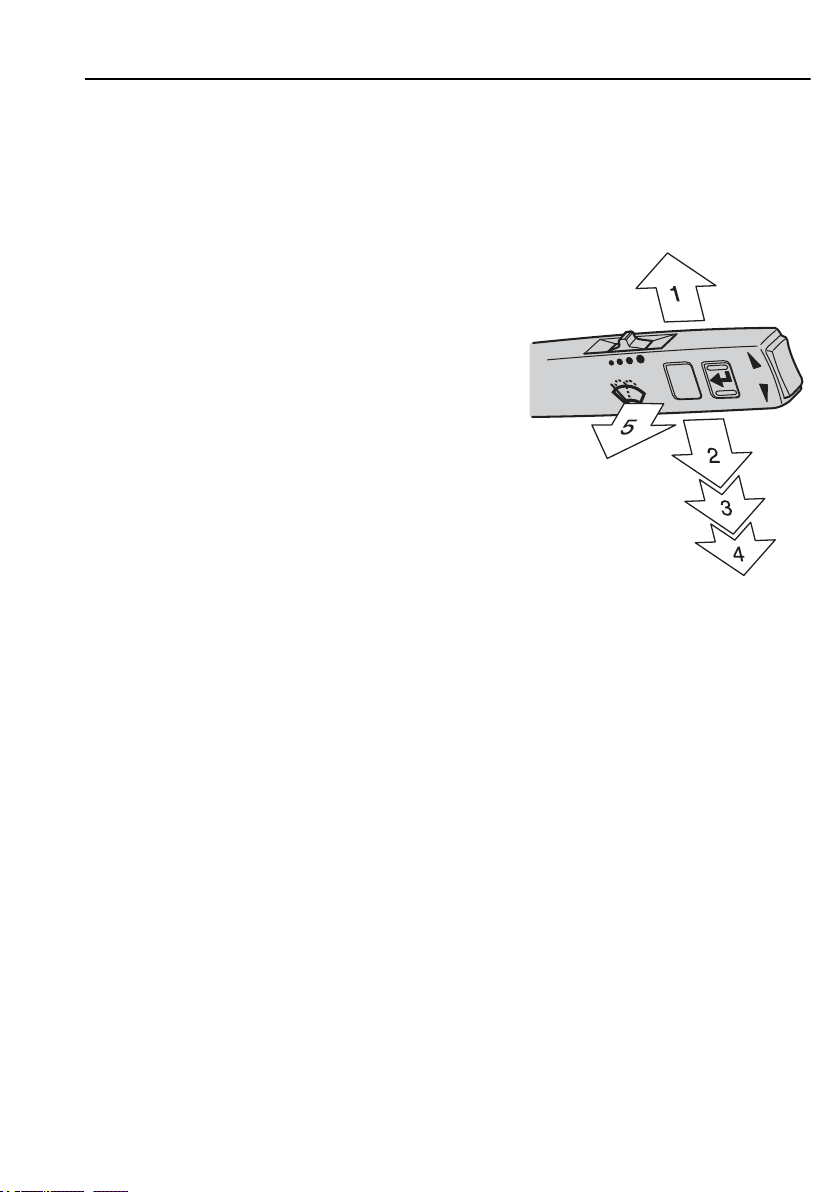
Function
1 Intermittent wiping
2 Spring-return position
3 Windscreen wiper, normal speed
4 Windscreen wiper, high speed
5 Windscreen washers and wipers and headlamp
washer
The time intervals for the intermittent wipers can be
adjusted by the slide control on top of the stalk. The
interval time can be set from 1 to 10 seconds.
25
J166524
Rain sensor
If the truck is fitted with a rain sensor, it senses the
amount of rain against the windscreen and determines
the speed of the windscreen wipers.
The sensitivity of the rain sensor can be adjusted with
a slide control on top of the stalk.
Note!
Note! The sensitivity of the rain
sensor can vary in different weather
conditions.
Page 37
Esc
26
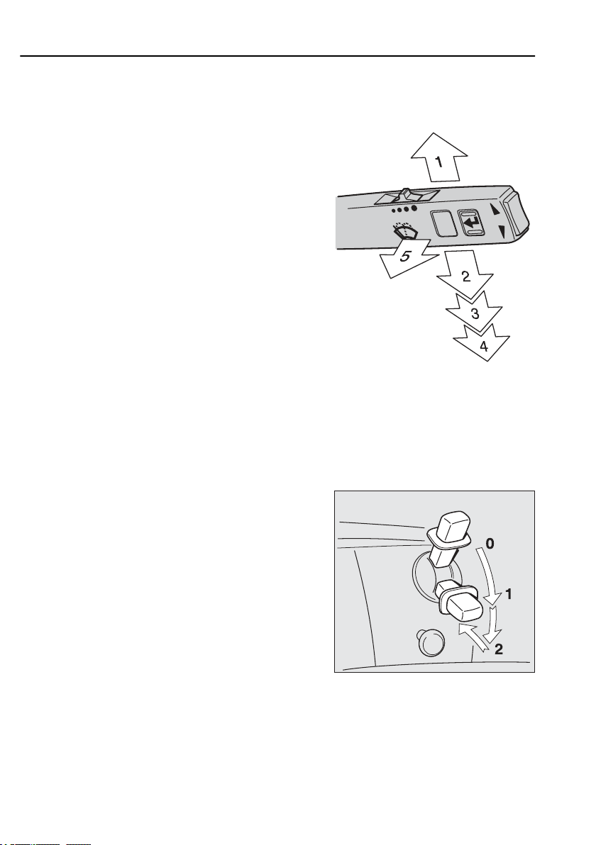
Function
1 Rain sensor on
2 Spring-return position
3 Windscreen wiper, normal speed
4 Windscreen wiper, high speed
5 Windscreen washers and wipers and headlamp
The rain sensor can be switched off by moving the
stalk to the neutral position for two to four seconds
and then up again. The windscreen wiper is then in the
intermittent mode. The interval is controlled by a slide
control on top of the stalk. Repeat the procedure to
reactivate the rain sensor.
Instruments and controls
washer
Parking brake
J166524
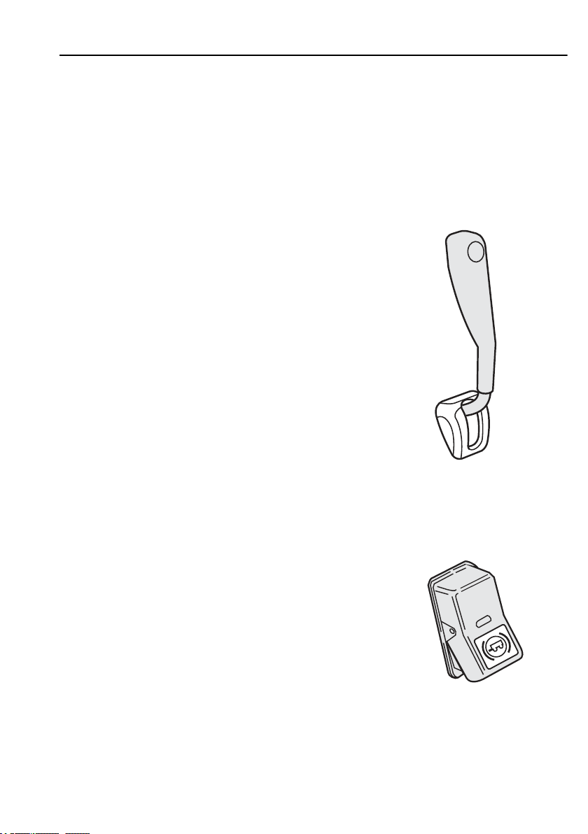
Hand control
0 Parking brake released
0–1 The parking brake for the tractor and trailer are
applied gradually between positions 0 and 1. If a
problem occurs with the service brakes, this position
can be used as an emergency brake.
1 Parking brake applied on tractor unit and service
brakes on trailer.
2 ”Parking position”. Parking brake released on the
tractor unit, no brake on the trailer vehicle. The lever
in locked position.
J5012236
Page 38
Instruments and controls
Blocking valve
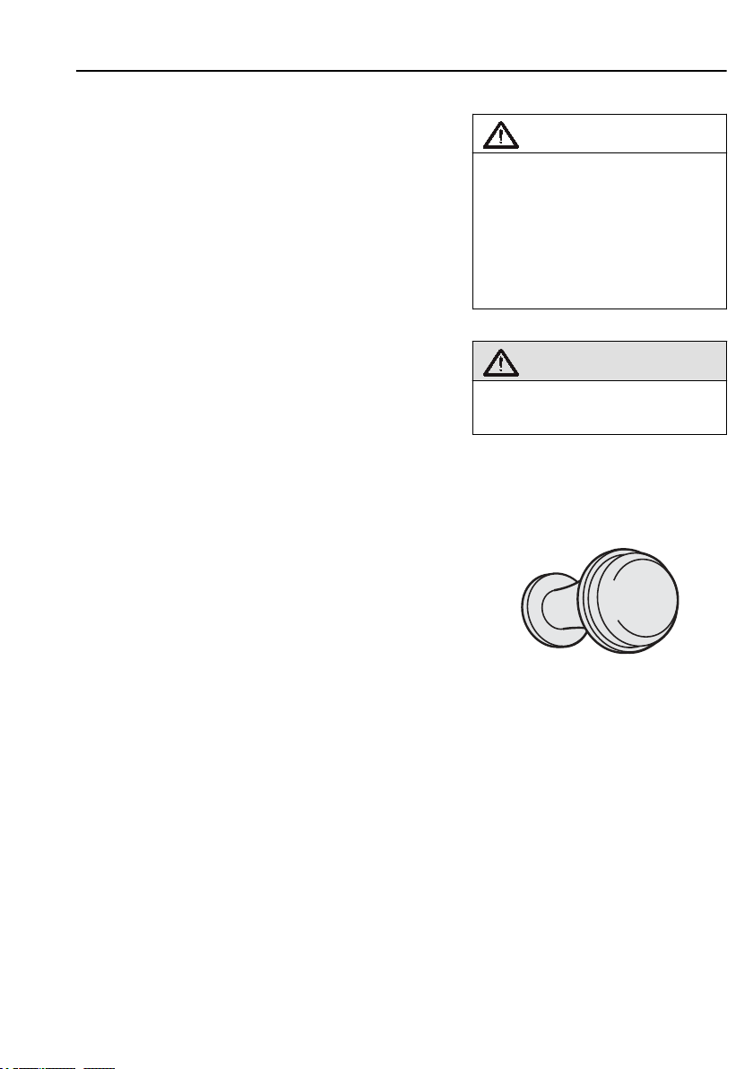
If the pressure in the braking system is too low, for
example if the truck has been parked for a long period
of time, the blocking valve must be pushed in for the
hand-operated parking brake to be released. Before the
blocking valve can be pushed in the pressure in the
braking system must be approximately
5 bar
.
27
Caution!
Always apply the parking brake
when you leave the vehicle. If the
parking brake is not applied, a
symbol on the display will start to
flash, and at the same time an
audible warning will sound to
alert the driver.
Warning!
Check that the lever is in locked
position (position 2).
J0008051
Page 39

28
Instruments and controls
Using the trailer service brake when
parking
To ensure that the braking effect when parking a
vehicle combo does not diminish due to air leakage,
the spring brakes only are applied on the truck when
parking. However, in certain situations, such as
parking on slippery surfaces or on steep slopes with
heavy loads, it can be advantageous to apply the trailer
service brakes as well.
To activate the trailer service brakes for parking, pull
the blocking valve button out until it remains out. The
trailer brakes will now be activated as long as there is
pressure in their brake systems.
Note!
As the pressure will gradually leak
out from the trailer, this method
should only be used temporarily and
with the engine running. If the
vehicle needs to be parked in this
way (without the engine running) the
wheels must be chocked or you must
check that the vehicle remains
parked (does not roll away) even
without the help of the trailer's
brakes.
Page 40
Trailer brake
Instruments and controls
Note!
This control must not be used as a
parking brake.
29
Electric trailer brake
Depress the switch to brake the trailer.
Speed must be less than
engaged. The brake is disengaged if speed exceeds
or when the switch is released.
7 km/h
When the brake is applied, the indication lamp in the
switch lights up.
for the brake to be
4 km/h
J0008056
J0008526
Page 41
30
Instruments and controls
Air suspension
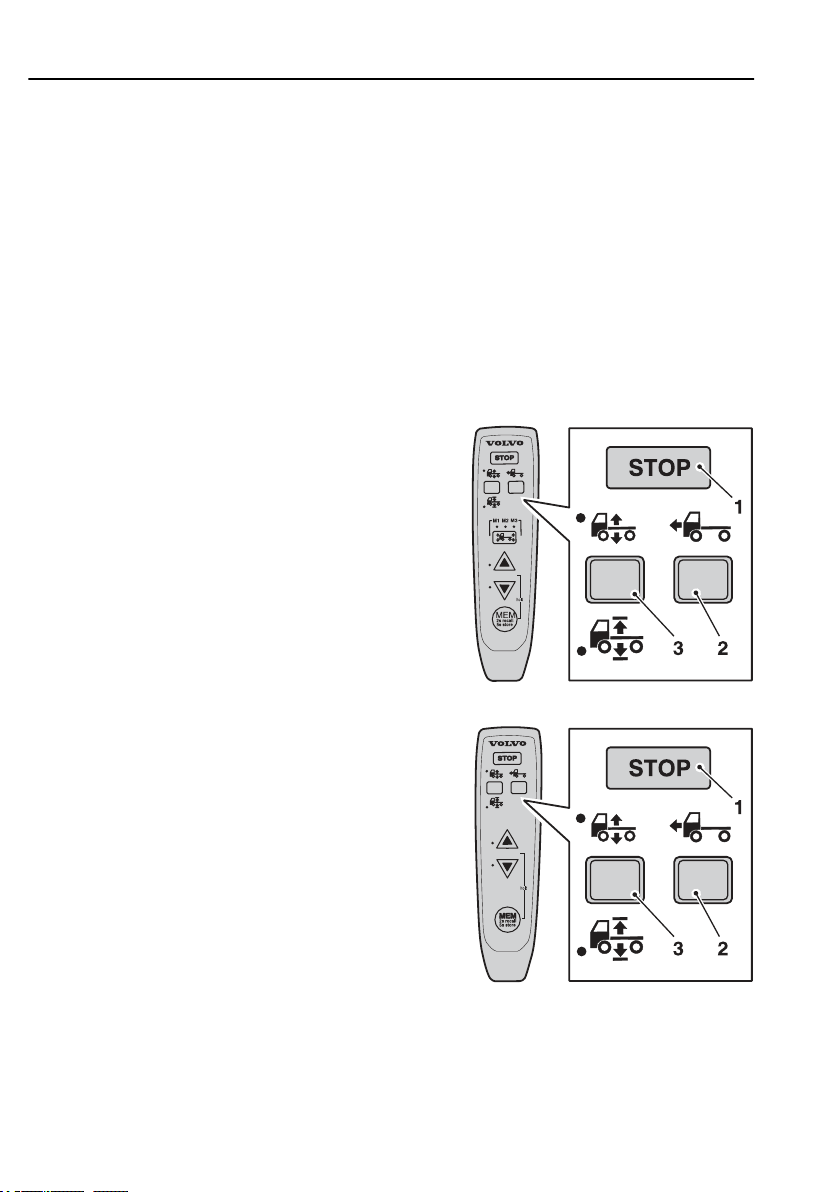
Remote control box
More information about how the air suspension and
control box can be used will be found in chapters
"Driving" and "Loading and unloading".
Road speed must be lower than
control box is used.
Control buttons
To specify air suspension function:
1 STOP, cancels regulation.
2 Drive position, for normal driving.
3 Manual control.
Changing ride height.
30 km/h
when the
J7009817
J7009830
Page 42
Instruments and controls
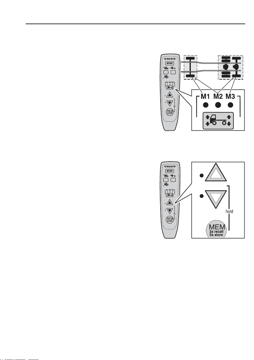
Axle button
To specify which axle is to be adjusted or which
memory is to be used:
• M1, front axle or memory 1.
• M2, front and rear axle or memory 2.
• M3, rear axle or memory 3.
Control buttons
To raise or lower the truck.
To avoid having to hold in the control button, for
example when raising or lowering the truck to it's
highest or lowest height, activate the hold function.
Press one of the control buttons and at the same time
press the memory button. To cancel the hold function,
press the memory button again, one of the control
buttons, or STOP.
31
J7009818
J7009819
Page 43
32
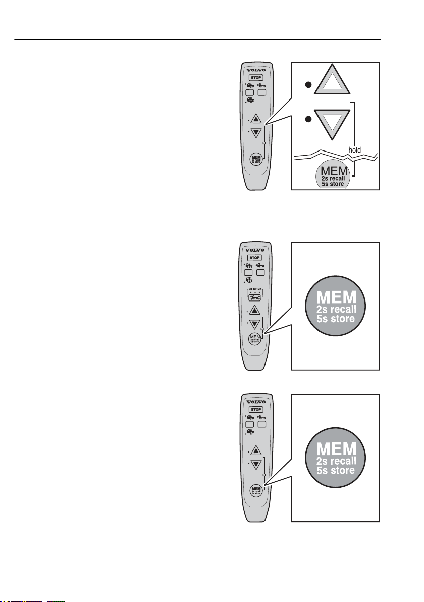
Memory button
To store or retrieve the memory content.
Instruments and controls
J7009831
J7009820
J7009832
Page 44
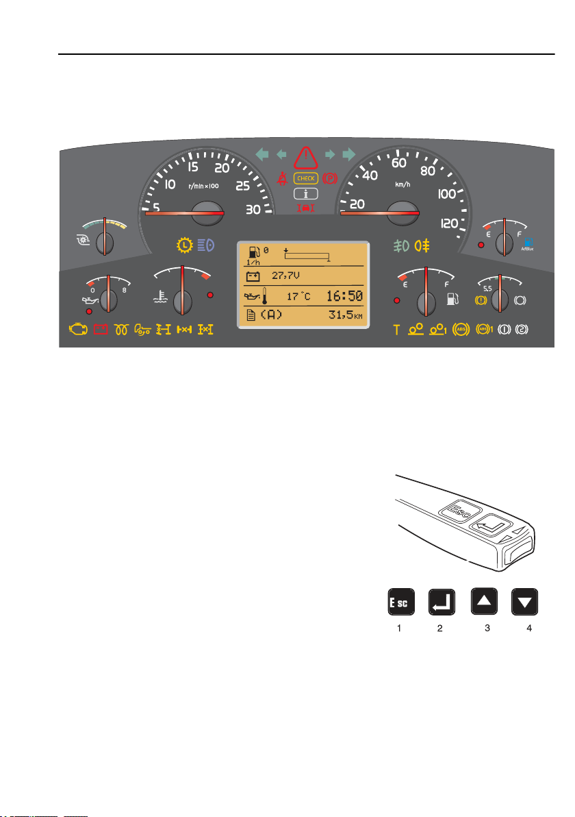
General, about the display
-4A
STOP
The display is located in the middle of the the
instrument cluster. You can use the display to see
vehicle messages, control certain functions on the
truck and see information about the truck, amongst
them temperatures, levels and distances.
The display is controlled via the control unit to the
right of the steering wheel. There are four buttons:
1 Esc
2 "Select"
3 ▲
4 ▼
Information display
33
J201126
Page 45
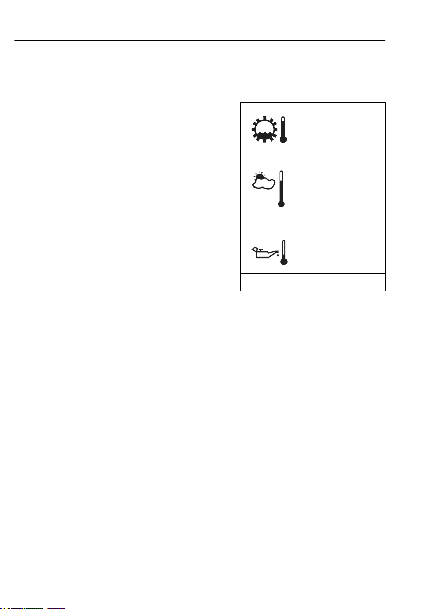
34
Information display
The first that is shown
The display lights up when the key is turned to the
drive position.
If there are no active vehicle messages, the favourite
display is shown. You select what is to be displayed,
see “favourite display, setting”.
The favourite display is shown all the time if there are
no vehicle messages to show or unless you select one
of the menus. To enter the menu system in the display,
press “SELECT” on the control unit. See section
“Menus” for more information about the menus.
If there are vehicle messages, these are shown instead
of the favourite display. The number of the message
shown and the total number are shown in the upper
right corner. 3/3, for example, means that the vehicle
message currently being displayed is the third message
of three active messages. Step between the vehicle
messages using ▲ and ▼. Take suitable actions and
then acknowledge them with “Esc”. For more
information about vehicle messages, see section
“Messages and symbols”.
75ºC
15ºC
98ºC 11:45
AM
CC 7658.8 Km
General, about messages
If there is a fault in the truck or if something happens
that requires attention, such as the outdoor temperature
approaching freezing point, a vehicle message is
displayed or a symbol appears in the display.
If several messages appear at the same time, only the
most important message is displayed. Step between the
vehicle messages using ▲ and ▼.
To obtain more detailed technical information about
vehicle messages, see section “Fault diagnosis”.
Page 46

Information display
Information messages
When this light comes on a new information message
is displayed. The lamp is used for information. The
lamp being lit does not mean that there is a fault in the
vehicle.
Acknowledge the message with “Esc”. If the message
is still valid, it will be shown again the next time the
key is turned to the starting position. Previously
displayed messages can also be seen at “Vehicle
messages”.
If a message appears on the display and is
acknowledged, it can appear on the display again if the
reason for the message disappears after
acknowledgement but then reappears.
Example: If the gearbox oil temperature becomes too
high, a message is activated automatically. The driver
acknowledges this message using “Esc”. If the
temperature then drops to a normal level but then
becomes too high again, the message will be shown
again.
35
J3014366
Warning messages
Acknowledge the message with ”Esc”. If the fault is
still active, it will be shown again next time the starter
key is turned to the starting position. Previously
displayed messages can also be seen at “Vehicle
messages”. If a fault message appears on the display
and is acknowledged, it can appear on the display
again if the fault disappears after acknowledgement
but then reappears again.
Note!
This lamp lights when something
must be rectified. If it is a fault on
the truck, the truck shall be driven to
a workshop for repair. The truck will
not be damaged immediately and can
in certain circumstances complete
it's assignment first. It may also be
something that the driver can correct
himself, such as high temperature in
the transmission, by driving more
sedately or stopping the truck for a
while.
Page 47
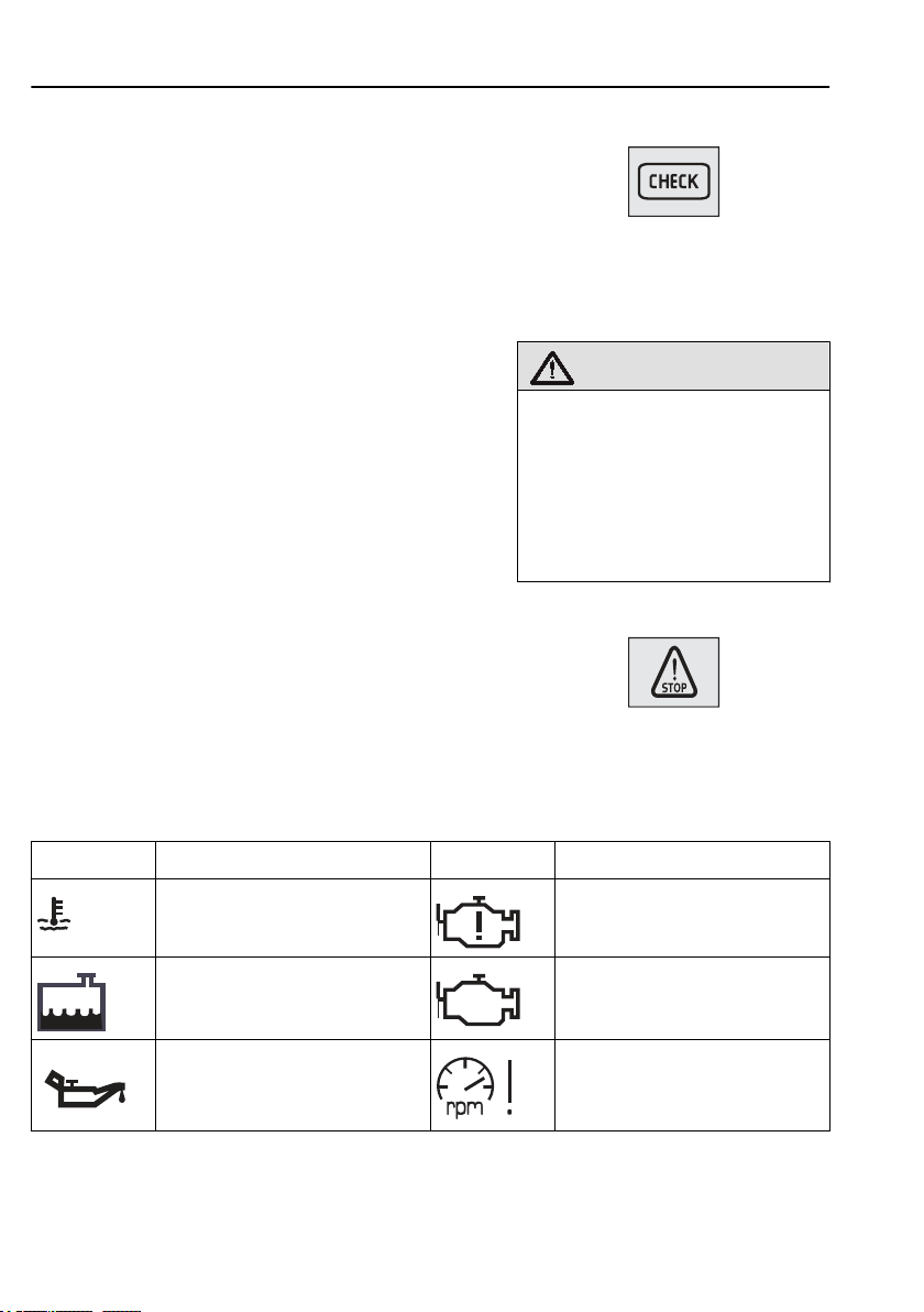
36
Information display
Stop message
A buzzer sounds at the same time as a stop message is
displayed. The buzzer and stop message can be
acknowledged with "ESC", but will be repeated after
10 seconds. The symbol is lit continuously.
J3014365
Warning!
When this lamp lights, the vehicle
must be stopped immediately and
the engine switched off. If the
vehicle is not stopped and the
engine turned off, there will be
serious consequences for the
vehicle, driver or load.
Alarm, warning and information symbols
Symbol Meaning Symbol Meaning
High temperature, coolant Crankcase pressure too high
Low level, engine coolant Engine fault
Low oil pressure, engine oil Engine speed too high
J3014364
Page 48
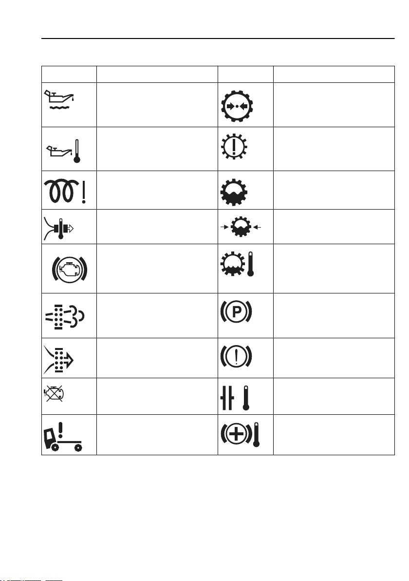
Information display
Symbol Meaning Symbol Meaning
Low oil level, engine oil Low air pressure, gearbox
37
High temperature,
engine oil
Pre-heating fault Low level, gearbox oil
High temperature,
inlet manifold
Engine temperature too
low for engine brake
(VEB)
Too high concentration of soot
particles or ash in the particulate
filter. See section “Particulate filter”
for more information.
Air filter clogged. Check that the net
in the air intake is not clogged.
Engine is switched off Clutch running hot
Gearbox fault
Low oil pressure, gearbox
High temperature,
gearbox oil
Parking brake applied
Brake pressure low
Cab tilt lock open Temperature, hydraulic
retarder
Page 49
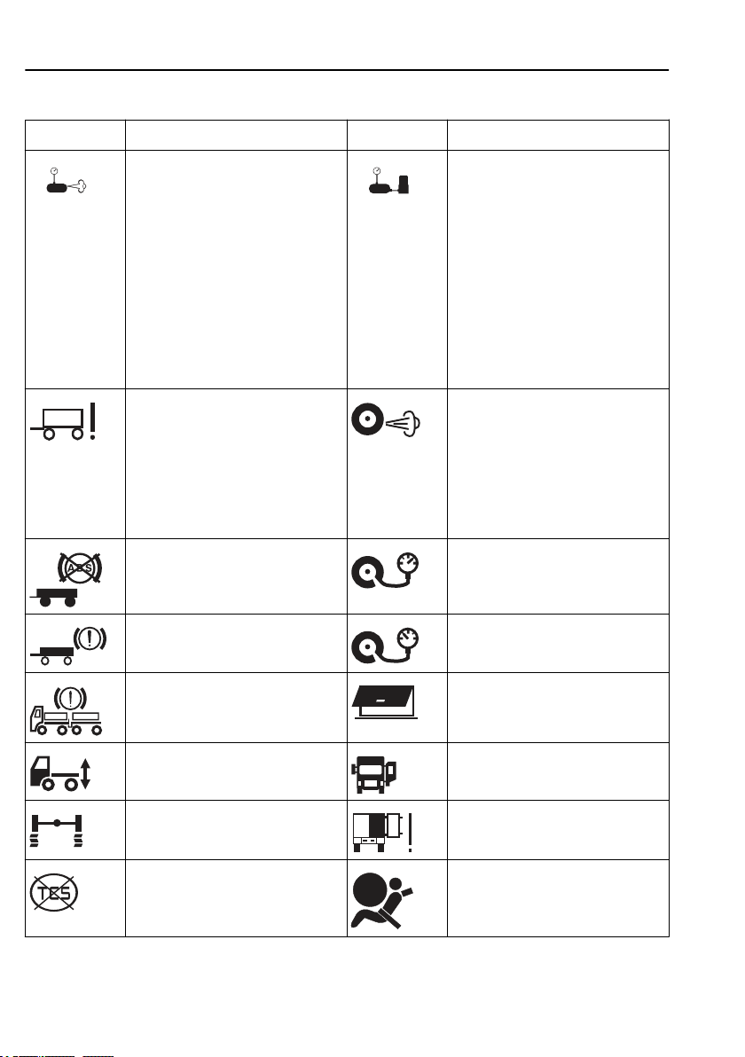
38
Symbol Meaning Symbol Meaning
Information display
The compressor charge is unusually
high. The cause could be air leakage.
• If the symbol is shown together
with the information symbol (i),
the leakage is so large that fuel
consumption
is increased.
• If the symbol is displayed
together with the check symbol
(CHECK), then the leakage is so
large that it can cause an
unplanned stop if not remedied.
Fault in trailer EBS function Leakage from indicated tyre/axle.
Connected trailer without ABS High tyre pressure
Poor brake effect on
trailer
Risk of moisture in the pneumatic
system. There are several causes:
• Time to replace the desiccant
element.
• The compressor is being used to
much.
• Fault with the air system.
This warning may also occur after
changing tyres. Disable by
unscrewing the hose to the tyre
pressure sensor on the tyre in
question, wait for a minute and then
screw on again. (Key in drive
position)
Low tyre pressure
Uneven braking effect between
tractor and trailer
Low pressure in the air suspension
system
Wheel spin or ABS activated Door to cargo hold
Traction Control Function
temporarily disengaged
Baggage door open
Door open
open
Airbag
Page 50
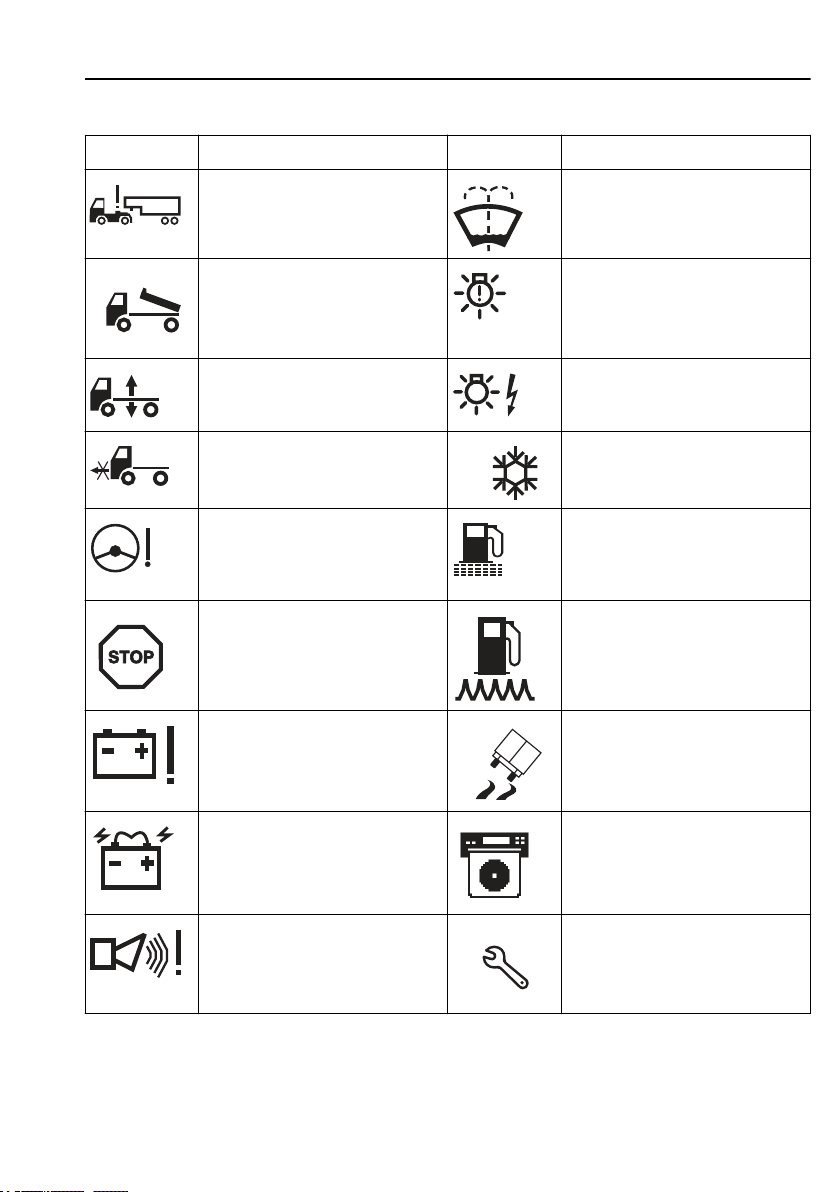
Information display
Symbol Meaning Symbol Meaning
Trailer disconnected Low level washer fluid
Superstructure not in drive position One or more lamps do not light.
39
Air suspension in manual position Fault in the electrical system causing
Air suspension not in drive position Warning freezing conditions
Low pressure or flow in steering
servo. The symbol might be
displayed when stationary or at low
speeds without there being a fault.
Stop Low fuel level
Voltage warning Stability control active
Battery discharge Diagram sheet box open or sheet for
Alarm in service mode. Service reminder
lamp not to light. Can cause a
hardware fault in the electronics.
Fuel filter clogged
driver 1 missing. (Only for certain
variants)
Page 51
40
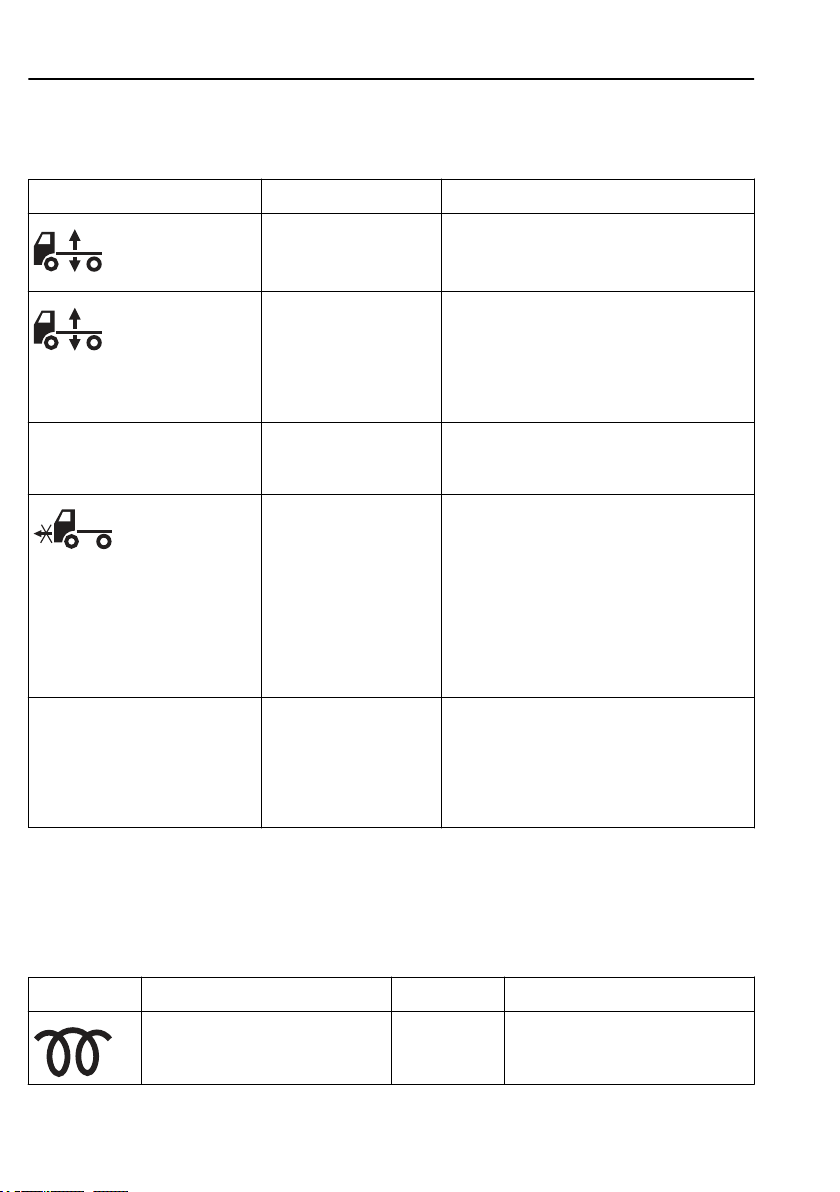
Information display
Symbols for air suspension
Symbol Meaning Action
The control button is set
to manual control or
adjustment of ride height.
If the control button is in
the centre position the air
suspension is in locked
position.
Axle load distribution 70% With "optimise traction",
CHECK THE AIR SUSPENSION
AT THE NEXT STOP
the axle load distribution
is shown in the display.
Truck not in drive
position.
There is an air suspension
malfunction.
Select ride height
Note! Drive very carefully when the symbol is
displayed.
Check whether the air suspension is locked:
Turn the ignition key to the stop position (0)
and then back to the drive position (I).
If the symbol remains on the display the air
suspension is locked. See section "Air
suspension in locked position", page 628.
None. The message disappears when optimal
load distribution has been achieved.
Check that the control button is in the drive
position and wait until the truck reaches the
correct drive height.
Note! Drive very carefully when the symbol is
displayed.
A signal will sound if the speed is too high. If
a bellows is punctured, drive, at not more than
, to a Volvo workshop, or contact
30 km/h
Volvo Action Service.
Check whether the fault is active at the next
stop: Turn the ignition key to the stop position
(0) and then back to the drive position (I). If
the message remains in the display, the fault is
active. See section "Air suspension in locked
position".
Status symbols
Status symbols are shown in the lowest row of the
display.
Symbol Meaning Symbol Meaning
Air intake heating or air intake
heating fault
LCS
Lane Change Support
active
Page 52
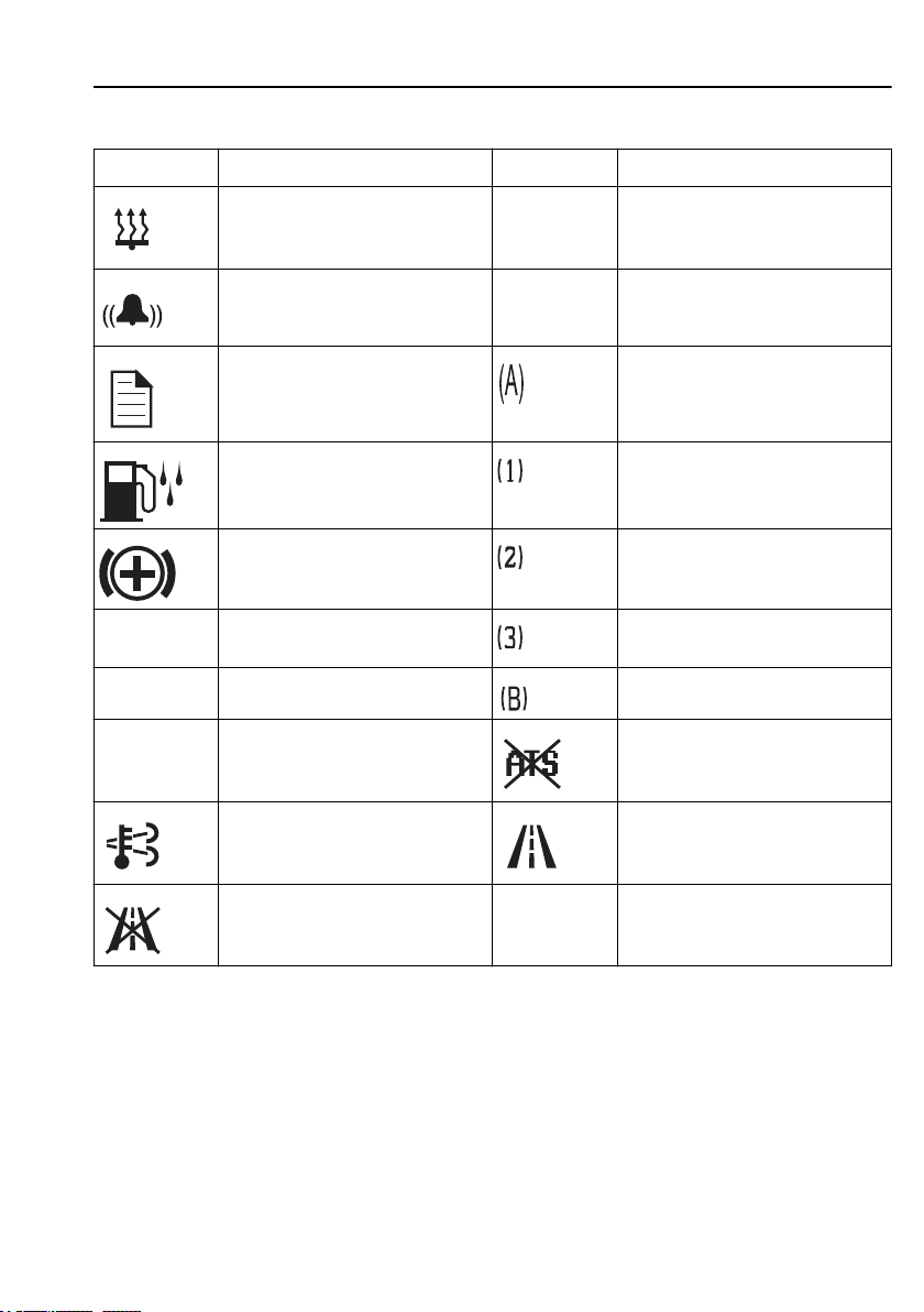
Information display
Symbol Meaning Symbol Meaning
Parking heater timer activated CC Cruise control active
Alarm clock activated ACC Adaptive cruise control active
Message active Auxiliary brake position A
41
Water in fuel
(draining required)
Auxiliary brake working Auxiliary brake position 2
MI Odometer, miles Auxiliary brake position 3
KM Odometer, kilometres Auxiliary brake position B
PTO Power take-off active ATS (Aftertreatment system)
High temperature, exhaust system
Lane Keeping Support
inactive
(LKS)
Auxiliary brake position 1
inactive
Lane Keeping Support
Other Symbols
There are even more symbols within different menus
that have not been included here. See the description
of the menu in question for an explanation.
(LKS) active
Page 53

42
Information display
Menu structure
Menus when driving
1 Gauges
1.1 Temperature, outside
1.2 Temperature, engine oil
1.3 Temperature, gearbox
1.4 Voltmeter/Ammeter
1.5 Gear position
1.6 Pressure, primary tank
2 Fuel data
2.1 Fuel consumption
2.2 Stage data
2.3 Remaining fuel
2.4 AdBlue
3 Time/distance
3.1 Tripmeter
3.2 Average speed
3.3 Estimated arrival time
3.4 Clock and Date
3.5 Alarm clock
3.6 Driving/rest time
4 Display
4.1 Black panel
4.2 Backlight
4.3 Favourite display, setting
4.4 Night/Day
5 Vehicle messages
6 Tyre pressure
7 Reset
7.1 Reset
Page 54

Information display
8 ATS¹
8.1 Start regeneration
8.2 Activate/Deactivate ATS
8.3 System conditions
8.4 Soot/ash level
¹ Only on trucks with variants JPN07 and EAS-DPF
Menus when stationary
1 P-heater timer
1.1 Programming
1.2 Reset
2 Display setting
2.1 Language
2.2 Units
2.3 Time/Date
2.4 Display light
2.5 Change password¹
43
3 Vehicle Settings
3.1 Traction control
3.2 DAS
3.3 LCD
3.4 Fleet Limits¹
3.5 Current sensor calibration
3.6 Fleet ID¹
3.7 Day running lights automatic
3.8 Draining/priming
3.9 Set wheel ID
3.10 Set reference pressure
4 Diagnostics
4.1 Fault diagnostics
4.2 Cluster selftest
4.3 Part number
Page 55

44
5 Vehicle data
6 Maintenance
1
Password protected menu.
Information display
5.1 Oil level
5.2 Load indicator
5.3 Brake linings, status
6.1 Service Warning
Page 56
Information display
Show menus
If no other message is shown, the favourite display
will be shown. To enter the menu system, press
"SELECT" on the control unit.
For reasons of safety, not all menus are available when
driving. To see certain menus and to make certain
settings, the truck must be stationary.
75 °C
15 °C
98 °C
45
11:45
AM
7658.8
km
Step between the menus
1 Move the cursor between menus using ▲ and ▼.
The order number of the marked menu is shown
in the top right corner. 2/6 indicates that there are
6 menus and that the current menu is number 2.
2 Go from a menu to a sub-menu using "SELECT".
3 Leave a sub-menu with "Esc".
Change a setting
Example:
The display shows the favourite display and you wish
to set the alarm clock to ring at 05:45.
1 Go to the menus using "SELECT".
Put the cursor on "Time/Distance" with ▲and ▼.
Page 57

46
2 Press "SELECT".
3 Step the alarm clock with ▲ and ▼.
4 Press "SELECT".
5 Press "SELECT".
6
7
8
9
10
Information display
The current time and date are shown.
Step down to ”NEW TIME” with ▲ and ▼.
The hours are marked.
Step to the required hour using ▲ and ▼.
Press "SELECT".
The first digit for minutes is marked.
Step to the required digit using ▲ and ▼.
Press "SELECT".
The second digit for minutes is marked.
Step to the required digit using ▲ and ▼.
Press "SELECT".
”ON” is marked.
Press "SELECT".
A cross is place in the box in front of "ON" and
the symbol for activated alarm clock is shown in
the status bar. The alarm clock setting is then
automatically displayed.
Go back to favourite display with "Esc". The
symbol for activated alarm clock is shown in the
status bar.
To deactivate the alarm clock:
• Enter the ”Time/Distance” menu
with ”SELECT”.
• Step the alarm clock with ▲ and ▼.
• Press "SELECT".
• Step to ”OFF” with ▲ and ▼.
• Press "SELECT".
Page 58
Temperature, outside
The temperature outside the cab.
Temperature, engine oil
Temperature of the engine oil.
Temperature, gearbox
Temperature of the gearbox oil.
Information display
47
J3005101
J3013611
Voltmeter/Ammeter
Voltage values less than
if the engine speed is less than
minutes. The voltage values higher than
presented as HIGH.
If the ammeter's value becomes too low, the ammeter's
value is shown automatically as well as the text
“Discharge”.
are presented as LOW
20.0 V
800 rpm
for 10
30.0 V
are
J3005098
Note!
Temperatures below 45°C are not
shown.
J3008832
Page 59
48
Information display
Gear position
The menu "Gear position" shows information about
engaged gear, lever position, available gears etc.
For further information about "Gearbox", see separate
driver instructions "
I-shift
" and "
Powertronic
”.
Pressure, primary tank
If the pressure in the primary tank drops below 8 Bar,
a fault message is displayed together with the info/
warning symbol.
Air-suspended vehicles work with two pressure levels:
• Maximum system pressure at standstill (and low
speed)
• Reduced system pressure when driving (reduce fuel
consumption and wear on air compressor)
Certain variants do not have reduced system pressure.
J3016142
Fuel consumption
For setting the units, see section “Units”.
Average fuel consumption:
The value is presented as a figure and an arrow
pointing down, (e.g. ø26.) During a time after resetting
the display shows ”— — — ” while average fuel
consumption is calculated.
Instantaneous fuel consumption:
The value is presented numerically as well as in the
form of a bar.
Target fuel consumption:
The value is displayed as a T upside down below the
bar. For information on setting this value, see section
“Fuel (target)”.
Reset fuel consumption
Press “SELECT”.
J3014498
Note!
At idle, no bar is shown and the fuel
consumption is displayed in litre/hr
(alternatively gallons/hr).
Page 60
Information display
To reset all fuel data, hold “SELECT” pressed in for 1
second.
Stage data is also reset.
Leg data
The amount of fuel consumed since the last reset.
Resetting, stage data
Press “SELECT”.
To reset all stage data, hold “SELECT” pressed in for
1 second.
Fuel consumption (see above) is also reset.
Remaining fuel
• How far one can drive at the current average
consumption
• How much fuel is left in the tank
49
J3013617
J3014498
AdBlue
How much
AdBlue
J0010376
is left in the tank.
J0013296
Page 61
50
Information display
Trip meter
Two independent distances can be saved, for leg 1 and
leg 2.
Reset trip meter
1 Press "SELECT".
2 Mark with ▲ and ▼ if leg 1 or leg 2 is to be
reset.
3 Confirm selection with "SELECT" or depress
"Esc" to exit reset.
J0009587
Note!
The trip values must be reset before
each measurement.
Average speed
The average speed is calculated as the distance driven
divided by the time the engine has been running (since
latest reset). Two different average speeds can be
measured, average speeds 1 and 2.
Reset average speeds
1 Press "SELECT".
2 Mark with ▲ and ▼ if average speed 1 or 2 is to
be reset.
J3013620
Note!
The values must be reset before each
measurement.
Page 62
Information display
3 Confirm selection with "SELECT" or depress
"Esc" to exit reset.
Estimated time of arrival
The estimated time of arrival is calculated as the
remaining distance divided by the vehicle's average
speed.
Show distance
1 Press "SELECT".
2 Enter the remaining distance in km (or miles)
• Set the first digit with ▲ and ▼
• Step to the next digit using "SELECT"
• Step backwards with "Esc"
51
J3013621
Time and Date
The menus "Time and date" and "Alarm Clock" are
available even when the starter key is in the stop
position. The menu is activated by pressing any of the
buttons on the control unit for at least 1 second. The
menu remains active for 30 seconds after the last
depression.
Current time and date. For alternative settings 12h or
24h and date format, see section “Time/date”.
The clock cannot be altered if the truck is equipped
with a tachograph. This is then done in the tachograph
time setting menu instead (see "Operating instructions
Tachograph").
1 Press "SELECT".
2 Set Time and Date
• Set the first digit with ▲ and ▼
• Step to the next digit using "SELECT"
J3013618
Page 63

52
• Step backwards with "Esc"
If the starter key is in stop position and it takes more
than 30 seconds between button depressions, the
setting is aborted.
Information display
Alarm clock
The menu "Alarm Clock" is available even when the
starter key is in stop position. The menu is activated by
pressing any of the buttons on the control unit for at
least 1 second. The menu remains active for 30
seconds after the last depression.
The alarm clock cannot be set when driving, but the
buzzer that sounds when triggered can be shut off by
pressing "Esc".
Alarm clock, setting
1 Press "SELECT".
2 Move the cursor to NEW TIME using ▲ and ▼.
3 Confirm with "SELECT".
4 Enter the alarm time
Set the first digit with ▲ and ▼
Step to the next digit using "SELECT"
Step backwards with ”Esc”
5 ”ON” is then marked. Confirm with "SELECT".
The symbol to the right is shown on the status bar
to indicate that the alarm clock is active.
J3013619
If the starter key is in stop position and it takes more
than 30 seconds between button depressions, the
setting is aborted.
Activate alarm clock
Activating the alarm clock without changing alarm
time:
1 Press "SELECT".
2 Move the cursor to "ON" using ▲ and ▼.
3 Confirm with "SELECT".
Page 64

Information display
4 The symbol for activated alarm clock is shown
on the status bar in the display.
Switch off the alarm clock
When the alarm clock goes off, the word ALARM
lights up, the current time is displayed and a warning
signal is sounded. The alarm shuts off after 60 seconds
or if "ESC" is depressed.
Driving/rest time
Information about driving and rest times are taken
from the digital tachograph (the function is an option).
The symbol is at the far left and the information under
it varies depending on the selected activity in the
digital tachograph. The symbol in the centre indicates
pause and rest time. The symbol to the right indicates
driving time
Black Panel
When "Black Panel" is active, only the speedometer
and tachometer are illuminated (except the coloured
field).
The following events light the backlighting:
• a message is activated
• a button is depressed
• the engine speed enters the red zone on the
tachometer
53
00:25 10:27 2:47
Backlight
The display lighting follows the rheostat setting
(which also controls the other instrument lighting).
This menu can be used to alter the display lighting
with respect to the lighting of the other instruments.
Page 65
54
Information display
Set backlight
1 Increase or decrease the backlighting with ▲ and
▼.
2 Confirm with "SELECT".
3 "Esc" aborts the setting.
Favourite Display, setting
Select which of 13 different gauges and functions to be
shown in “Favourite display”.
No display
Outside temperature
Temperature, engine oil
J0009588
Temperature, gearbox oil
Voltmeter/Ammeter
Gear position
Remaining AdBlue
Fuel consumption
Remaining fuel
Page 66
Stage data
Trip meter
Average road speed
Estimated arrival time
Time/Date
Alarm
Tacho info
Compass
DAS
Information display
55
1 Press “SELECT”.
2 Press “SELECT” once more and the upper field
becomes active. Select the gauge or function
using ▲ and ▼. Acknowledge with “SELECT”
when required
gauge or function is shown.
3 Press “SELECT” once more to activate the next
field. Select the gauge or function using ▲ and
▼. Acknowledge with “SELECT” when the
required gauge or function is shown.
4 Press “SELECT” or “Esc” until all the fields are
active and the clock is shown.
Page 67
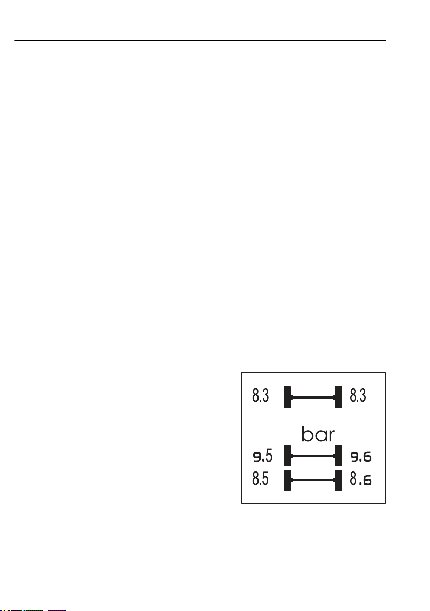
56
Information display
Night/Day
This function is used to activate daylight mode (white
text on a black background) and night mode (black
text on a white background). When the daylight mode
is active, the display changes to night mode if the
lighting is turned on.
Vehicle Messages
If a message is displayed and acknowledged, a symbol
is shown in the status bar. Go into this menu to see
which messages have been acknowledged without
being rectified.
Switch between messages using ▲ and ▼.
Press "ESC" to return to the main menu.
An acknowledged message that is still active the next
time the starter key is turned to drive position will be
displayed as an unacknowledged message. The
message symbol will stay on as long as there are
unacknowledged messages present.
Tyre pressure
This function checks the tire pressures on the truck and
the trailer (if applicable) if the option TPM (Tyre
Pressure Monitoring) is installed.
Switch between measurement points using ▲ and ▼.
J0011924
Page 68

Set wheel ID
1 Select axle with ▲ and ▼
2 Confirm selected axle with "SELECT".
3 Select wheel with ▲ and ▼
4 Confirm selected wheel with "SELECT".
5 Current ID is shown.
6 Adjust ”Newt ID”.
Adjust the marked digit with ▲ and ▼
Confirm each selected digit with "SELECT".
7 Confirm change of ID with "SELECT".
Information display
Note!
The data in the display can vary
depending on how many axles and
tyre pressure sensors are fitted to the
truck.
Note!
It is only possible to read off the tyre
pressure when the truck is stationary.
57
Press "Esc" to return to previous digit, row or menu.
Set reference pressure
1 Select axle with ▲ and ▼
2 Confirm selected axle with "SELECT".
3 Current value is shown
4 Adjust "New value".
Adjust the marked digit with ▲ and ▼
Confirm each selected digit with "SELECT"
5 Confirm reference pressure with "SELECT"
Press "Esc" to return to previous digit, row or menu.
Page 69
58
Information display
Reset
If "SELECT" is depressed for more than 1 second, the
following functions are reset:
• Fuel consumption
• Leg data
• Tripmeters 1 & 2
• Average speeds 1 & 2
ATS
(Only JPN07 and EAS-DPF)
The truck has an exhaust after-treatment system (ATS)
that includes a diesel particulate filter (DPF). When a
certain quantity of soot and ash particles have been
collected, regeneration of the filter is necessary. See
also section ”Diesel particulate filter”.
Caution!
The silencer becomes extremely
hot during regeneration.
Therefore avoid driving or
stopping the truck in unsuitable
places,
for example
fields or close to inflammable
materials or gases.
. in tunnels, in
Start regeneration
This function is used when regeneration must be
started manually.
When regeneration starts, a symbol is shown to the
right and the message ”Regeneration in progress” is
shown in the display.
When regeneration starts the symbol High
temperature, exhaust system is shown in the display.
J3018100
Page 70

Information display
59
If manual regeneration fails, the
message ”Regeneration failed . Check system
conditions.” is shown in the display. To find out why
the regeneration failed, select ”System conditions”(see
below) and check the system conditions.
Abort regeneration
Regeneration can be aborted at any time by:
• turning off the ignition, or
• deactivating ATS (see below)
Activate/Deactivate ATS
To activate/deactivate ATS:
1 Choose ”Activate/deactivate regeneration” with
▲ and ▼.
2 Confirm with "SELECT"
3 Abort with ”Esc”
When ATS is deactivated, the following symbol is
shown on the display. Reactivated ATS as soon as
possible.
Note!
If regeneration is performed while
the engine is idling, the idle speed
may rise.
System conditions
This function shows the status of the system
conditions that must be fulfilled for regeneration to
start (applies only to manual start of regeneration).
The system conditions can have the status OK,
CHECK or N/A. For regeneration to function, all
conditions must have status OK. If any of the
conditions has status CHECK, then regeneration
cannot be performed. N/A means that the condition
does not apply to this truck. See all the system
conditions below.
J129144
Page 71
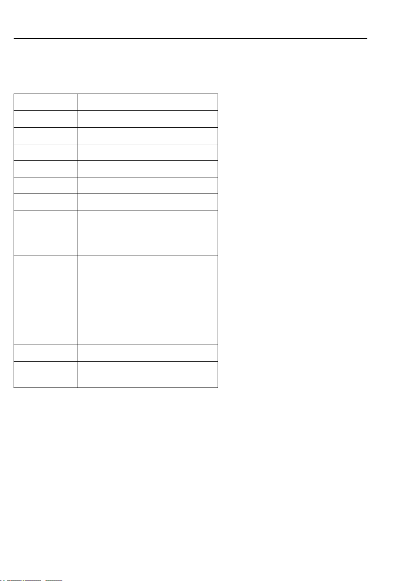
60
Information display
The following table shows the system conditions and
the requirements for them to be fulfilled.
System conditions Status OK if:
Clutch Clutch not depressed
PTO PTO not activated
Accelerator pedal Accelerator pedal not depressed
Gears Gearbox in neutral
Vehicle speed Truck stationary
Handbrake Handbrake applied
System fault Component fault, engine, or diesel
Temporary system
lockout
Permanent system
lockout
Engine Engine running and warmed up
Inactivation
switch
particulate filter do not prevent
regeneration
Action: Contact a Volvo workshop
Soot level is not sufficiently high to start
regeneration
Action: Continue driving as normal until
the soot level requires regeneration
The soot level is too high to permit
regeneration
Action: Stop the truck immediately and
contact your nearest Volvo workshop
“Inactivate ATS” selected by driver
Soot/ash level
The function shows the amount of soot and ash
collected in the filter graphically
Choose which image to show with ”▲ and ▼”.
Programming, p-heater timer
If the timer already has a time set, it will be shown.
1 Press "SELECT".
Page 72

Information display
2 Move the cursor to "Programming" using ▲ and
▼.
3 Confirm with "SELECT".
4 Set the start date with ▲ and ▼
Current date is default.
5 Confirm with "SELECT".
6 Set the start time with ▲ and ▼
7 Confirm with "SELECT".
8 Set duration with ▲ and ▼
The time is changed in 10 minute intervals. The
longest time that can be set is 2 hours.
9 Confirm with "SELECT".
10 The set time and date are shown.
11 Confirm with "SELECT".
Reset, p-heater timer
1 Press "SELECT".
2 Move the cursor to "Reset" using ▲ and ▼.
3 Confirm with "SELECT".
61
Language
1 To set the required language press "SELECT".
2 The display now shows up to three different
languages. Select the desired language by moving the
cursor to the row concerned with ▲ and ▼. Confirm
the choice with "SELECT".
Units
Distance
Select if the trip should be shown as km or miles.
1 Mark the desired unit with ▲ and ▼.
2 Confirm with "SELECT".
3 "Esc" aborts the setting.
Page 73

62
Fuel consumption
Select if fuel consumption is shown as km/l, l/100 km,
miles per gallon (mpg) with IMP gallons or as miles
per gallon (mpg) with US gallons.
1 Mark the desired unit with ▲ and ▼.
2 Confirm with "SELECT".
3 "Esc" aborts the setting.
Temperature
Select if temperature shall be shown as Celsius (°C) or
Fahrenheit (°F).
1 Mark the desired unit with ▲ and ▼.
2 Confirm with "SELECT".
3 "Esc" aborts the setting.
Pressure
Select if pressure should be shown as psi or bar.
1 Mark the desired unit with ▲ and ▼.
2 Confirm with "SELECT".
3 "Esc" aborts the setting.
Information display
Time/Date
Time
1 Mark the time format with ▲ and ▼.
2 Confirm with "SELECT".
3 "Esc" aborts the setting.
In the AM/PM-format the time only goes to 12 and
then starts again from 1. AM is morning and PM is
afternoon.
Date
Select if the date is to be shown as year, month, day
(yymmdd), or day, month, year (ddmmyy) or as
month, day, year (mmddyy).
Page 74

Information display
1 Select the date format with ▲ and ▼.
2 Confirm with "SELECT".
3 "Esc" aborts the setting.
Display lighting
Contrast
1 Increase or decrease contrast with ▲ and ▼.
2 Confirm with "SELECT".
3 "Esc" aborts the setting.
Backlight
The display lighting follows the rheostat setting
(which also controls the other instrument lighting).
This menu can be used to alter the display lighting
with respect to the lighting of the other instruments.
1 Increase or decrease the backlighting with ▲ and
▼.
2 Confirm with "SELECT".
3 "Esc" aborts the setting.
63
J0009588
Night mode
This function is used for changing between white text
on a black background and black text on a white
background.
1 Mark if the night display should be active with ▲
and ▼.
2 Confirm with “SELECT”.
3 “Esc” cancels the setting.
Change password
First enter the current password.
1 Mark which password is to be altered with ▲ and
▼.
2 Confirm with "SELECT".
Page 75
64
3 Set the first digit with ▲ and ▼
4 Step to the next digit using "SELECT"
5 Step backwards with "Esc"
Information display
Traction control
1 Select “On” or “Off” with ▲ and ▼.
2 Confirm with “SELECT”.
3 “Esc” aborts the setting.
If traction control is switched off, a warning symbol is
shown.
DAS
1 Select “On” or “Off” with ▲ and ▼.
2 Confirm with “SELECT”.
3 “Esc” cancels the setting.
DAS level marking is only shown if it has been chosen
as favourite display.
J3014424
Note!
When testing on a roller bench or
when towing with an axle raised, the
TCS must be switched off.
J153857
LCS
1 Select “On” or “Off” with ▲ and ▼.
2 Confirm with “SELECT”.
3 “Esc” cancels the setting.
Fleet limits
Engine speed (max)
Only accessible if correct password has been entered.
Page 76

Information display
This setting gives the fleet owner the possibility to
choose an engine speed limit. If the engine exceeds
this limit, it will be registered, see section “Trip data”.
1 Select “Engine speed (max)” with ▲ and ▼.
2 Confirm with “SELECT”.
3 Enter a new engine speed limit (in rpm)
Set the first digit with ▲ and ▼
Step to the next digit using “SELECT”
Step backwards with “Esc”
4 Confirm the new engine speed limit with
“SELECT”
5 The message “Transfer complete” is shown
If the setting fails:
• Press “Esc” and try to do the setting one more time,
see point 1.
• If it still will not work, perform diagnostics of the
display and engine control unit, see section “Fault
diagnosis”.
• Contact a workshop if necessary.
65
Speed (max)
Only accessible if correct password is entered.
This function makes it possible for the carrier to set a
road speed limit. If the truck exceeds this speed it is
registered, see section “Trip data”.
1 Select "Speed (max)" with ▲ and ▼.
2 Confirm with "SELECT".
3 State a new speed limit
Set the first digit with ▲ and ▼
Step to the next digit using "SELECT"
Step backwards with ”Esc”
4 Confirm the new speed limit with "SELECT"
5 The message "Transfer complete" is shown
If the setting fails:
• Press "Esc" and try to do the setting one more time,
see point 1.
Page 77

66
• If it still will not work, perform diagnostics of the
display and engine control unit, see section “Fault
diagnosis”.
• Contact a workshop if necessary.
Fuel (target)
Only accessible if correct password is entered.
This function makes it possible for the carrier to set a
fuel consumption target. For information about fuel
consumption for a journey, see section “Trip data”.
1 Select Fuel (target) with ▲ and ▼.
2 Confirm with "SELECT".
3 State a new fuel target
4 Confirm the new fuel target with "SELECT"
5 The message "Transfer complete" is shown
If the setting fails:
• Press "Esc" and try to do the setting one more time,
see point 1.
• If it still will not work, perform diagnostics of the
display and engine control unit, see section “Fault
diagnosis”.
• Contact a workshop if necessary.
Information display
Set the first digit with ▲ and ▼
Step to the next digit using "SELECT"
Step backwards with ”Esc”
Ammeter sensor calibration
Ammeter sensor calibration must be performed when a
sensor or instrument is replaced.
Follow the instructions on the display. Cancel by
pressing ”Esc”.
Fleet ID
Only accessible if correct password is entered.
Page 78

Information display
In this menu the carrier can enter the fleet ID of the
truck if required. Data registered in the engine control
unit is then registered for that ID.
1 Set new Fleet ID
Set the first digit or letter with ▲ and ▼
Step to the next digit using "SELECT"
Step backwards with ”Esc”
13 digits must be entered (a space is entered for
unused positions).
2 Confirm the new Fleet ID with "SELECT"
3 The message "Transfer complete" is shown
If the setting fails:
• Press "Esc" and try to do the setting one more time,
see point 1.
• If it still will not work, perform diagnostics of the
display and engine control unit, see section “Fault
diagnosis”.
• Contact a workshop if necessary.
67
Trailer detection
Trailer detection can be shut off in this menu. A reason
for deactivating trailer detection could be to avoid
flashing lamps when using a trailer with LED rear
lights. LCM can currently not detect the low current
consumption of this type of lamp, so we recommend
the use of normal filament lamps.
1 Select “On” or “Off” with ▲ and ▼.
2 Confirm with “SELECT”.
3 “ESC” aborts the setting.
If trailer detection is “Off”, the driver should observe
the following:
• Trailer indicator in the display is not active
(warning lamp).
•
can select incorrect starting gear, which can
I-shift
result in an overloaded clutch. When coupling a
Note!
A truck with inactivated trailer
detection does NOT fulfil the legal
requirements for fault indication of
direction indicators on a trailer
(according to ECE R48 6.5.8
warning lamp). Functioning lamps
for direction indication on a trailer
are obligatory.
Note!
Remember to reset the trailer
detection to “On”. This is done in
the same way as turning it off.
Page 79

68
trailer, the starting gear should be adjusted
manually if it is too high.
•
ESP
EBS Gen 3
ESP
trailer detection is turned off.
•
EBS
total weight after coupling/uncoupling of a trailer,
which can result in variable braking feeling.
• The warning in the display that the trailer has no
ABS
ABS
•
LCM
report fault codes to the combination instrument, a
situation that can occur with faults in the trailer
lighting power outlet.
Information display
(electronic stability program) on trucks with
(manufactured from week 335). The
function will have a reduced functionality if
will have difficulty in calculating the correct
will not function. The warning that the trailer's
is out of order is not affected (it functions).
(lighting control module) will no longer
Day running lights automatic
Day running lights automatic can be switched off in
this menu. This means that if the day running lights
automatic is “Off”, you must switch the dipped beams
on and off with the lights knob in the panel.
1 Select “On” or “Off” with ▲ and ▼.
2 Confirm with “SELECT”.
3 “Esc” cancels the setting.
Draining/priming
Draining/priming of the fuel system is done via this
menu, when required.
Depending on whether it is draining or priming that is
required, the display will show different messages. An
icon is shown together with the text "Draining/priming
request". The display also shows if draining or priming
is not allowed.
The following conditions must be met before draining/
priming can be carried out:
J3016141
Draining
Page 80

Information display
1 Parking brake applied
2 Engine switched off
3 Ignition key in drive position
4 Symbol for "Draining/priming" must be lit (for
draining, symbol for "Water in the fuel").
If the message "Draining/priming not allowed" is
shown in the display, check first that conditions 1-4
are fulfilled.
Fault diagnostics
A list of the truck control units is shown in the menu
"Fault diagnostics".
Switch between control units using ▲ and ▼.
"SELECT" confirms choice of control unit. To cancel,
press "Esc".
1 During the time that the selected control unit is
polling, the display indicates that data transfer is
taking place.
2 If the selected control unit has no faults "No
faults" is displayed.
Press "Esc" to return to the previous menu.
3 If the selected control unit does not reply within 5
seconds the following is shown "Operation
failed" in the display.
Press "Esc" and try once more, see point 1.
Contact a workshop if necessary.
4 If the selected control unit has a fault code or
fault codes, it displays
1 Which control unit it applies to
2 Which parameter or component is faulty
3 Which type of fault it is
4 If the fault is active or inactive
5 How many times the fault has been registered
since the last reset
69
J3015665
Priming
Note!
To complete the draining/priming
process, the conditions must be
fulfilled during the whole of the
process.
Page 81

70
5 If there are several fault codes or fault messages
6 If there are more than 20 fault codes/fault
7 Press "SELECT" to show more information on
Information display
for the same control unit, you can scroll through
the fault codes with ▲ and ▼. "Reset all" is
shown last in the list. This resetting only clears
the fault codes for the selected control unit.
messages for the selected control unit, the 21st
message will be "Too many fault messages". To
see those messages that are not shown, one or
more of the first messages must be reset.
the fault code. Fault codes are shown numerically
here. If the fault is inactive, both the time and
date for the fault are shown.
MID: Identification of control unit
PID: Identification of parameters
PPID: Volvo unique Identification of parameters
SID: Identification of components
PSID: Volvo unique Identification of
components
FMI: Identification of fault IDs
To reset the fault code, hold "SELECT" in for 1
second.
Instrument panel cluster self test
Indicator lamps test
1 Select ”Tell-tales test, LEDs” with ▲ and ▼.
2 Confirm with "SELECT".
3 The tell-tales light up for approx. 5 seconds.
4 Cancel the test with "Esc"
Gauge test
1 Select ”Gauge test” with ▲ and ▼.
2 Confirm with "SELECT".
3 The gauges make a diagnostic sweep.
The pointers move back and forth a few times,
between the end positions. They should not show
Page 82

Information display
any particular value. This is just a check that they
move (e.g. that the drive stages and gauges
function).
4 Cancel the test with "Esc"
Display test
1 Select ”Display test” with ▲ and ▼.
2 Confirm with "SELECT".
3 The whole display lights up for approx 3 seconds
after which it blacks out for 3 seconds. After this
a checkered pattern is displayed for 3 seconds.
The checkered pattern is then displayed inverted
for 3 seconds.
4 Cancel the test with "Esc"
Loudspeaker test
1 Select ”Loudspeaker test” with ▲ and ▼.
2 Confirm with "SELECT".
3 The display shows the name of the sound at the
same time as the sound is activated for 10
seconds. Using ▲ and ▼ you can switch
between the different sounds.
4 Cancel the test with "Esc"
71
Part number
A list of the truck control units is shown in the menu
"Part Number". Both the control unit's hardware and
software numbers are shown.
1 Select part with ▲ and ▼.
2 Confirm with "SELECT".
3 Go back with "Esc"
Page 83

72
Information display
Vehicle data
Oil level
The truck has an electronic oil level sensor.
The bar marked min and max shows the engine oil
level. The figure in the middle shows how many litres
between min and max levels.
The engine oil level is also shown when the key is
turned to the ignition position. The level is shown for 5
seconds or until the engine has started and is shown
directly after the SRS and welcome message.
In order to show the correct value, the engine must
have been turned off for at least 70 minutes. If the
engine has not been turned off sufficiently long, the
display shows how many minutes remain until a
correct value can be shown.
If the oil level is ”min” or below "min" a warning
symbol is shown.
Note!
There is no warning for low oil level
while driving.
Note!
The oil level shall lie between "min"
and "max". Do not top up before the
level approaches "min". Too much
oil in the engine can increase oil
consumption.
Load indicator
The display shows indicated pressure on each axle,
indicated weight of the truck, indicated weight of the
trailer and indicated weight of the load. With bogie
and double drive axles the indicated weight on both
axles is shown. The values are updated every two
seconds.
See the separate driver instruction for more
information about the load indicator's function.
Brake lining, status
Shows the condition of the truck's brake linings.
Vehicle ID
The truck chassis number and the vehicle number that
were entered into the menu "Fleet ID" are displayed
here.
Page 84

Information display
Total value
The total values show the engine's total values to date,
logged during the lifetime of the engine control unit.
The values that are saved are
• Total distance
• Total fuel used
• Total engine hours
• Total idle time
• Total PTO hours
• Total engine revolutions
Scroll between values with ▲ and ▼. Return to
previous menu with "Esc".
If the transfer should fail, then "No data" is shown
when data is missing.
Trip data
There are 14 different trip values stored.
• Trip distance
• Trip fuel avg
• Trip fuel acc
• Trip overrevolutions
• Trip uneconomy rev's
• Trip fuel uneconomy rev's
• Trip average speed
• Trip overspeed:
• Trip engine hours
• Trip idle time
• Trip idle fuel
• Trip PTO hours
• Trip PTO fuel
• Trip cruise
73
Note!
In the menu "Trip data" you can find
information saved since the last
reset. To reset, see “Reset Trip data”.
Page 85

74
Scroll between values with ▲ and ▼. Return to
previous menu with "Esc".
If the transfer should fail, then "No data" is shown
when data is missing.
Information display
Reset trip data
Only accessible if correct password is entered.
Reset all information in menu "Trip data". Follow the
instructions on the display.
Password
Certain functions in the display are password
protected. There are three passwords for the display.
When the vehicle is supplied from the factory the
passwords are:
Workshop Password 1: 0000
Owner Password: 1234
Workshop Password 2: 5678
When “Workshop, password 1” is entered, it is
possible to reset values (applies to a number of
functions).
With the two other passwords the following menus can
also be accessed:
• Fleet limit: engine RPM
• Fleet limit: the speed
• Fleet limit: fuel
• Fleet ID
Note!
Change password to prevent
unauthorized access to menus, see
“Change Password”.
When the key has been in the stop position for more
than 60 seconds or the batteries have been
disconnected, the password must be entered again in
order to access all the functions.
It is possible to remove the password protection for
certain functions. This can be carried out by a Volvo
workshop.
1 Set the first digit with ▲ and ▼
2 Step to the next digit using “SELECT”
Page 86

Information display
3 Step backwards with “Esc”
Service reminder
(optional in certain markets)
A service reminder is used to remind the driver when
it is time to leave the vehicle for service. The reminder
is shown in the display, first as a forewarning and then
as a warning.
The service reminder is activated after a number of
kilometres driven.
When the number of driven kilometres is reached the
pre-defined value (as is defined by the fleet owner
together with a Volvo dealer), the service reminder is
activated.
Forewarning
A forewarning indicates that it is time to book a
service with a Volvo dealer. A forewarning is shown
in the display when
kilometres driven has been reached.
of the predefined number of
90%
75
Upcoming maintenance
The forewarning message is active for 30 seconds. The
message will continue to be shown each time the key
is turned to the starting position, together with a lamp
for information messages, until either the service
reminder is reset or until a warning message is shown.
By using the display's control unit by the steering
wheel, you can reach the sub-menu to see the value
that the fleet owner has defined together with the
Volvo dealer. In the sub-menu, the following is shown
in the display when a forewarning level is reached.
J3014466
Information message
Page 87
76
Information display
Service alarm
1,394 km
Warning
A warning indicates that it is time for service. The
warning is displayed when
value is reached.
of the predefined
100%
Maintenance
A warning message is active until the driver has
acknowledged the message with the “ESC” button in
the display's control unit by the steering wheel. The
warning message will continue to be shown each time
the key is turned to the starting position, together with
the warning message lamp, until the service warning is
reset.
By using the display's control lever by the steering
wheel, you can access the sub-menu. When the predefined value has been reached, "--" is shown in the
sub-menu.
J3014465
Warning message
Page 88
Service alarm
-- km
Resetting the service reminder
Enter the menu structure under Maintenance and
Service
Service alarm
-- km
Information display
77
Keep the “SELECT” button pressed in for at least 3
seconds. Enter password, workshop password 2, see
the section Entering password. Mark, using ▲ and ▼,
if resetting is to be done. Confirm with “SELECT”.
The display shows a confirmation that resetting has
started.
Estimated lining wear
One can see at which mileage the brake linings need
replacing under menu "Vehicle data" in the vehicle
information display. This information can also be read
off at a Volvo-workshop.
Page 89
78
Information display
Monitoring of the wheel brakes
If the braking effect on a wheel is weaker than on the
other wheels, the "CHECK" lamp lights and a symbol
is shown on the display. You will feel no difference in
the braking power since the other wheels will brake
harder instead. However a fault code is stored in the
system and a Volvo service station should examine the
braking system.
High brake temperature warning
If the brakes start to overheat, the "CHECK" lamp
lights and a symbol is shown in the display. The brake
pedal must be pressed harder to obtain the same
braking power as before.
Resetting fault codes
If the
reset in the same way as other fault codes. It must be
done in this way instead:
Conditions:
• Vehicle stationary.
•
• The parking brake shall not be set if there is a fault
sets a fault code, the fault code cannot be
EBS
The pneumatic system is filled, to at least
pressure.
on the trailer modulator.
10 bar
J3014494
Warning symbol for poor braking
effect.
J5013670
Warning symbol for high brake
temperature.
Note!
See the information in the instrument
display.
Execution:
1 Turn off the ignition so that the control unit is
reset. Wait at least five seconds. During this time,
the brake shall not be applied!
2 Switch ignition on.
3 Wait at least fifteen seconds. During this time,
the vehicle must be stationary without the foot
Page 90

Information display
brake being applied. The warning lamp is lit, the
system limitations are active.
4 Apply the footbrake until it is fully depressed.
5 Keep the footbrake pedal fully depressed for at
least five seconds.
6 Release the footbrake until it is fully raised.
7 The brake pedal must be fully released for at least
five seconds.
Reset test successful, warning lamp goes out:
• No fault detected during braking.
• Fault codes disabled.
• Normal brake function.
Reset test unsuccessful, warning lamp stays lit:
Reset test incorrectly performed.
• Braking in progress for longer than 25 seconds.
• The vehicle moved during the test.
Test correctly performed, but there is still an active
fault in the EBS system.
• Perform the test several more times.
79
The ignition must be switched on/off in order to
perform a new reset test. See points 1–3 above.
Page 91

80
Information display
Position and content
1 Tachometer
2 Control and warning lamps
3 Speedometer
4 Control and warning lamps
5 Fuel gauge
6 Display
7 Brake pressure gauge
The display, situated in the middle of the instruments,
has the job of presenting information to the driver,
refer to section "Display" for more information. The
info display is operated with the control lever on the
right side of the steering wheel, and using this the
J3018753
Page 92
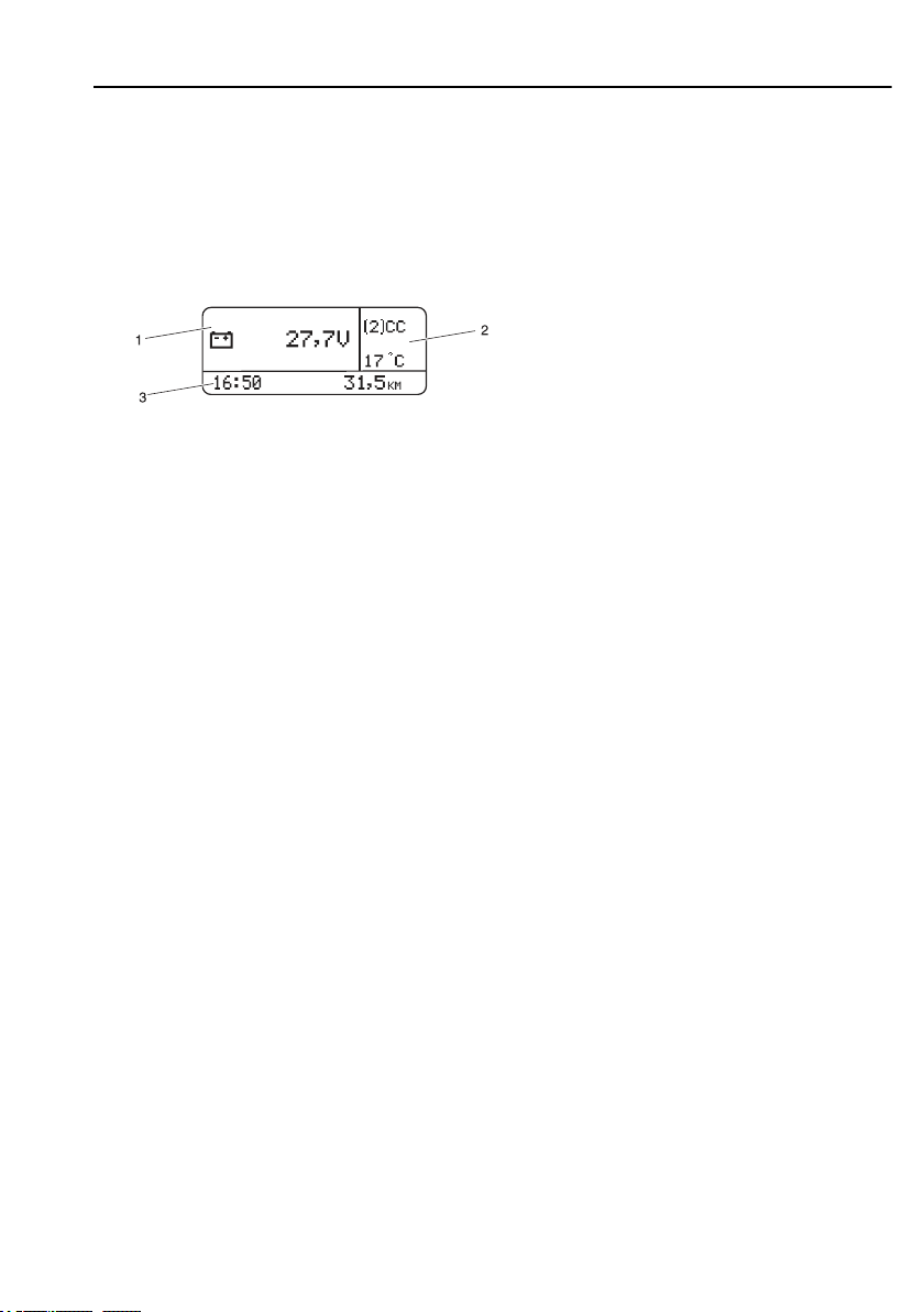
Information display
driver or workshop can obtain information, see section
"Display control stalk" for more information.
Display
The display is located in the middle of the the
instrument cluster. You can use the display to see
vehicle messages, control certain functions on the
truck and see information about the truck, amongst
them temperatures, levels and distances.
The display window is divided into three sectors:
1 Menu. This is where the menus are displayed,
together with automatic alarms, warnings and
information messages.
2 Status bar. The upper part displays the status
symbols. The lower part displays the outdoor
temperature.
3 Status bar. The clock is displayed on the left. The
odometer is displayed on the right.
81
J3018843
Page 93
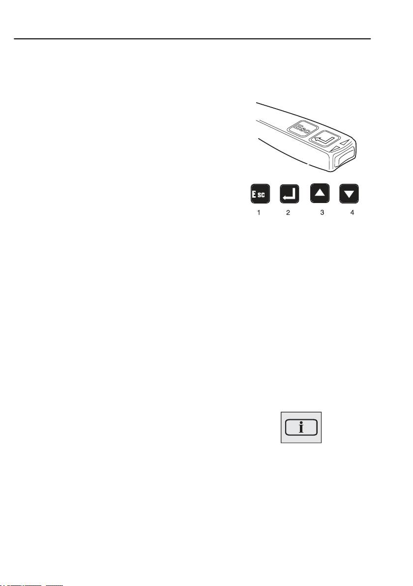
82
Information display
Display control stalk
In order to communicate with the display, the control
lever on the right hand side of the steering wheel is
used. The following commands are available:
1 “Esc” is used to return to the previous character
and to discontinue a setting/operation.
2 “SELECT” confirms a selection or a character.
3 “▲” is used for increasing values when setting
digits and for browsing in the diagnostics menus.
4 “▼” is used for reducing values when setting
digits and for browsing in the diagnostics menus.
General, about messages
There are three types of messages:
• Information
• Warning
• Stop
J3008810
Above the info display are three lamps (for
information, warning or stop messages) which attract
the driver's attention to faults in the vehicle.
Information messages
When this light comes on a new information message
is displayed. The lamp is used to inform the driver.
The lamp lighting does not indicate a fault in the
vehicle.
J3014366
Page 94
Information display
Warning messages
When this symbol lights up, the fault indicated should
be checked before driving. If no other warning lamp
lights to indicate the fault, contact the workshop. Fault
codes are obtained from the diagnostic menu, refer to
section “Fault diagnosis”.
Stop message
83
J3014365
Warning!
When this symbol lights up, the
vehicle should be stopped
immediately and the engine
switched off. If the vehicle is not
stopped and the engine turned off,
there will be serious
consequences for the vehicle,
driver or load. Contact a
workshop. Fault codes are
obtained from the diagnostic
menu, refer to section “Fault
diagnosis”.
Acknowledge messages
The message lamp goes out when ”Esc” is pressed.
Both warning and stop messages can be
acknowledged. Messages which have been
acknowledged but which are active are shown again
when the starter key is turned to starting position.
Warning message: Warning messages can be
acknowledged with ”Esc”. This warning is
J3014364
Page 95
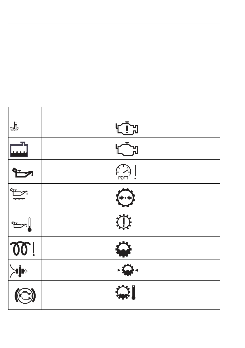
84
Information display
acknowledged until the next time the ignition key is
turned to the starter position. The warning message
and the symbol go out 30 seconds after the engine is
started.
Stop message: The buzzer is turned off with ”Esc”,
but is active again 10 seconds after the latest button
depression. The stop light remains lit the whole time.
Alarm, warning and information symbols
Symbol Meaning Symbol Meaning
High temperature, coolant Crankcase pressure too high
Low level, coolant Engine fault
Low oil pressure, engine oil Engine speed too high
Low oil level, engine oil Low air pressure, gearbox
High temperature,
engine oil
Air intake heating fault Low level, gearbox oil
High temperature,
inlet manifold
Engine temperature too
low for engine brake
(VEB)
Gearbox fault
Low oil pressure, gearbox
High temperature,
gearbox oil
Page 96
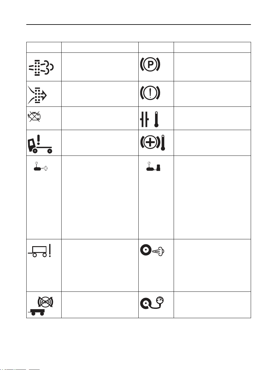
Information display
Symbol Meaning Symbol Meaning
85
Too high concentration of soot
particles or ash in the particulate
filter. See section “Particulate filter”
for more information.
Air filter clogged. Check that the net
in the air intake is not clogged.
Engine is switched off Clutch running hot
Cab tilt lock open Temperature, hydraulic
The compressor charge is unusually
high. The cause could be an air leak.
• If the symbol is shown together
with the information symbol (i),
the leak is so large that fuel
consumption
is increased.
• If the symbol is displayed
together with the check symbol
(CHECK), then the leak is so
large that it can cause an
unplanned stop if not remedied.
Parking brake applied
Brake pressure low
retarder
Risk of moisture in the pneumatic
system. There are several causes:
• Time to replace the desiccant
element.
• The compressor is being used to
much.
• Fault with the air system.
Fault in trailer EBS function Leakage from indicated tyre/axle.
Connected trailer without ABS High tyre pressure
This warning may also occur after
changing tyres. Disable by
unscrewing the hose to the tyre
pressure sensor on the tyre in
question, wait for a minute and then
screw on again. (Key in drive
position)
Page 97
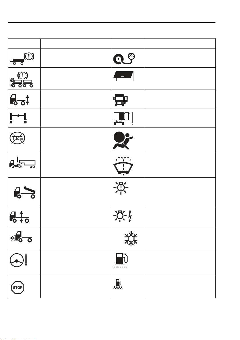
86
Symbol Meaning Symbol Meaning
Information display
Poor brake effect on
trailer
Uneven braking effect between
tractor and trailer
Low pressure in the air suspension
system
Wheel spin or ABS activated Door to cargo hold
Traction Control Function
temporarily disengaged
Trailer disconnected Low level washer fluid
Superstructure not in drive position One or more lamps do not light.
Air suspension in manual position Fault in the electrical system causing
Low tyre pressure
Baggage door open
Door open
open
Airbag
lamps not to light. Can cause a
hardware fault in the electronics.
Air suspension not in drive position Warning. Freezing conditions.
Low pressure or flow in steering
servo. The symbol might be
displayed when stationary or at low
speed without there being a fault.
Stop Low fuel level
Fuel filter clogged
Page 98
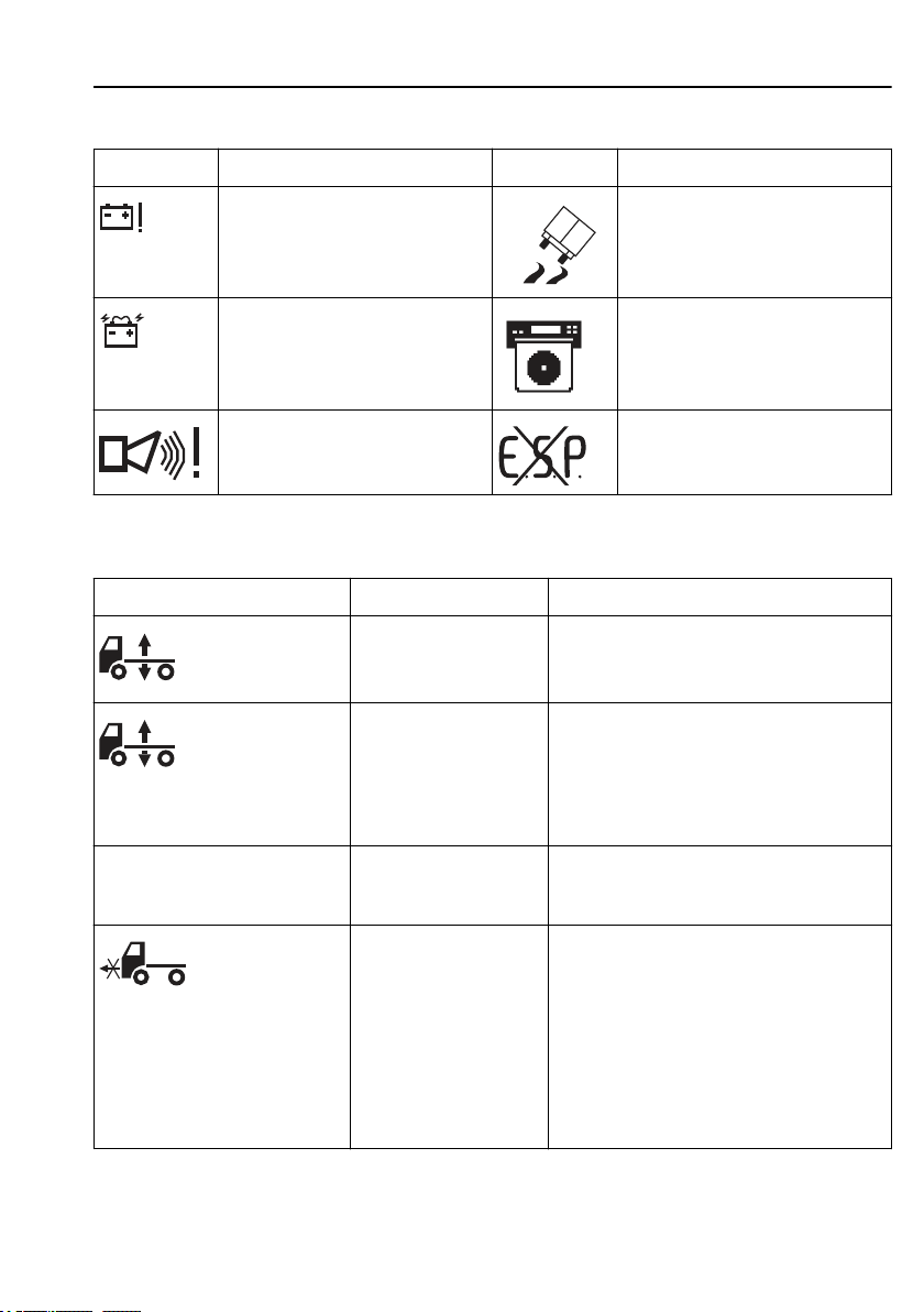
Information display
Symbol Meaning Symbol Meaning
Voltage warning Stability control active
87
Battery discharge Diagram sheet box open or sheet for
Alarm in service position. ESP (electronic stability program)
Symbols for air suspension
Symbol Meaning Action
The control button is set
to manual control or
adjustment of ride height.
If the control button is in
the centre position the air
suspension is in locked
position.
Axle load distribution 70% With "optimise traction",
the axle load distribution
is shown in the display.
Truck not in drive
position.
Select ride height
Note! Drive very carefully when the symbol is
displayed.
Check whether the air suspension is locked:
Turn the ignition key to the stop position (0)
and then back to the drive position (I).
If the symbol remains on the display the air
suspension is locked. See section "Air
suspension in locked position", page 628.
None. The message disappears when optimal
load distribution has been achieved.
Check that the control button is in the drive
position and wait until the truck reaches the
correct drive height.
Note! Drive very carefully when the symbol is
displayed.
A signal will sound if the speed is too high. If
a bellows is punctured, drive, at not more than
30 km/h
Volvo Action Service.
driver 1 missing. (Only for certain
variants)
temporarily disengaged
, to a Volvo workshop, or contact
Page 99
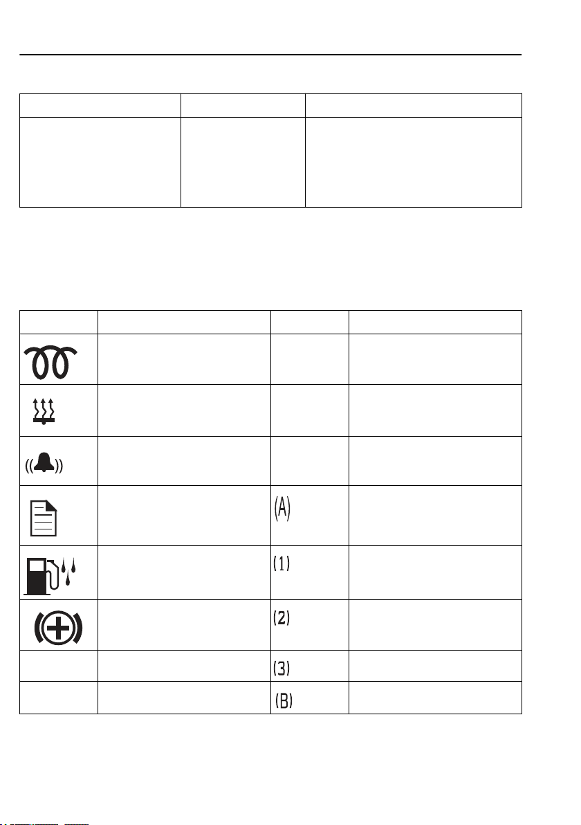
88
Symbol Meaning Action
Information display
CHECK THE AIR SUSPENSION
AT THE NEXT STOP
There is an air suspension
malfunction.
Check whether the fault is active at the next
stop: Turn the ignition key to the stop position
(0) and then back to the drive position (I). If
the message remains in the display, the fault is
active. See section "Air suspension in locked
position".
Status symbols
Status symbols are shown in the lowest row of the
display.
Symbol Meaning Symbol Meaning
Pre-heating active or pre-heating
fault
Parking heater timer activated CC Cruise control active
Alarm clock activated ACC Adaptive cruise control active
Message active Auxiliary brake position A
PTO Power take-off active
Water in fuel
(draining required)
Auxiliary brake in operation Auxiliary brake position 2
MI Odometer, miles Auxiliary brake position 3
KM Odometer, kilometres Auxiliary brake position B
Auxiliary brake position 1
Page 100
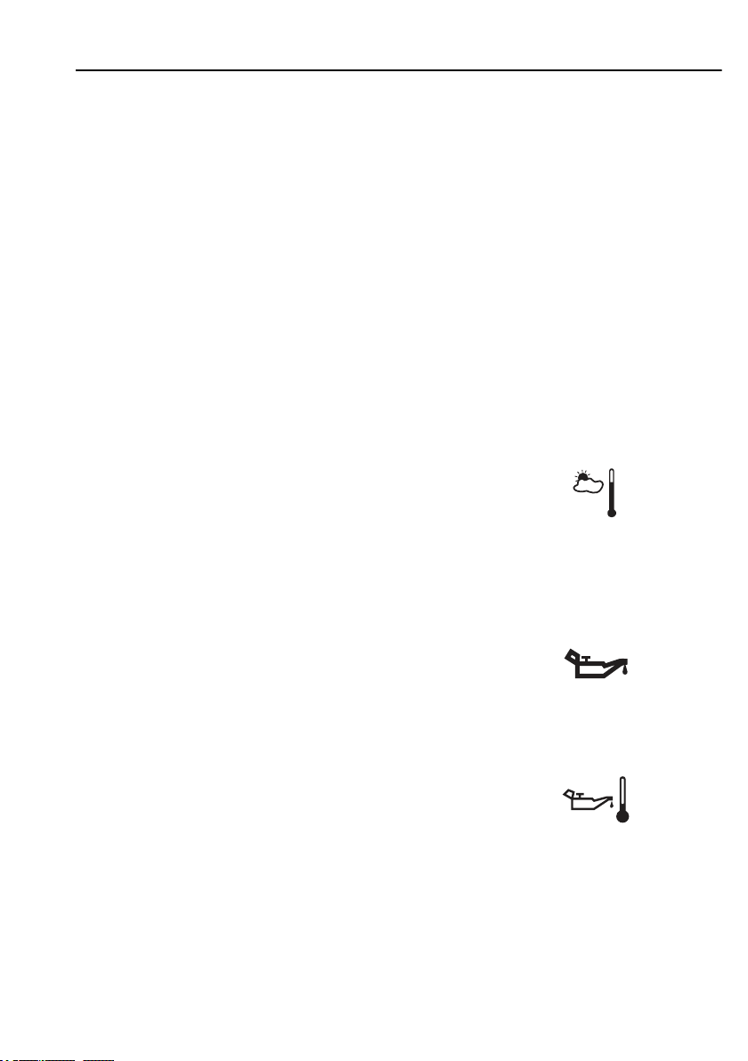
Information display
Other Symbols
There are even more symbols within different menus
that have not been included here. See the description
of the menu in question for an explanation.
Gear position
The menu "Gear position" shows information about
engaged gear, lever position, available gears etc.
For further information about ”Gearbox”, see separate
driver instructions ”
Temperature, outside
The temperature outside the cab.
I-shift
” and ”
Powertronic
”.
89
J3005101
Engine oil pressure
Oil pressure.
Temperature, engine oil
Temperature of the engine oil.
J3013611
 Loading...