


|
|
|
SECTION 01: ENGINE |
|
CONTENTS |
|
|||
1. |
VOLVO D13 ENGINE............................................................................................................................ |
3 |
||
|
1.1 |
SYSTEM OVERVIEW..................................................................................................................... |
3 |
|
|
1.2 |
ENGINE OVERVIEW...................................................................................................................... |
6 |
|
|
1.3 |
ENGINE OIL ................................................................................................................................... |
7 |
|
|
1.3.1 |
General.................................................................................................................................... |
7 |
|
|
1.3.2 |
Oil Quality ................................................................................................................................ |
7 |
|
|
1.3.3 |
Oil Change Intervals................................................................................................................ |
8 |
|
|
1.3.4 |
Oil Filters ................................................................................................................................. |
9 |
|
|
1.3.5 |
Synthetic Lubrication ............................................................................................................... |
9 |
|
|
1.3.6 |
Oil Viscosity............................................................................................................................. |
9 |
|
|
1.3.7 |
Oil Additives............................................................................................................................. |
9 |
|
|
1.3.8 |
Oil Consumption...................................................................................................................... |
9 |
|
|
1.3.9 |
Oil Change............................................................................................................................. |
10 |
|
|
1.3.10 |
Oil Filters Change.................................................................................................................. |
10 |
|
|
1.3.11 Checking The Oil Level ......................................................................................................... |
11 |
||
|
1.4 |
POWER PLANT ASSEMBLY REMOVAL..................................................................................... |
11 |
|
|
1.5 |
POWER PLANT ASSY. INSTALLATION...................................................................................... |
14 |
|
|
1.6 |
ENGINE MOUNTS ....................................................................................................................... |
14 |
|
2. DETROIT DIESEL SERIES 60 ENGINE............................................................................................. |
16 |
|||
|
2.1 |
DDEC VI SYSTEM........................................................................................................................ |
16 |
|
|
2.2 |
HARNESSES................................................................................................................................ |
16 |
|
|
2.3 |
ENGINE OVERVIEW.................................................................................................................... |
17 |
|
|
2.4 |
DDEC VI SENSORS..................................................................................................................... |
18 |
|
|
2.5 |
PREVOST INSTALLED SENSORS ............................................................................................. |
19 |
|
|
2.6 |
MOTOR CONTROL MODULE (MCM).......................................................................................... |
19 |
|
|
2.7 |
COMMON POWERTRAIN CONTROLLER (CPC) ....................................................................... |
19 |
|
|
2.8 |
DDEC VI DIAGNOSTICS.............................................................................................................. |
19 |
|
|
2.8.1 |
Diagnostic system ................................................................................................................. |
19 |
|
|
2.8.2 Check Engine Telltale Light (AWL) ....................................................................................... |
20 |
||
|
2.8.3 Stop Engine Warning Light (RSL) ......................................................................................... |
20 |
||
|
2.8.4 Stop Engine Override Switch (SEO) ..................................................................................... |
20 |
||
|
2.8.5 Diagnostic Data Link (DDL) Connectors ............................................................................... |
20 |
||
|
2.9 |
READING DIAGNOSTIC CODES – FLASHING LIGHT METHOD: ............................................. |
20 |
|
|
2.10 |
DDEC VI CPC DIAGNOSTIC CODES LIST ................................................................................. |
21 |
|
|
2.11 |
DDEC VI MCM DIAGNOSTIC CODES LIST ................................................................................ |
28 |
|
|
2.12 |
ENGINE OIL LEVEL ..................................................................................................................... |
39 |
|
|
2.13 |
ENGINE OIL AND FILTER CHANGE ........................................................................................... |
40 |
|
|
2.14 |
RECOMMENDED ENGINE OIL TYPE ......................................................................................... |
41 |
|
|
2.15 |
POWER PLANT ASSEMBLY REMOVAL..................................................................................... |
41 |
|
|
2.16 |
POWER PLANT ASSY. INSTALLATION...................................................................................... |
45 |
|
|
2.17 |
JAKE BRAKE................................................................................................................................ |
45 |
|
|
2.18 |
ENGINE MOUNTS ....................................................................................................................... |
45 |
|
3. ELECTRONIC FOOT PEDAL ASSEMBLY (EFPA) & THROTTLE POSITION SENSOR ................ |
46 |
|||
4. |
ENGINE TROUBLESHOOTING GUIDE............................................................................................. |
47 |
||
5. |
SPECIFICATIONS............................................................................................................................... |
49 |
||
|
5.1 |
SERIES 60 ENGINE ..................................................................................................................... |
49 |
|
|
5.2 |
VOLVO D13 ENGINE ................................................................................................................... |
50 |
|
PA1561 |
1 |

Section 01: ENGINE
ILLUSTRATIONS |
|
FIGURE 1: D13F ENGINE, ALTERNATOR SIDE (TYPICAL) ....................................................................................... |
6 |
FIGURE 2: D13F ENGINE, TURBO SIDE (TYPICAL) ................................................................................................ |
7 |
FIGURE 3: D13F OIL FILTERS............................................................................................................................. |
9 |
FIGURE 4: OIL FILTER WRENCH........................................................................................................................ |
10 |
FIGURE 5: OIL FITER REPLACEMENT................................................................................................................. |
11 |
FIGURE 6: ENGINE OIL FILLING TUBE ................................................................................................................ |
11 |
FIGURE 7: ENGINE OIL LEVEL DIPSTICK ............................................................................................................ |
11 |
FIGURE 8: BELT TENSIONER VALVE.................................................................................................................. |
12 |
FIGURE 9: ENGINE COMPARTMENT H3 COACHES (TYPICAL) ............................................................................... |
14 |
FIGURE 10: VOLVO ENGINE POWER PLANT CRADLE INSTALLATION ..................................................................... |
15 |
FIGURE 11: VEHICLE INTERFACE HARNESS (GENERAL APPLICATION SHOWN)...................................................... |
16 |
FIGURE 12: DETROIT DIESEL 2007 SERIES 60 ENGINE (TYPICAL ........................................................................ |
18 |
FIGURE 13: MOTOR CONTROL MODULE (MCM).................................................................................................. |
19 |
FIGURE 14: CPC............................................................................................................................................. |
19 |
FIGURE 15: THE CPC COMMUNICATES OVER THE J1587 AND J1939 DATA LINKS TO THE VEHICLE ........................ |
19 |
FIGURE 16: FLASHING FAULTS CODES ............................................................................................................. |
21 |
FIGURE 17: ENGINE OIL LEVEL DIPSTICK .......................................................................................................... |
39 |
FIGURE 18: OIL RESERVE TANK ....................................................................................................................... |
39 |
FIGURE 19: UNDER VEHICLE VIEW ................................................................................................................... |
40 |
FIGURE 20: ENGINE COMPARTMENT ................................................................................................................ |
42 |
FIGURE 21: ENGINE COMPARTMENT H3 COACHES (TYPICAL) ............................................................................. |
44 |
FIGURE 22: ENGINE COMPARTMENT VIP (TYPICAL)............................................................................................ |
44 |
FIGURE 23: POWER PLANT CRADLE INSTALLATION ............................................................................................ |
45 |
FIGURE 24: ELECTRONIC FOOT PEDAL ASSEMBLY............................................................................................. |
46 |
PA1561 |
2 |

Section 01: ENGINE
1. VOLVO D13 ENGINE
1.1 SYSTEM OVERVIEW
NOTE
The “Premium Tech Tool” (PTT) is the preferred tool for performing diagnostic work. Contact your local dealer for more information.
The Engine Management System (EMS) controls many engine functions such as: fuel timing and delivery, engine protection functions, engine brake operation, EGR valve function and the turbocharger nozzle function. The Engine Electronic Control Unit (EECU) along with other supporting control units and sensors are responsible for monitoring and controlling these functions. These control units communicate through the J1939 high speed serial data line to share data.
In addition to their control functions, the modules have on-board diagnostic capabilities. The onboard diagnostics are designed to detect faults or abnormal conditions that are not within their operating parameters. When the system detects a fault or abnormal condition, the fault will be logged in one or both of the modules’ memory. The vehicle operator will be advised that a fault has occurred by the illumination of a malfunction indicator lamp and a message in the driver information display, if equipped. The module may initiate the engine shutdown procedure if the system determines that the abnormal condition could damage the engine. In some situations, the system will enter the "limp home" mode. Limp home mode allows continued vehicle operation but, the system may substitute a sensor or signal value that may result in reduced engine performance.
Fault codes logged in the system memory, can later be read to aid in diagnosing the fault. These faults can be read via a diagnostic computer or through the instrument cluster display, if equipped. The “Premium Tech Tool” (PTT) is the preferred tool for performing diagnostic work. Using a diagnostic computer (or PTT) connected to the Serial Communication Port, expands the technicians diagnostic capabilities with additional data and tests.
For diagnostic software, contact your local dealer.
The following is a list of engine sensors that
PA1561 |
3 |
provide input to the EMS:
•Ambient Air Temperature Sensor
•Ambient Pressure sensor
•Boost Air Pressure (BAP) Sensor
•Camshaft Position (Engine Position) Sensor
•Crankshaft Position (Engine Speed) Sensor
•Differential Pressure DPF Sensor
•EGR Differential Pressure Sensor
•EGR Temperature Sensor
•Engine Coolant Level (ECL) Sensor
•Engine Coolant Temperature (ECT) Sensor
•Engine Oil Pressure (EOP) Sensor
•Engine Oil Level (EOL) Sensor
•Engine Oil Temperature (EOT) Sensor
•Exhaust Temperature Sensor (DPF Sensors)
•Fuel Pressure Sensor
•Intake Air Temperature And Humidity (IATH) Sensor
•Intake Manifold (Boost) Temperature Sensor
•Throttle Position (TP) Sensor
•Turbo Speed Sensor
•Variable Geometry Turbocharger (VGT) Position Sensor
Sensors
Ambient Air Temperature Sensor
The Ambient Air Temperature Sensor is used to detect the outside air temperature. The sensor modifies a voltage signal from the ECM. The modified signal returns to the ECM as the ambient air temperature. The sensor uses a thermistor that is sensitive to the change in temperature. The electrical resistance of the thermistor decreases as temperature increases.
The Ambient Air Temperature Sensor is located in the front of the vehicle.
Ambient (Atmospheric) Pressure Sensor
The Ambient (Atmospheric) Pressure Sensor contains a pressure sensitive diaphragm and an electrical amplifier. Mechanical pressure applied

Section 01: ENGINE
to the diaphragm causes the diaphragm to deflect and the amplifier to produce an electrical signal proportional to the deflection.
The Ambient (Atmospheric) Pressure Sensor is built into the Engine Management System (EMS) Module.
Camshaft Position Sensor
The Camshaft Position (Engine Position) Sensor is located in the rear face of the timing gear cover at the rear of the engine, near the bottom of the valve cover. It uses magnetic induction to generate a pulsed electrical signal. It senses the passage of seven (7) timing bumps on the edge of the camshaft dampener. Six of the holes correspond to the phasing of the electronic unit injectors, while the seventh hole indicates the top dead center position.
Crankshaft Position (Engine Speed) Sensor
The Crankshaft Position (Engine Speed) Sensor uses magnetic induction to generate a pulsed electrical signal. Notches are machined into the edge of the flywheel. When one of the notches passes close to the sensor, electric pulses result.
The Crankshaft Position (Engine Speed) Sensor also indicates when the crankshaft is at the top dead center position.
Differential Pressure DP Sensor
The differential pressure sensor is used for flow measurement of the Diesel Particulate Filter (DPF). This sensor has two pressure ports and senses the difference in pressure between the two ports. Measurement of the pressure before and after the DPF is used to calculate diesel filter regeneration.
The Differential Pressure DPF Sensor is located on the side of the Diesel Particulate Filter (DPF).
EGR Differential Pressure Sensor
The EGR differential pressure sensor is used for flow measurement of the Exhaust Gas Recirculation (EGR) valve. This sensor has two pressure ports and senses the difference in pressure between the two ports. Measurement of the pressure before and after the EGR valve is used to calculate EGR flow.
The EGR Differential Pressure Sensor is located on the left or right side of the engine.
PA1561 |
4 |
EGR Temperature Sensor
The EGR temperature sensor detects exhaust gas temperature for EGR system. The sensor modifies a voltage signal from the control unit. The modified signal returns to the control unit as the exhaust temperature of the EGR system to confirm EGR operation. The sensor uses a thermistor that is sensitive to the change in temperature.
The EGR Temperature Sensor is located near the EGR valve.
Engine Coolant Level (ECL) Sensor
The Engine Coolant Level (ECL) Sensor is a switch. If engine coolant level falls below a calibrated point the contacts open and the driver will be notified of the low coolant level.
The Engine Coolant Level (ECL) Sensor is located in the cooling system reservoir tank.
Engine Coolant Temperature (ECT) Sensor
The Engine Coolant Temperature Sensor is located at the front of the engine. The sensor will indicate a high coolant temperature caused by problems like radiator blockage, thermostat failure, heavy load, or high ambient temperatures. This sensor is also used for cold start enhancement and for fan clutch engagement.
Engine Oil Pressure (EOP) Sensor
The Engine Oil Pressure Sensor contains a pressure sensitive diaphragm and a electrical amplifier. Mechanical pressure applied to the diaphragm causes the diaphragm to deflect and the amplifier to produce an electrical signal proportional to the deflection.
The Engine Oil Pressure Sensor is located on the oil filter assembly. The sensor monitors engine oil pressure to warn of lubrication system failure.
Engine Oil Level (EOL) Sensor
The Engine Oil Level Sensor is located in the oil pan.
Engine Oil Temperature (EOT) Sensor
The Engine Oil Temperature Sensor is a thermistor whose resistance varies inversely to temperature. The sensor has a negative

Section 01: ENGINE
temperature coefficient, which means the sensor resistance will decrease as the engine oil temperature increases.
The Engine Oil Temperature Sensor is located in the oil pan.
Exhaust Temperature Sensor (DPF Sensors)
The exhaust gas temperature sensor detects exhaust gas temperature for DPF protection as well as DPF regeneration control. The sensor modifies a voltage signal from the control unit. The modified signal returns to the control unit as the exhaust temperature at that specific location of the exhaust. The sensor uses a thermistor that is sensitive to the change in temperature.
The Exhaust Temperature Sensors are located in the DPF assembly.
Fuel Pressure Sensor
The fuel pressure sensor contains a diaphragm that senses fuel pressure. A pressure change causes the diaphragm to flex, inducing a stress or strain in the diaphragm. The resistor values in the sensor change in proportion to the stress applied to the diaphragm and produces an electrical output.
The Fuel Pressure Sensor is located on top of the fuel filter housing.
Intake Air Temperature and Humidity (IATH) Sensor
The Intake Air Temperature and Humidity (IATH) Sensor contains a thermistor and a capacitive sensor. The resistance of the thermistor varies inversely to temperature. The output of the capacitive sensor increases as the humidity of the surrounding air increases. By monitoring the signals from both portions of the sensor, the Engine Management System (EMS) Module calculates the temperature and humidity of the air passing through the air filter housing.
The Intake Air Temperature and Humidity (IATH) Sensor is located in the air intake tube just downstream from the air filter canister.
Intake Manifold (Boost) Temperature Sensor
The Intake Manifold (Boost) Temperature Sensor is a thermistor whose resistance varies inversely to temperature. The sensor has a negative temperature coefficient, which means the sensor resistance will decrease as the inlet
PA1561 |
5 |
air temperature increases.
The Intake Manifold (Boost) Temperature Sensor is located in the intake manifold.
Intake Manifold Pressure Sensor
The Intake Manifold Pressure Sensor contains a pressure sensitive diaphragm and an electrical amplifier. Mechanical pressure applied to the diaphragm causes the diaphragm to deflect and the amplifier to produce an electrical signal proportional to the deflection.
The Intake Manifold Pressure Sensor is located on the air inlet pipe before the intake manifold.
Throttle Position (TP) Sensor
The Throttle Position Sensor is a potentiometer that is mechanically linked to the accelerator pedal. A potentiometer is a variable resistor whose resistance will change as the pedal is pressed. As the resistance changes, the signal voltage of the sensor changes indicating the accelerator pedal position.
The Throttle Position Sensor is located above the accelerator pedal. The sensor is designed to improve the driver’s control by reducing sensitivity to chassis motion. This sensor provides the driver’s fuel request input to the VECU.
Turbo Speed Sensor
The Turbo Speed Sensor informs the EMS of the turbo shaft speed. The sensor does not read from the vanes, but reads from the shaft. The Engine Management System (EMS) Module uses this signal in conjunction with the VGT position sensor signal to control the speed of the turbocharger and therefore optimize the intake manifold pressure.
The Turbo Speed Sensor is mounted in the center of the turbocharger.
Variable Geometry Turbocharger Smart Remote Actuator (VGT SRA)
The Variable Geometry Turbocharger Smart Remote Actuator (VGT SRA) takes the position commands from the EMS, moves the nozzle of the turbocharger to the desired position, and performs all of the diagnostics and self checks on the actuator.

Section 01: ENGINE
1.2 ENGINE OVERVIEW
NOTE
For additional information concerning Volvo D13 engine components or engine-related components, consult Volvo Trucks Canada or Volvo Trucks North America Web Site under: Parts & Service. On Volvo web site, you will find detailed service procedures for parts replacement, repair and maintenance.
FIGURE 1: D13F ENGINE, ALTERNATOR SIDE (TYPICAL)
1. |
Breather Tube |
7. |
Fuel Filter |
2. |
Intake Manifold |
8. |
Fuel/Water Separator |
3. |
Air Compressor |
9. |
Fuel Filter |
4. |
Power Steering Pump |
10. |
Hand-Priming Pump |
5. |
Fuel Pump |
11. Crankcase Ventilator |
|
6. |
Engine Electronic Control Unit (EECU) |
12. |
EGR Mixing Chamber |
PA1561 |
6 |
Section 01: ENGINE
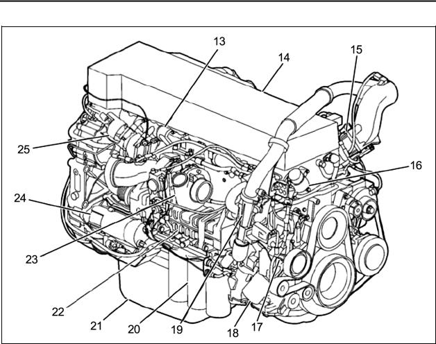
FIGURE 2: D13F ENGINE, TURBO SIDE (TYPICAL)
13. |
Exhaust Manifold |
20. |
Oil Filters |
14. |
Valve Cover |
21. |
Oil Pan |
15. |
Engine Pre-Heater Element (Optional) |
22. |
EGR Cooler |
16. |
DRV Valve |
23. Turbocharger |
|
17. |
Coolant Pump |
24. |
Starter Motor |
18. |
Coolant Filter |
25. |
EGR Valve |
19. |
Venturi Pipe |
|
|
1.3 |
ENGINE OIL |
|
|
1.3.1 General
Keep the engine oil at the proper level and change it at the recommended intervals. Always replace the oil filters at the same time as when the oil is changed.
1.3.2 Oil Quality
Volvo North America recognizes engine oils that meet or exceed the standards given by American Petroleum Institute (API) for the oil classifications listed in this manual. Only oils licensed to carry the API
PA1561 |
7 |
Section 01: ENGINE
symbol should be used. Lubricants meeting API standards have provided maximum engine life when used together with the recommended oil and oil filter change intervals.
EO-O Premium Plus (or VDS-4) diesel engine oil is mandatory for use in all 2007 emission compliant Volvo engines. Chassis equipped with a 2007 emission compliant engine, which can be identified by the presence of a Diesel Particulate Filter (DPF), also require the use of Ultra Low Sulfur Diesel (ULSD) fuel. EO-O Premium Plus oils exceed the new API service category CJ-4.
CAUTION
DO NOT add extra oil additives. Additives such as break-in oils, top oils, graphitizers, and frictionreducing liquids are not necessary and can harm the engine.
1.3.3 Oil Change Intervals
The length of time an engine can operate before an oil change depends on the quality oil used, the type of fuel used, fuel consumption, engine oil consumption, vehicle application, level of dust in the air, and fuel consumption. The change intervals given in this manual are maximum intervals. If the vehicle is operating in heavy-duty operation, dusty or off-road conditions, etc., reduce the intervals for more frequent oil changes.
NOTE
Use the information in the table below to determine the operating condition and usage applicable to your vehicle.
Engine Operating Condition |
Medium |
Heavy |
Severe |
|
|
|
|
Total Fuel Consumption (mpg) |
More than 6 |
More than 4.7 |
More than 3.7 |
|
|
|
|
Total Fuel Consumption (L/100 KM) |
Less than 39 |
Less than 50 |
Less than 64 |
|
|
|
|
Engine Oil and Filter Change |
35,000 (55 000) |
25,000 (40 000) |
15,000 (24 000) |
Interval, miles (km) – 41 U.S. quarts (39L) |
|
|
|
Oil capacity |
|
|
|
|
|
|
|
NOTE: If idle time is greater than 25%, use the next lower drain interval.
PA1561 |
8 |
Section 01: ENGINE
NOTE
Oil filters should always be changed when changing the oil.
1.3.4 Oil Filters
There are three filters on the engine, one of which is a bypass filter. This should be changed at the same time as the full-flow filter(s).
CAUTION
Volvo branded oil filters are designed to provide the proper level of filtration and protection for Volvo engines. Filters that do not meet the same stringent requirements may void engine warranty.
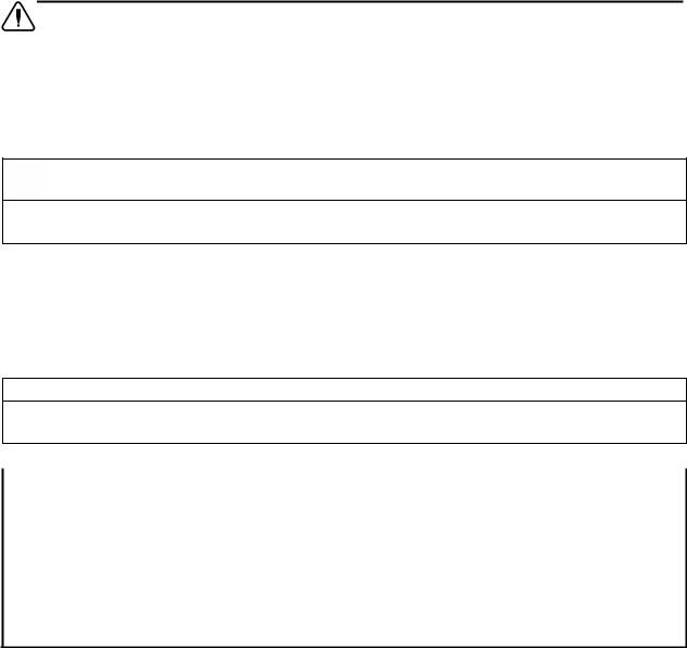
Choose the viscosity grade for the typical ambient temperature for the application. Multigrade oils have a broad range that suit operation in changing temperature.
Volvo North America recommends the viscosities shown in the viscosity/temperature table for Volvo engines.
FIGURE 3: D13F OIL FILTERS
1.3.5 Synthetic Lubrication
Synthetic oils are offered by some oil suppliers as an alternative to the traditional, petroleum based oils for engines. These oils may be used in Volvo engines, provided they meet the quality levels specified on the previous pages, that is: both VDS-4 and EO-O Premium Plus.
The use of synthetic oils does not permit the extension of the recommended oil change intervals.
1.3.6 Oil Viscosity
The viscosity grade defines the thickness of the oil. The oil must be thin enough at low temperatures for easy cold starts and thick enough to protect at high temperatures. An oil is not fully defined until both the API quality classification and the viscosity grade are specified.
PA1561 |
9 |
1.3.7 Oil Additives
CAUTION
Extra oil additives must never be added to any engine oil used. Additives such as breakin oils, top oils, graphitizers, and friction reducing liquids are not necessary and may even harm the engine.
Using oils to the quality standards recommended in this manual makes the use of extra oil additives unnecessary, as these oils already contain a balanced treatment of additives.
1.3.8 Oil Consumption
Once the engine is stopped, check the oil level daily. If the engine has just been stopped and it is warm, wait approximately five minutes to allow the oil to drain back to the oil pan before checking. Add oil as necessary.
CAUTION
DO NOT overfill engine with oil.
All diesel engines are designed to consume some oil, so it is normal to add oil periodically. An engine used in heavy-duty operation will consume more oil than one in normal operation.
Section 01: ENGINE
1.3.9 Oil Change |
1.3.10 Oil Filters Change |
 WARNING
A hot engine or engine oil can be dangerous. Serious burns can result from contact with a hot engine or oil. Take precautions when draining the oil. Wear gloves or let the engine cool down before draining.
 WARNING
When draining the oil, use the proper tools and keep away as far as possible. Raise the elbow so the forearm is parallel to the ground to prevent oil running down the arm, causing burns.
CAUTION
Always dispose of all lubricants (motor oil, coolant, gear box oils, etc) and filters according to Federal or local regulations. Used oil disposed of in nature or waterways contaminates our drinking water and kills wildlife.
 WARNING
Prolonged contact with used engine oil may be harmful. Use rubber gloves when handling used oil. Wash skin thoroughly if it comes in contact with used oil.
It is important to drain as much oil as possible. Try to change oil immediately after driving, when the oil is warm. Always replace the oil filters when changing the oil.
Component |
Capacity (L) |
Oil pan |
24 min - 32 max |
|
|
Engine block |
4.5 |
|
|
Filters (3) |
6 |
|
|
Total oil fill (empty) |
42.5 |
|
|
NOTE
Since about 1 liter of oil remains in the engine after draining, approximately 38 liters will be needed for a complete oil change.
 WARNING
Hot oil can cause severe burns. DO NOT allow hot oil to contact the skin. When changing oil, wear protective gloves.
CAUTION
Volvo-branded oil filters are designed to provide the proper level of filtration and protection for Volvo engines. Filters that do not meet the same stringent requirements may cause unsatisfactory results.
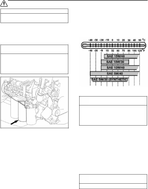
•Clean around the oil filter housing and remove the filters using the oil filter wrench or the oil filter socket.
FIGURE 4: OIL FILTER WRENCH
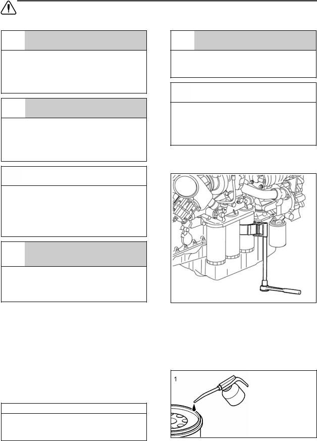
•Prefill the new oil filters with approved engine oil. Also, lubricate the filter gaskets with engine oil (1). Hand tighten the oil filters until they contact the sealing surface of the oil filter housing (2). Manually tighten the oil filters an additional ¾ to 1 full turn (3).
PA1561 |
10 |
Section 01: ENGINE
FIGURE 5: OIL FITER REPLACEMENT
•Start the engine and check for leaks around the oil filter housing and filters.
•Check the oil level. Add approved engine oil to the recommended level, if necessary. Do not overfill.
1.3.11 Checking the Oil Level
Ensure that the vehicle is parked on level ground before checking the oil level. Wait five minutes after shutting off the engine and then proceed with checking the oil.
FIGURE 6: ENGINE OIL FILLING TUBE
FIGURE 7: ENGINE OIL LEVEL DIPSTICK
1.4 POWER PLANT ASSEMBLY REMOVAL
To access the engine or engine-related components, the vehicle power plant assembly must be removed as a whole unit by means of a slide-out cradle. The power plant assembly includes the engine, transmission (including retarder if so equipped), air compressor, alternator and transmission oil cooler.
Remove the power plant assembly as follows:
CAUTION
DO NOT let the oil level fall below the marking on the dipstick. DO NOT overfill so the level is above the upper marking on the dipstick. This could lead to excessive oil temperature and/or poor crankcase breather performance. Add oil through the oil filler pipe as required in order to maintain level within the safe range.
CAUTION
Tag hoses and cables for identification before disconnecting in order to facilitate reinstallation. Plug all openings to prevent dirt from entering the system.
NOTE
No parts within the EECU are serviceable. If found defective, replace the EECU as a unit.
• Preparation
1.Close the heater lines shut-off valves.
2.Disconnect the battery or batteries from the starting system by removing one or both of the battery cables from each battery system. With the electrical circuit disrupted, accidental contact with the starter button will not produce an engine start.
PA1561 |
11 |
Section 01: ENGINE
 WARNING
Due to the heavy load of the rear bumper assembly, it must be adequately supported before attempting to remove it.
9.Disconnect and remove the air intake duct mounted between the turbocharger outlet and the air cooler inlet.
10.Disconnect and remove section of coolant pipe assembly mounted between the radiator outlet and the water pump inlet.
3.Remove the rear bumper assembly from the vehicle. Refer to Section 18 BODY, under "Rear Bumper Removal".
4.If applicable, disconnect the block heater connector located near the EGR mixing chamber.
|
|
|
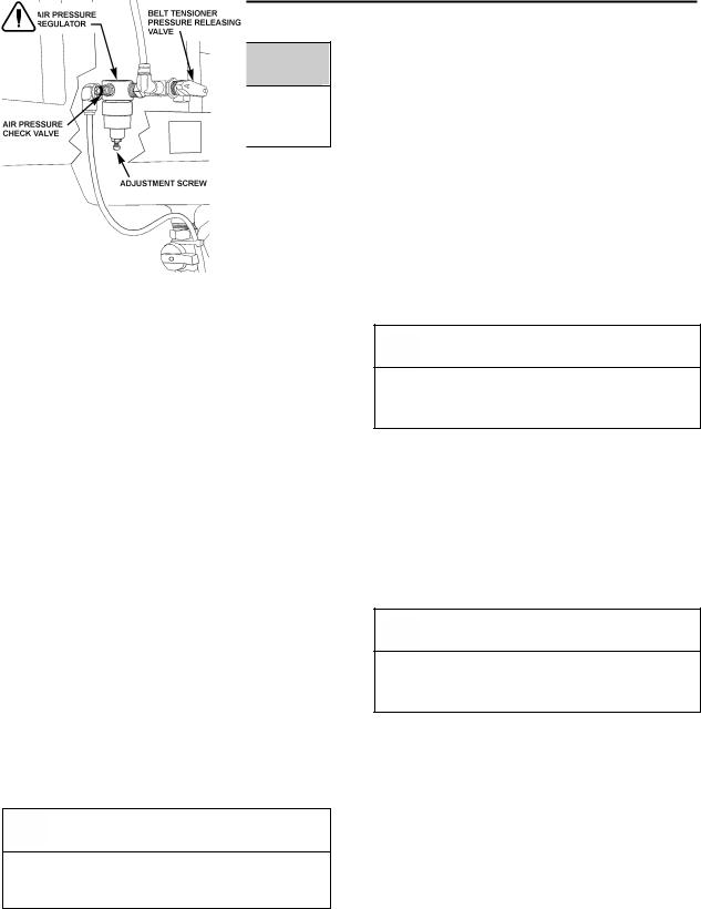
FIGURE 8: BELT TENSIONER VALVE |
12200 |
|
5.Locate the A/C compressor belt tensioner pressure releasing valve (Fig. 8). Turn pressure releasing valve handle counterclockwise in order to release pressure in belt-tensioner air bellows and loosen belt. Remove the A/C compressor belt.
6.To release all pressure from the air system. Refer to Section 12, BRAKES & AIR SYSTEM for instructions.
7.Disconnect and remove the engine-air intake duct mounted between air cleaner housing and turbocharger inlet.
CAUTION
To avoid damage to turbocharger, cover the turbocharger inlet opening to prevent foreign material from entering.
8.Disconnect and remove the air intake duct mounted between the air cooler outlet and the engine intake.
11.Disconnect and remove a section of coolant pipe assembly mounted between the thermostat housing and the radiator inlet, if applicable.
12.Disconnect the electric fan-clutch connector located near the cooling fan right angle gearbox.
13.Disconnect the cooling fan drive shaft.
CAUTION
To avoid damage to cooling fan right angle gearbox, make sure the power plant cradle clears the gearbox when pulling the engine out.
14.Disconnect surge tank hoses connected to the thermostat housing, the pump inlet and to the transmission oil cooler.
15.Disconnect and remove the exhaust pipe mounted between the flexible coupling and the pipe going to the Aftertreatment Device (ATD). If necessary, refer to Section 04 EXHAUST SYSTEM under “Muffler Removal and Installation".
CAUTION
To avoid damage to turbocharger, cover the turbocharger outlet opening to prevent foreign material from entering.
16.Remove the power steering pump.
17.Close engine fuel supply shutoff valve on primary fuel filter or Fuel Pro. Disconnect the fuel line located above fuel filters and connected to inlet port. On vehicles equipped with the optional fuel filter/water separator, disconnect the connector and remove cable ties from cradle.
• With Vehicle Raised
18. Using the quick-connect drain hose, drain the engine cooling system. Refer to Section 05 COOLING under "Draining Cooling System".
PA1561 |
12 |
Section 01: ENGINE
19. From under the vehicle, disconnect the propeller shaft as detailed in Section 09, under heading "Propeller Shaft Removal".
20.On vehicles equipped with an automatic transmission provided with a hydraulic output retarder, disconnect steel-braided airline from pressure regulator output. The pressure regulator is mounted in the upper section of engine compartment backwall and is accessible through the engine compartment R.H. side door.
21.Remove the retaining bolts, washers and nuts securing the power plant cradle to the vehicle rear subframe.
22.Disconnect transmission harness from transmission housing.
• With Vehicle Lowered
23.Disconnect the air compressor discharge, governor steel-braided airlines and manual filling airlines from compressor. Remove retaining clips.
24.Disconnect the hose connecting the compressor head to the sump tank, if applicable.
25.Disconnect ground cables from rear subframe ground-stud located close to the starter motor.
26.Disconnect alternators cooling duct and put aside.
27.Inside rear electrical compartment, disconnect starter, alternators and heater cables. Also disconnect AFSS cable if applicable.
28.Disconnect Aftertreatment Device (ATD) control cable.
29.Disconnect VIH (vehicle interface harness) connector.
30.Disconnect fuel return line from bulkhead fixed on engine cylinder head end.
31.Unfasten and put aside engine compartment lighting fixture and turbocharger fire suppression nozzle if applicable.
32.Disconnect turbo boost pressure gauge airline from engine air intake, if applicable.
33. Disconnect the engine coolant hose near the starter.
34.On partition wall, disconnect connector C397 located between engine compartment and main power compartment.
35. Inspect the power plant assembly to ensure that nothing will interfere when sliding out the cradle. Check for connections or hoses not mentioned in this list as some vehicles are equipped with special or aftermarket components.
NOTE
Check if any spacer(s) have been installed between power plant cradle and vehicle rear subframe, and if so, note position of each washer for reinstallation purposes.
36.Using a forklift, with a minimum capacity of 4,000 lbs (1 800 kg), slightly raise the power plant cradle.
37.Pull engine out slowly from the engine compartment. Make sure all lines, wiring and accessories are disconnected and are not tangled.
CAUTION
Due to the minimum clearance between the power plant equipment and the top of the engine compartment, extreme care should be used to raise the power plant cradle, just enough to free the cradle. Clearance between power plant cradle and mounting rail should range between ¼" and ½" (6-12 mm).
PA1561 |
13 |
Section 01: ENGINE
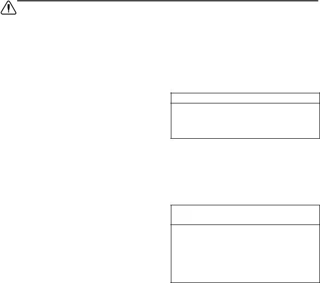
FIGURE 9: ENGINE COMPARTMENT H3 COACHES (TYPICAL)
1.5 POWER PLANT ASSY. INSTALLATION
To install a power plant assembly, follow the same procedure as in "Power Plant Assembly Removal" except in reverse order, then proceed with the following:
1.Torque the power plant cradle mounting bolts to 190 lbf-ft (255 Nm).
2.Refill cooling system with saved fluid (refer to Section 05 COOLANT SYSTEM).
3.Once engine fuel system has been drained, it will aid restarting if fuel filters are filled with fuel oil (refer to Section 03 FUEL SYSTEM).
4.Start engine for a visual check. Check fuel, oil, cooling, pneumatic and hydraulic system connections for leakage. Test operation of engine controls and accessories.
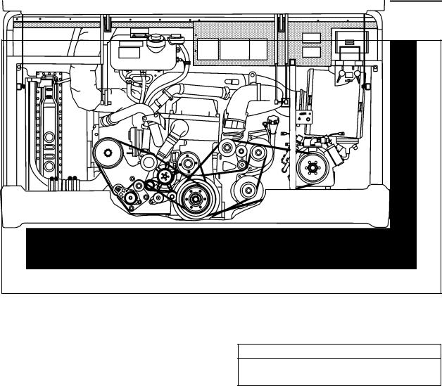
1.6 ENGINE MOUNTS
The power plant assembly is mounted to the cradle by means of rubber mounts and supports.
Two engine support brackets are used at the front of the engine while two rubber mounts are mounted underneath the engine & radiator fan drive mechanism support and the engine & alternator support (Fig. 10).
01193
It is recommended that new rubber mounts be installed at each major overhaul.
NOTE
Refer to the table on the following page for engine cradle tightening torques.
PA1561 |
14 |
Section 01: ENGINE
FIGURE 10: VOLVO ENGINE POWER PLANT CRADLE INSTALLATION
DRY TORQUES
|
REFERENCE |
DESCRIPTION |
|
Lbf-ft |
Nm |
|
|
A |
SCREW, CAP HEXAGONAL HEAD M8 – 1.25 |
G8.8 |
16 |
22 |
|
|
B |
SCREW, CAP HEXAGONAL HEAD M8 – 1.25 |
G10.9 |
22 |
30 |
|
|
C |
SCREW, CAP HEXAGONAL HEAD M10 – 1.5 |
G10.9 |
43 |
58 |
|
|
D |
SCREW, CAP HEXAGONAL HEAD M12 – 1.75 |
G8.8 |
60 |
81 |
|
|
E |
SCREW, CAP HEXAGONAL HEAD M14 – 2.0 |
G8.8 |
90 |
122 |
|
|
F |
SCREW, CAP HEXAGONAL HEAD M16 – 2.0 |
G8.8 |
140 |
190 |
|
|
G |
SCREW, CAP HEXAGONAL HEAD M16 – 2.0 |
G10.9 |
190 |
258 |
|
|
H |
SCREW, CAP HEXAGONAL HEAD M20 – 2.5 |
G10.9 |
450 |
610 |
|
|
|
|
|
|
|
|
PA1561 |
15 |
Section 01: ENGINE
2. DETROIT DIESEL SERIES 60 ENGINE
The DDC series 60 engine is a 6-cylinder, fourcycle, 14.0 liters Detroit Diesel series 60 engine, equipped with an electronic control system (DDEC VI).
Complete maintenance and repair information on the engine will be found in the current
DETROIT DIESEL SERIES 60 2007 ONHIGHWAY SERVICE MANUAL 6SE2007. This essential manual contains complete instructions on operation, adjustment (tune-up), preventive maintenance and lubrication, parts verification, repair or replacement. This manual’s sections cover complete systems such as:
•Engine main assembly;
•Fuel system;
•Lubrication system;
•Cooling system;
•Fuel, lubricating oil and coolant;
•Air intake system;
•Exhaust system;
•Exhaust gas recirculation components;
•Electrical equipment;
•Operation and verification;
•Engine tune-up;
•Preventive maintenance;
•Storage;
Refer to Series 60 DDEC VI Troubleshooting Guide published by Detroit Diesel for more complete information on diagnosis of components and system problems.
Procedures for engine removal and installation are given at the end of this section. The DDEC system is self-diagnostic. It can identify faulty components and other engine-related problems by providing the technician with diagnostic codes.
2.1 DDEC VI SYSTEM
DDEC VI (Detroit Diesel Electronic Control) is a system that monitors and determines all values required for the operation of the engine. A diagnostic interface is provided to connect to an external diagnosis tester. Besides the engine related sensors and the engine-resident control unit, the Motor Control Module (MCM), this
PA1561 |
16 |
system has a chassis-mounted control unit for vehicle engine management, the Common Powertrain Controller (CPC). The connection to the vehicle is made via a CAN interface which digitally transmits the nominal values (e.g. torque, engine speed specification, etc.) and the actual values (e.g. engine speed, oil pressure, etc.).
DDEC VI controls the timing and amount of fuel injected by the electronic unit injectors (EUI). The system also monitors several engine functions using electrical sensors, which send electrical signals to the Motor Control Module (MCM). The MCM computes the electrical signals and determines the correct fuel output and timing for optimum power, fuel economy and emissions. The MCM also has the ability to display warnings or shut down the engine completely (depending on option selection) in the event of damaging engine conditions, such as low oil pressure or high engine temperature.
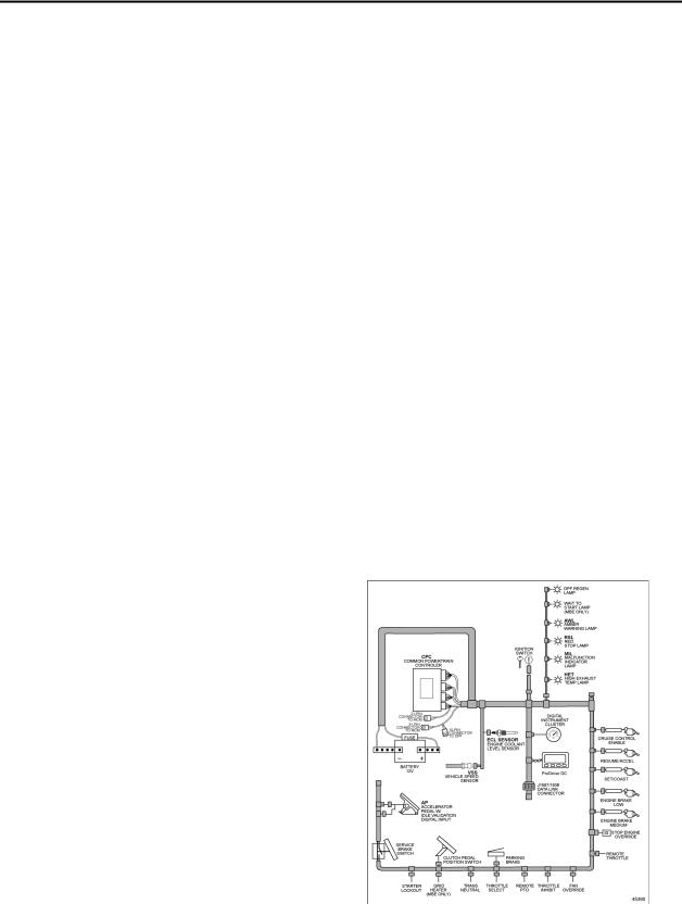
2.2 HARNESSES
There are two major harnesses: the Engine Harness (EH) and the Vehicle Interface Harness (VIH). The Engine Harness is installed at the Detroit Diesel factory and is delivered connected to all engine sensors, the fuel injection system, and the MCM.
The OEM supplied Vehicle Interface Harness connects the CPC to other vehicle systems.
FIGURE 11: VEHICLE INTERFACE HARNESS (GENERAL APPLICATION SHOWN)
 Loading...