


Fault Code 11 and 12 - Accelerator pedal sensor and idling contact
.....Idle pos switch |
= |
Idling contact, accelerator pedal |
|
|
|
Idle pos switch GT..... |
= |
Idling contact accelerator pedal, Geartronic |
|
|
|
Kick-down switch GT..... |
= |
Kick-down contact, Geartronic |
|
|
|
Std..... |
= |
Manual gearbox |
|
|
|
The diagram on the left shows the normal voltage rangeand the correct engagement position for the idling contact in a vehicle witha manual gearbox.
1
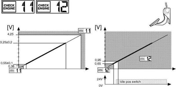
When the accelerator pedal is in the idling position,the voltage from the accelerator pedal sensor must not exceed 0.65 volt, sothat the conditions for engine braking are met. Even at 0.66 volt there isa risk that the engine is not engaged.
The diagram on the right showsthe normal voltage range and the correct engagement position for the idlingcontact on a vehicle equipped with a Geartronic gearbox. Vehicles withGeartronic gearboxes also have two extra contacts, an idling contact and akick-down contact.
Comments on fault code 11, Accelerator pedal sensor
Note that the accelerator pedal controls other functionsthat may stop functioning even although the accelerator pedal does not producea fault code.
For example, the ATR and VEB functions, as well as the regulatingof the power output regulator are disturbed if the accelerator pedal doesnot return to its proper idling position. The ATR and VEB functions can thusnot work and the power output regulation can become unstable around idlingspeed.
When the accelerator pedal does not return to its idling position,the control unit regards this that the acceleration and engine are controlledvia the accelerator pedal diagram.
.....Idle pos switch |
= |
Idling contact, acceleratorpedal |
|
|
|
2
The diagram of the left shows the voltage levels that produce fault code 11.
The fault code is produced for both too high and too low a voltage.
The diagram on the right shows the size of the window within whichthe idling contact will normally be activated.
If the contact is activatedin the low range or not activated in the high range fault code 12 will be produced.
If the fault code has been set, the controlunit will not carry out the component check unless the engine is re-started.
.....OK |
= |
Correct |
.....Idle |
= |
Idling |
.....Limp home |
= |
Emergency regulation |
|
|
|
|
|
|
|
|
|
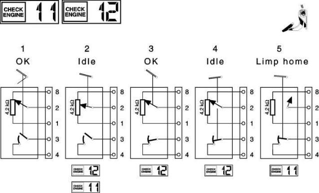
Diagrams 1-5 show some possible situations and what fault codes that areset.
3
Diagram 1.
The accelerator pedal and the idling contact functionfaultlessly.
No fault code is set since the prerequisites have been metand the engine runs normally both when idling and when using the accelerator.
Diagram 2.
The diagram shows the situation when the idlingswitch is always open and indicates the idling position independently of theaccelerator pedal's position. The accelerator pedal functions properly andgives the correct value.
In this situation, where the idling switch andthe accelerator pedal's sensor gives different, the control unit always selectsthe lowest value. In this case, the control unit selects the informationfrom the idling switch, which means that the engine can only be run at idlingspeed.
Fault code 12 will be set since the idling switch missesits window.
Fault code 11 will also be set, since thecontrol unit can not determine with certainty if the idling switch or theaccelerator pedal's sensor is incorrect.
Diagram 3.
The diagram shows the situationwhere the idling switch is always closed. The engine runs normally, but thefault code 12 will be set since the idling switch misses its window.
Diagram 4.
This is the situation where the accelerator pedal'ssensor has stopped functioning and indicates the idling position independentlyof the pedal's position.
The idling switch gives the correct values, butas with the situation in 2, the control unit will select the lowestvalue, that is the value from the accelerator pedal's sensor.
The enginecan only be run at idling speed and fault code 12 is set, sincethe idling switch is closed below its window.
Diagram 5.
In this case, the accelerator pedal's sensor isdamaged but the idling switch gives correct values. The control unit, inthis situation, allows the vehicle to be run using emergency regulation limp home.
By this is meant that when the control unit receives asignal from the idling switch that the accelerator pedal is being presseddown, it produces the same value as for 70% acceleration, until the pedalis completely release to the idling position.
Fault code 11will be set since the outgoing signal from the accelerator pedal's sensorlies outside the permitted value.
4
 Fuel
Fuel
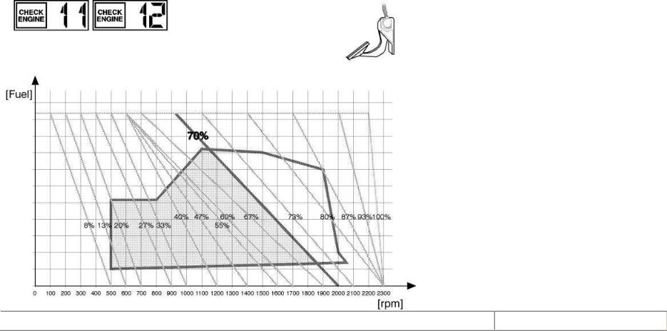
The diagram show the accelerator pedal graph.
The various % valuesshow the electrical output signal from the sensor when the accelerator pedalis pressed down.
The angled lines in the diagram show how the engine reactswhen the load is changed for a particular position of the accelerator pedal.
When the engine's load increases, the engine speed decreases. When theengine speed decreases, the control unit will increase the quantity of fuelso that it follows the angled line that corresponds to the accelerator pedal'soutput signal.
In the diagram, the following limits are set:
5
∙Idling speed (left limit)
∙Max. torque (upper limit)
∙Max. engine speed (right limit)
∙Min. engine speed (lower limit)
When the control unit uses emergency regulation, because the acceleratorpedal is damaged, the same value as for 70% depression of the acceleratorpedal. That is provided that the idling sensor is correct and that the acceleratorpedal is pressed down.
Increasing the acceleration from 0% to 70% takes approximately 1 second.
The reason that 70% has been chosen is to ensure that the max. torque ofthe engine can be obtained.
When the accelerator pedal is released, theacceleration returns to 0%.
Note: Note that with the control unit in the emergency position (70% acceleration),the unloaded engine will reach approx. 1900 rpm when the accelerator pedalis pressed down.
6

 Fuel
Fuel
The diagram shows the accelerator pedal graph forcontrol units from and including part number 8148335.
The control unit was introduced during the Fall of1994.
As can be seen from the diagram, the limit line for max. enginespeed has been moved down to 1600 rpm when the control unit uses emergencyregulation. The previously used 70% line is no longer used, and the controlunit will attempt to give 100%, but will of course be stopped by the new max.engine speed limit.
Fault code 13 - Speed signal
7
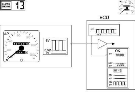
The control unit can control the tachograph's speedsignal in two different ways:
∙Voltage level control
∙Frequency control
Note: Even if the fault code has been set,the control unit will continuously check the speed signal. If the signal returnsto normal, the control unit will use it again.
Voltage level control
The tachograph sends a signal to the control unit.The signal is in the form of a square wave (a pulse train), with a high levelof approx. 8 volts and a low level of approx. 0.5 volts.
When the vehicleis stationary, the signal is either high or low depending on what the sensorposition is on the cog wheel on the transmission's output axle. At rest,the control unit begins to diagnose the voltage levels of the speed signal.
Duringthis diagnosis the control unit can evaluate whether there is a break or shortcircuit to earth or B+. The diagnosis provides two alternatives:
8
Alt. 1. Faultless signal
The signal varies around 8 volts or around 0.5 volts.
Regardingthe form of the signal when measuring using an oscilloscope:
The intendedspeed's normal level; you will see a sample of the feed current ofapprox. 2 milliamps that the control unit injects into the cables.
With a motometer tachograph this will be approx. 1.2 volts. The feed currentis switched on for 400 millisecs every 800 millisecs. This means that asuperimposed square wave will be seen on the tachograph signal.
Alt. 2. Fault code 13
∙The signal's voltage level is 24 volts. Indicates a short circuit toB+.
∙The signal's voltage level is 0 volt. Indicates a short circuit toearth.
∙The signal is identical to the feeder circuit's signal. Indicates anopen circuit.
Frequency check
9
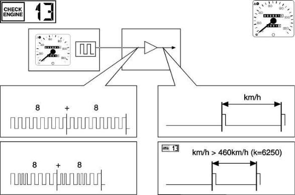
The tachograph's speed signal is first used afterit has been divided by 8, which means a safe filtration of the signal. Ifsignal interference, in the form of one or two voltage spikes shouldoccur, the calculated speed value will not be affected to any great degree.
In order to set fault code 13, the speed must exceed 460km/h with a K factor of 6250, or exceed 230 km/h with a K factor of 12500.
Note: Even if the fault code has been set, the control unit will continuouslycheck the speed signal. If the signal returns to normal, the control unitwill use it again.
Comments to error code 13, Speed signal
Since the speed signal is obtained from the tachograph's buffered output, there could be a fault in the tachograph.
A correctspeedometer is no guarantee that the control unit receives thecorrect input signal.
10
If the speedometer does not give a reading, thecruise control should not function either.
Note: Make sure that the tachographsheets are not inserted wrongly!
Fault code 14 - Feeder relay, control unit
11
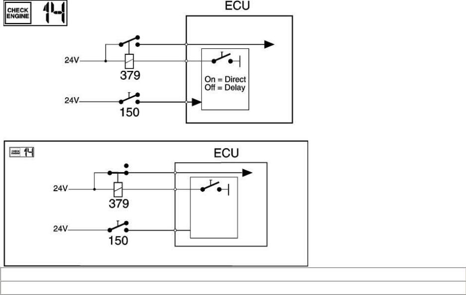
ECU (Electronic Control Unit).....
On = Direct.....
12
 Loading...