


 Loading...
VOLTCRAFT®
User Manual
Voltsoft
Voltsoft User Manual |
Version 2.8 |
|
|
|
|
1 Introduction
Dear Customer,
Welcome to Voltcraft®. Thank you for purchasing this product and we are sure you have made a very good decision.
Voltcraft® - in the field of measuring, charging and network technology, this name represents high quality products which perform superbly and which are created by experts employing continuous innovation and improvement. From ambitious hobby electronics enthusiast to professional user, products from Voltcraft® brand family provide the optimum solution even for the most demanding tasks. Voltcraft® products also offer an almost unbeatable priceperformance ratio. This is why we are absolutely certain: With our Voltcraft® product line, we have created the foundation for a long, prosperous and successful customer partnership.
We wish you have a great deal of enjoyment from your new Voltcraft® product!
2
Voltsoft User Manual |
Version 2.8 |
|||
|
|
|
||
Table of Contents |
|
|||
1 |
Introduction ........................................................................................................ |
2 |
||
2 |
Using this Manual ................................................................................................ |
4 |
||
3 |
Installation .......................................................................................................... |
5 |
||
|
|
3.1 |
System Requirements............................................................................................................ |
5 |
|
|
3.2 |
Install Voltsoft....................................................................................................................... |
6 |
|
|
3.3 |
Migrate existing data............................................................................................................. |
9 |
|
|
3.4 |
Register Voltsoft.................................................................................................................. |
10 |
4 |
Standard Version ............................................................................................... |
12 |
||
|
|
4.1 |
Launch the Voltsoft Windows Client.................................................................................. |
12 |
|
|
4.2 |
General Settings .................................................................................................................. |
13 |
|
|
4.3 |
Add New Device ................................................................................................................. |
15 |
|
|
4.4 |
Export .................................................................................................................................. |
16 |
|
|
4.5 |
Import .................................................................................................................................. |
17 |
|
|
4.6 |
Remove Existing Device..................................................................................................... |
17 |
|
|
4.7 |
Device Control Panel........................................................................................................... |
18 |
5 |
Professional Version .......................................................................................... |
19 |
||
|
|
5.1 |
User Management................................................................................................................ |
19 |
|
|
5.2 |
Email Management.............................................................................................................. |
19 |
|
|
5.3 |
Email Template ................................................................................................................... |
20 |
|
|
5.4 |
Email Alert .......................................................................................................................... |
21 |
|
|
5.5 |
Custom Graph...................................................................................................................... |
22 |
6 |
Supported Devices ............................................................................................. |
24 |
||
|
|
6.1 |
DL101T ............................................................................................................................... |
25 |
|
|
6.2 |
DL121TH ............................................................................................................................ |
31 |
|
|
6.3 |
DL131G............................................................................................................................... |
37 |
|
|
6.4 |
DL141TH ............................................................................................................................ |
45 |
|
|
6.5 |
DL161S ............................................................................................................................... |
51 |
|
|
6.6 |
DL141TH2K ....................................................................................................................... |
58 |
|
|
6.7 |
DL181THP .......................................................................................................................... |
64 |
|
|
6.8 |
DL131LUX ......................................................................................................................... |
70 |
|
|
6.9 |
DL161SAN.......................................................................................................................... |
76 |
|
|
6.10 |
DL201THM ..................................................................................................................... |
82 |
|
|
6.11 |
DL200T / DL210TH / DL220THP.................................................................................. |
88 |
|
|
6.12 |
DL230L / DL240K .......................................................................................................... |
96 |
|
|
6.13 |
DL111K ......................................................................................................................... |
104 |
|
|
6.14 |
DL191A ......................................................................................................................... |
110 |
|
|
6.15 |
DL191V ......................................................................................................................... |
116 |
|
|
6.16 |
DL151AN ...................................................................................................................... |
122 |
|
|
6.17 |
PL-125-T2 / PL-125-T4................................................................................................. |
128 |
|
|
6.18 |
IR 1200-50D / IR 1201-50D.......................................................................................... |
134 |
|
|
6.19 |
SL451............................................................................................................................. |
142 |
|
|
6.20 |
VC930 / VC950 ............................................................................................................. |
149 |
|
|
6.21 |
VC880 / VC650BT........................................................................................................ |
156 |
|
|
6.22 |
VC890............................................................................................................................ |
164 |
|
|
6.23 |
EL4000 .......................................................................................................................... |
173 |
7 |
Auto Upgrade................................................................................................... |
180 |
||
8 |
Appendix.......................................................................................................... |
181 |
||
|
|
8.1 |
Real-Time device list......................................................................................................... |
181 |
3
Voltsoft User Manual |
Version 2.8 |
|
|
|
|
2 Using this Manual
The Voltsoft System (Voltsoft) is integrated control software for controlling different Voltcraft® electronic products. By using Voltsoft, you can manage your Voltcraft® products using only a single piece of software.
This manual will explain the usage and workflow of different components of Voltsoft, and also discuss how Voltsoft can control different hardware models.
There are many terms and abbreviations in this manual that may be unfamiliar to you if you are new to web hosting. You can find information on these terms and abbreviations in the glossary of this manual or by searching them using an Internet search engine such as Google.
4
Voltsoft User Manual |
Version 2.8 |
|
|
|
|
3 Installation
3.1System Requirements
To install Voltsoft, your computer should contain:
-Pentium 233-megahertz (MHz) processor or faster
-At least 1GB of RAM
-At least 2GB of available space on the hard disk
-USB 2.0 / 3.0 Port(s)
Voltsoft only supports the following operating systems:
-Microsoft Windows Vista Service Pack 2 or above
-Microsoft Windows 7
-Microsoft Windows 8
-Microsoft Windows 10
If your Windows does not contain the corresponding service pack version, please perform a Windows update first.
.NET framework library version: - .NET framework 2.0 SP2
If your Windows does not contain the corresponding .NET framework, Voltsoft setup will help you to download it from the Internet. However, it is recommended upgrading first before installation.
Some device may not work if connecting via USB Hubs, included: - DL101T / DL121TH / DL161S / DL180THP / DL111K
5
Voltsoft User Manual |
Version 2.8 |
|
|
|
|
3.2Install Voltsoft
1.Insert the installation CD-ROM in your drive.
2.The menu will be opened automatically (if installation doesn’t start, double-click autorun.exe in your CD-ROM directory). Follow the on-screen instructions.
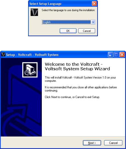
Step 1: Select the installation language
Step 2: Click “Next” for all the following steps
6

Voltsoft User Manual |
Version 2.8 |
|
|
|
|
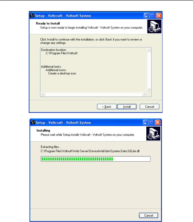
Step 3: Select Destination Location |
|
|
Step 4: Tick the checkbox to create desktop icon for Voltsoft
7
Voltsoft User Manual |
Version 2.8 |
Step 5: Click “Install”. Installation will begin.
8
Voltsoft User Manual |
Version 2.8 |
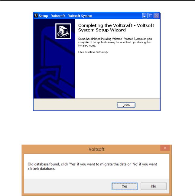
Step 6: Click “Finish” to complete the installation
3.3Migrate existing data
If you have an old version of Voltsoft installed, following dialog will be prompt. Click “Yes” if you want to keep existing data or “No” if you want to have an empty database.
9
Voltsoft User Manual |
Version 2.8 |
|
|
|
|
3.4Register Voltsoft
Voltsoft has two different versions: Standard and Professional. The professional version contains more features than the standard edition.
Standard vs. Professional |
|
|
|
Standard |
Professional |
User Management |
|
√ |
Email Management |
|
√ |
General Settings |
√ |
√ |
Language Preference |
√ |
√ |
Email Template |
|
√ |
Device Management (Add / Remove) |
√ |
√ |
Custom Graph |
|
√ |
Email Alert |
|
√ |
Voltsoft will be installed by default as the standard version. In order to enable the professional features, you have to purchase a software package (VoltSoft Data Logger, BN: 101333) and enter a valid license key (which is attached on CD) to register.
To register:
1.Launch the Voltsoft Windows client
10
Voltsoft User Manual |
Version 2.8 |
2.Click Help -> Online Activation
3.Enter a valid license key and the registration information.
4.Enter the proxy server settings if your computer accesses the Internet through a proxy server.
5.Please read and accept our privacy policy and license agreement.
6.Click the “Activate” button to perform online activation.
7.If activation is successful the following message will be displayed:
If there is any problem during online activation, user can activate via offline activation.
1.Click the Offline Activation button and select the location for saving the activation file (Voltsoft.config)
2.Send the Voltsoft.config to our customer service, email kundenservice@conrad.de
3.Our customer service will return the license file (dms.config) to you.
4.Copy it to the install directory (e.g. C:\Program Files (x86)\Voltsoft)
5.Start Voltsoft again.
11
Voltsoft User Manual |
Version 2.8 |
|
|
|
|
4 Standard Version
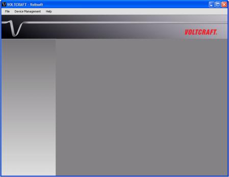
4.1Launch the Voltsoft Windows Client
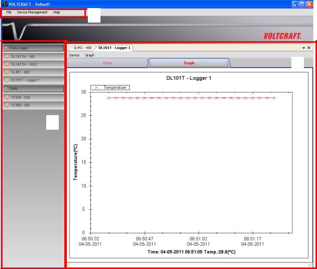
To start the application, please go to Start Menu -> All Programs -> Voltcraft -> Voltsoft Client Main screen of the Voltsoft client is as follows:
1
3
2
1 |
Main Menu Area |
Users can access different functions through the main |
|
|
|
menu. |
|
2 |
Device List Area |
Contains the list of devices which are already registered in |
|
|
|
the system. |
|
|
|
Green icon – Indicates that the device is currently |
|
|
|
connected to the computer |
|
|
|
Red icon - |
Indicates that the device is currently not |
|
|
available. |
|
|
|
Clicking on the icon can open that device in the device |
|
|
|
control panel area. |
|
3 |
Device Control Panel |
The opened device will be displayed in this area. |
|
12

Voltsoft User Manual |
Version 2.8 |
|
|
|
|
4.2General Settings
To launch this module, please click File->Settings.
1
2
3
4
5
|
|
|
|
|
|
|
|
|
6 |
|
|
|
|
|
|
|
|
|
|
|
|
|
|
|
|
|
|
|
|
|
|
|
|
|
1 |
Unit Preference |
|
|
|
Select the measurement unit used in Voltsoft. |
|
2 |
Data Storage |
|
|
|
In order to prevent data overload, the system will delete |
|
|
|
|
|
|
old data automatically. User can specify the number of days |
|
|
|
|
|
|
to keep the device readings. |
|
3 |
Download Data |
|
|
|
If this option was checked and the system is downloading |
|
|
|
|
|
|
new data with measurement time, which already existed in |
|
|
|
|
|
|
the database, then existing data will be overwritten. |
|
4 |
Email Settings |
|
|
|
This area configures the outgoing email settings. |
|
|
|
|
|
|
Email Sender – This will be the email sender of the alert |
|
|
|
|
|
|
email. |
|
|
|
|
|
|
SMTP Server and Port – The outgoing SMTP server name |
|
|
|
|
|
|
and port number. (for Gmail, port number is 465) |
|
|
|
|
|
|
Login ID and Password – The SMTP server login and |
|
|
|
|
|
|
password (if required). |
|
|
|
|
|
|
Enable SSL – Check this checkbox if your SMTP server |
|
|
|
|
|
|
requires SSL encryption (i.e. Gmail) |
|
13
Voltsoft User Manual |
Version 2.8 |
|||
|
|
|
|
|
|
|
|
|
|
|
|
|
This setting is available in the professional version only. |
|
5 |
Web Server Setting |
This option are no longer in use. |
|
|
6 |
Restart Voltsoft |
Restart the Voltsoft Server. |
|
|
|
|
Server |
|
|
|
|
Save |
Save and quit this module. |
|
|
|
Close |
Quit this module without saving. |
|
14
Voltsoft User Manual |
Version 2.8 |
|
|
|
|
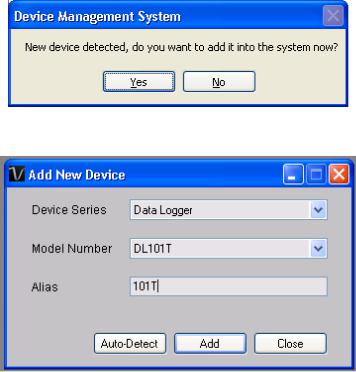
4.3Add New Device
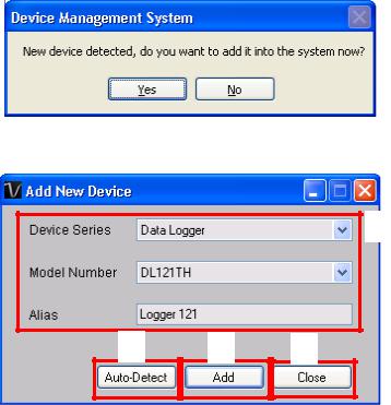
This module should automatically pop up when the user plugs a new device into the computer.
However, to launch this module manually, click Device Management->Add New Device.
1
2 |
3 |
4 |
1 |
Select Device |
To add a new device: |
|
|
|
1. |
Select the device series (only Data Logger available in |
|
|
the current version). |
|
|
|
2. |
Select model number. |
|
|
3. |
Enter a unique alias. |
2 |
Auto-detect |
Click this button to let the system detect if there is any |
|
|
|
device connected but not yet registered. |
|
3 |
Add |
Click the Add button to confirm the addition. |
|
4 |
Close |
Click the Close button to close this module. |
|
15

Voltsoft User Manual |
Version 2.8 |
|
|
|
|
4.4Export
This module allows the user to export device setting and readings.
Click Data > Export to launch this module.
Select the device want to export, then click the “Export” button.
Select the location for export file, then click “Save”.
16
Voltsoft User Manual |
Version 2.8 |
|
|
|
|
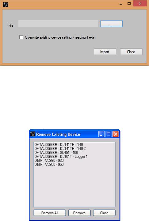
4.5Import
This module allows the user to import device setting and readings.
Click Data > Import to launch this module.
To import device setting / readings, user need to browse the export file (The .vsf generated by the export module), then click the import button.
If the device already exist in voltsoft and you want to overwrite the setting / readings, please check the “Overwrite existing device setting reading if exist” option.
4.6Remove Existing Device
This module allows the user to remove devices which are no longer in use. To launch this module, click Device Management->Remove Existing Device.
To remove a device, click the device in the list and click the “Remove” button. Click “Remove All” button to remove all devices at the same time.
17
Voltsoft User Manual |
Version 2.8 |
|
|
|
|
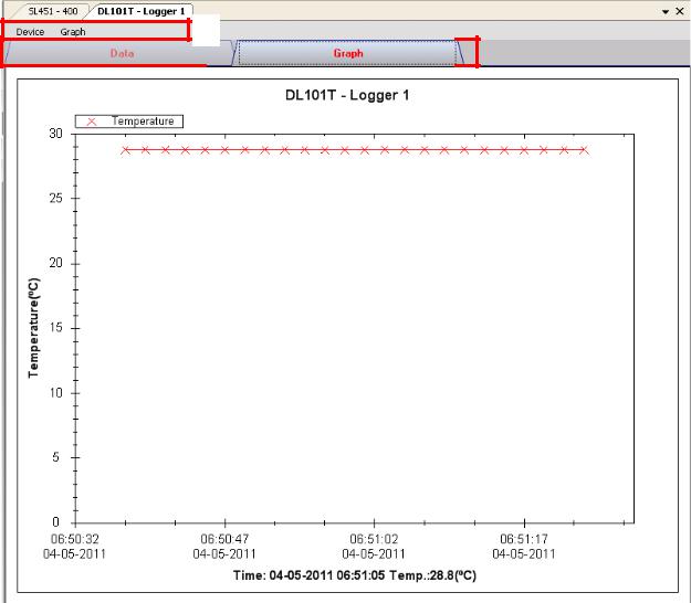
4.7Device Control Panel
The opened device will be displayed in the device control panel area in tab format. Each tab will contain information for one single device.
1
|
|
|
|
|
|
|
2 |
|
|
|
3 |
|
|
|
|
|
|
|
|
|
|
|
|
Each device tab contains: |
|
|
1 |
Device Menu Area |
Each device will contain its own menu, which will be |
|
|
explained in an upcoming section. |
2 |
Data Tab |
Display the selected data in list form. |
3 |
Graph Tab |
Display the selected data in a graphical format. |
The function of the modules may be different for different devices, therefore, they will be discussed in individual device section.
18
Voltsoft User Manual |
Version 2.8 |
|
|
|
|
5 Professional Version
All features of the standard version and some advanced features are included in the professional version. The following features will be available after online activation of the professional version.
5.1User Management
This feature no longer valid.
5.2
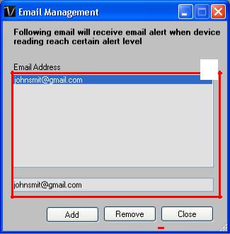
5.2Email Management
This module allows the user to manage the email addresses of those who will receive email alerts. To launch this module, click File->Email Management in the main menu.
1
|
|
|
|
|
|
|
|
|
|
|
|
|
|
|
|
2 |
|
|
|
|
3 |
|
|
4 |
|
||
|
|
|
|
|
|
|
|
|
|
|
|
|
|
|
|
|
|
|
|
|
|
|
|
|
|
|
|
|
|
|
|
|
|
|
|
|
|
|
|
|
|
|
|
|
|
|
|
|
|
|
|
|
|
|
|
1 |
Email Address |
|
The email address is configured within Voltsoft. |
||||||||||
2 |
Add New Email |
|
Input a new email address and click the Add button to add |
||||||||||
|
|
|
|
a new email into the system. |
|
|
|
||||||
3 |
Remove Email |
|
Click on an email in the email address list and click the |
||||||||||
|
|
|
|
Remove button to remove the email from the system. |
|||||||||
4 |
Close |
|
Close this module. |
|
|
|
|||||||
19
Voltsoft User Manual |
Version 2.8 |
|
|
|
|
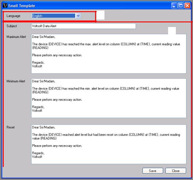
5.3Email Template
To launch this module, click Preference->Email Template.
1
2
|
|
|
|
|
|
|
|
|
|
|
3 |
|
|
|
|
|
|
|
|
|
|
|
|
|
|
|
|
|
|
|
|
1 |
|
Language |
Select the language of the email template. |
|
|||
2 |
|
Message Content |
Fill in the title and content for the email template which will |
|
|||
|
|
|
be sent in the different cases: |
|
|||
|
|
|
Case 1: Maximum Alert |
|
|||
|
|
|
This email will be sent when a reading is higher than the |
|
|||
|
|
|
maximum alarm level. |
|
|||
|
|
|
Case 2: Minimum Alert |
|
|||
|
|
|
This email will be sent when a reading is lower than the |
|
|||
|
|
|
minimum alarm level. |
|
|||
|
|
|
Case 3: Reset Level |
|
|||
|
|
|
This email will be sent when a reading was previously at a |
|
|||
|
|
|
max/min alarm level but has returned to a normal level. |
|
|||
|
|
|
|
|
|
|
|
3 |
|
Save |
Click the Save button to save the template. |
|
|||
4 |
|
Close |
Click the Close button to close the module. |
|
|||
20
Voltsoft User Manual |
Version 2.8 |
|
|
|
|
Variable
The following labels are defined as variables and will be replaced when sending out.
1 |
{DEVICE} |
The device alias |
2 |
{COLUMN} |
The device reading name |
3 |
{READING} |
The device reading value |
4 |
{TIME} |
The time the event happened |
5.4Email Alert
Voltsoft has an email alert feature, which will send out an email to the specified user when the device reading is above or below a certain level.
The user can use this module to select who will receive the email for the specific device.
21
Voltsoft User Manual |
Version 2.8 |
|
|
|
|
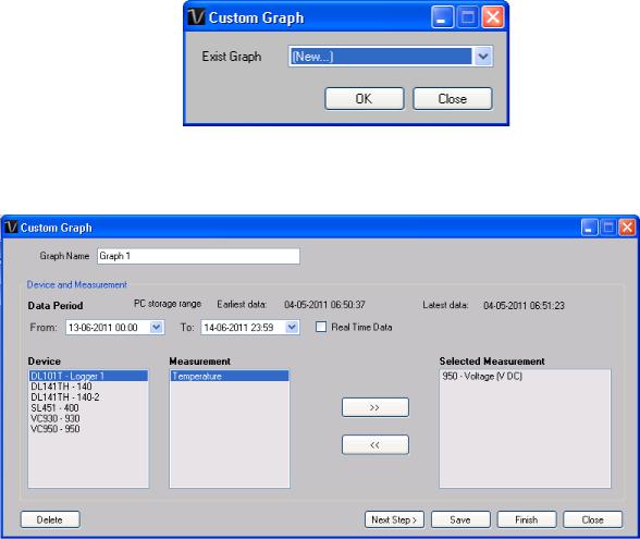
5.5Custom Graph
Custom Graph allows the user to graph the measurement readings from more than one device. To create a custom graph:
1. Select Device Management->Custom Graph in main menu.
2.Select New to create a new graph or select the previous saved graph. Click OK to continue.
3.The Custom Graph detailed interface will be displayed:
22

Voltsoft User Manual Version 2.8
4. Then the user needs to:
I. Select the data period or real-time data (only specific devices support real-time reading).
II. Select the device and measurement column. III. Click Next Step> to continue.
IV. For each column, the system will show the data maximum and minimum values for the selected period.
V.For each column, the user can specify whether it is drawn in Y1 or Y2, specify the Y-axis maximum and minimum values, the corresponding colour of the line or align the Zero level to the same level or not.
VI. Click Finish to generate the graph.
23

Voltsoft User Manual |
Version 2.8 |
|
|
|
|
6 Supported Devices
Voltsoft currently support following devise:
Type |
Device Name |
Data Logger |
DL101T |
Data Logger |
DL111K |
Data Logger |
DL121TH |
Data Logger |
DL131G |
Data Logger |
DL141TH |
Data Logger |
DL141TH2K |
Data Logger |
DL151AN |
Data Logger |
DL161S |
Data Logger |
DL181THP |
Data Logger |
DL191A |
Data Logger |
DL191V |
Data Logger |
DL201THM |
Data Logger |
DL200T |
Data Logger |
DL210TH |
Data Logger |
DL220THP |
Data Logger |
IR 1200-50D |
Data Logger |
PL-125-T2USB / PL-125-T4USB |
Data Logger |
SL451 |
DMM |
VC930 / VC950 |
DMM |
VC880 / VC650BT |
DMM |
VC890 |
EL4000 |
EL4000 |
24
Voltsoft User Manual |
Version 2.8 |
|
|
|
|
6.1DL101T
DL101T is a data logger for storing temperature reading.
6.1.1 Add new DL101T
When Voltsoft detects a new DL101T attached, the following dialog will be popped up:
Click “Yes”, the following dialog will be displayed:
Enter a unique alias for this device, click “Add” will add the device into Voltsoft. User may also launch this module by select Device Management->Add New Device in menu.
6.1.2 Remove DL101T
To remove DL101T, go to Device Management -> Remove Existing Device and its PC data Storage, select the device you want to remove and click the “Remove” button.
25
Voltsoft User Manual |
Version 2.8 |
6.1.3 DL101T – Device Control Panel
The DL101T Device Control Panel contains follow items in menu:
1 |
Device -> Settings |
This will launch the setting page of DL101T. |
2 |
Device -> Download Data |
Download reading from device. |
3 |
Device -> Display / Plot Data |
Select the time range that the device reading |
|
|
should be retrieved. |
4 |
Graph -> Plot Colour |
This will launch the Plot Colour module to change |
|
|
the colour of the individual lines. |
5 |
Graph -> Background Colour |
Change the background colour of the graph to |
|
|
either black or white. |
6 |
Graph -> Grid |
Control whether to show / hide the grid on the |
|
|
graph area. |
7 |
Graph -> Line |
Control whether to show / hide the line on the |
|
|
graph area. |
8 |
Graph -> Points Indicator |
Control whether to show / hide the points |
|
|
indicator. |
9 |
Graph -> Print |
Prints the generated chart. |
10 |
Graph -> Save Image As |
Save the image in the chosen file format. |
11 |
Graph -> Zoom Out |
Zoom out one level. |
12 |
Graph -> Zoom To Fit |
Undo all zoom in and out. |
26
Voltsoft User Manual |
Version 2.8 |
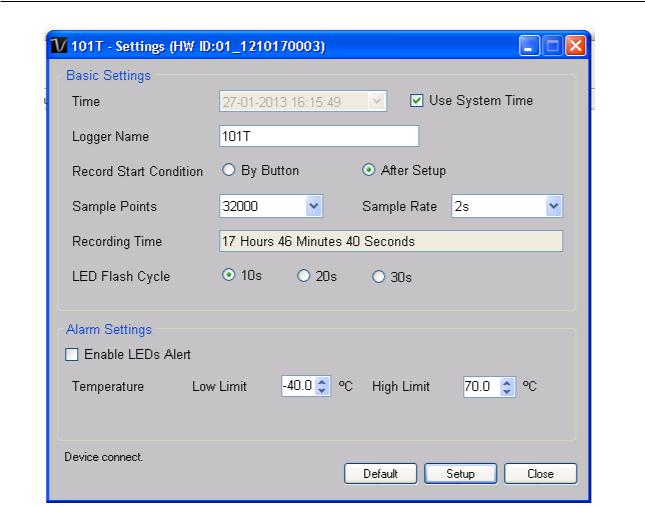
6.1.4 DL101T - Settings
1 |
Time |
Configure the device data time value. |
|
|
The user can specify a defined time or use the system |
|
|
date time. |
2 |
Logger Name |
Input the unique alias for that device. |
3 |
Record Start Condition |
By Button – The data logger will start recording only |
|
|
after the user pressed the red button on the device. |
|
|
After Setup – The data logger will start recording |
|
|
immediately after setup. |
4 |
Sample Points |
Instruct the logger to take a finite number of readings. |
5 |
Sample Rate |
Instruct the logger to log readings at a specific rate. |
6 |
Recording Time |
Calculate the recording time based on the selected |
|
|
sample points and sample rate. |
7 |
LED Flash Cycle |
Configure the LED flash cycle - the longer the time, the |
|
|
longer the battery life. |
8 |
Enable LED Alert |
Enable / disable LED flash when the alarm is triggered. |
9 |
Temperature Low / High |
Configure the temperature low / high alarm level. |
|
Alarm |
|
10 |
Default Button |
Reload the factory default settings. |
11 |
Setup Button |
Save changes. |
12 |
Close Button |
Close this interface. |
Note: Any stored data will be permanently erased when setup is finished.
27

Voltsoft User Manual |
Version 2.8 |
|
|
|
|
6.1.5 DL101T - Download Data
This module allows user to download the data from DL101T.
Click “OK” button to stop the recording and start downloading.
6.1.6 DL101T – Display / Plot Data
This module allows user to select a range for the device readings from the device and display them in the data tab and graph tab.
1 |
PC Storage Range |
Download all data stored in the database. |
2 |
Time Range |
Select the data reading range. |
3 |
OK |
Click OK to accept the input and display the selected |
|
|
reading in the data and graph tabs. |
4 |
Cancel |
Close this module. |
The loading time will increase when more data is retrieved; therefore, the system will be limited to return the first 100,000 records which meet your selection criteria.
28
Voltsoft User Manual |
Version 2.8 |
|
|
|
|
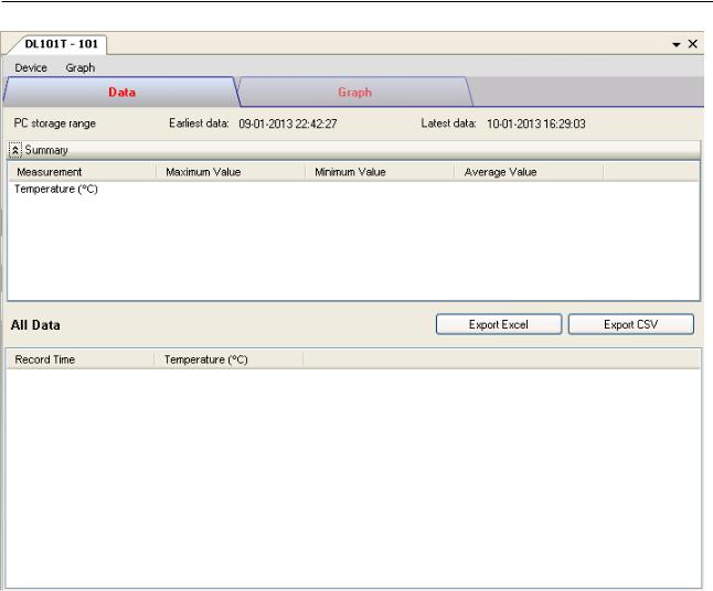
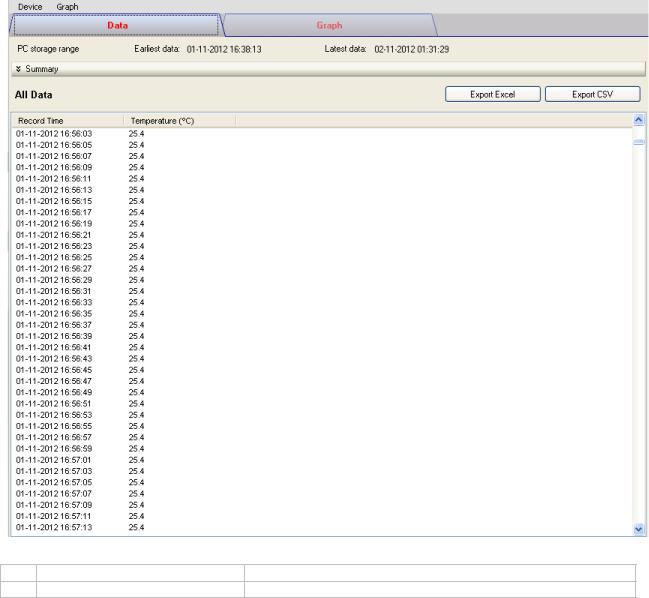
6.1.7 DL101T – Data View
DL101T contains one measurement (Temperature) only, its unit can be Celsius or Fahrenheit, depending on the setting in general setting.
1 |
Export Excel |
Export the reading to Excel (.xls) format. |
2 |
Export CSV |
Export the reading to Excel (.csv) format. |
29
Voltsoft User Manual |
Version 2.8 |
|
|
|
|
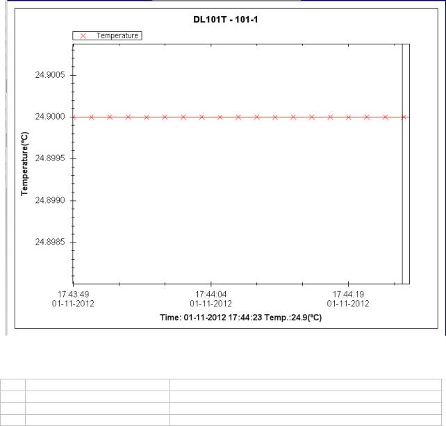
6.1.8 DL101T – Graph View
Our graph support following operations
1 |
Mouse wheel |
Zoom-in / Zoom-Out |
2 |
Mouse click and drag |
Zoom-in |
3 |
Shift + mouse click |
Pan |
4 |
Mouse over on point |
Display reading values |
30
Loading...