


 Loading...
AIR CONDITIONER (SPLIT TYPE)
Installation manual
Outdoor Unit
Model name:
RAV-SM1603AT-E
RAV-SM1603ATZ-E
RAV-SM1603ATZG-E
Not accessible to the general public Vente interdite au grand public Kein öffentlicher Zugang Non accessibile a clienti generici
No destinado al público en general Não acessível ao público em geral Niet geschikt voor huishoudelijk gebruik
Μη προσβάσιμο από το γενικό κοινό
Недоступен для посторонних
Genel erişime açık değildir
Installation manual |
|
English |
Air conditioner (Split type) |
1 |
|
|
|
|
Manuel d'installation |
|
|
|
Français |
|
Climatiseur (Type split) |
25 |
|
|
|
|
Installations-handbuch |
|
|
|
Deutsch |
|
Klimagerät (Split-typ) |
49 |
|
|
|
|
Manuale di installazione |
|
|
|
Italiano |
|
Condizionatore d’aria (Tipo split) |
73 |
|
|
|
|
Manual de instalación |
|
|
|
Español |
|
Aire acondicionado (Tipo split) |
97 |
|
|
|
|
Manual de Instalação |
|
|
|
Português |
|
Ar condicionado (Tipo split) |
121 |
|
|
|
|
Installatiehandleiding |
|
|
|
Nederlands |
|
Airconditioner (Gesplitst type) |
145 |
|
|
|
|
Εγχειρίδιο εγκατάστασης |
|
|
|
Ελληνικά |
|
Κλιματιστικό(Τύπου Split) |
169 |
|
|
|
|
Руководство по установке |
|
|
|
|
|
Кондиционер воздуха |
193 |
Русский |
(сплит-система) |
||
Montaj Kılavuzu |
|
|
|
Türkçe |
|
Klima (Split tip) |
217 |
|
|
|
|
Digital Inverter |
Outdoor Unit Installation Manual |
Please read this Installation Manual carefully before installing the Air Conditioner.
•This Manual describes the installation method of the outdoor unit.
•For installation of the indoor unit, follow the Installation Manual attached to the indoor unit.
ADOPTION OF NEW REFRIGERANT
This Air Conditioner is a new type which adopts a new refrigerant HFC (R410A) instead of the conventional refrigerant R22 in order to prevent destruction of the ozone layer.
Contents |
|
|
1 |
ACCESSORY PARTS AND REFRIGERANT . . . . . . . . . . . . . . . . . . . . . . . . . . . . . . . |
. 2 |
2 |
PRECAUTIONS FOR SAFETY . . . . . . . . . . . . . . . . . . . . . . . . . . . . . . . . . . . . . . . . . . |
. 3 |
3 |
INSTALLATION OF NEW REFRIGERANT AIR CONDITIONER . . . . . . . . . . . . . . . . |
. 4 |
4 |
SELECTION OF INSTALLATION . . . . . . . . . . . . . . . . . . . . . . . . . . . . . . . . . . . . . . . . |
. 6 |
5 |
REFRIGERANT PIPING . . . . . . . . . . . . . . . . . . . . . . . . . . . . . . . . . . . . . . . . . . . . . . . . |
11 |
6 |
AIR PURGING . . . . . . . . . . . . . . . . . . . . . . . . . . . . . . . . . . . . . . . . . . . . . . . . . . . . . . . |
14 |
7 |
ELECTRICAL WORK . . . . . . . . . . . . . . . . . . . . . . . . . . . . . . . . . . . . . . . . . . . . . . . . . . |
16 |
8 |
EARTHING . . . . . . . . . . . . . . . . . . . . . . . . . . . . . . . . . . . . . . . . . . . . . . . . . . . . . . . . . . |
20 |
9 |
FINISHING . . . . . . . . . . . . . . . . . . . . . . . . . . . . . . . . . . . . . . . . . . . . . . . . . . . . . . . . . . |
20 |
10 TEST RUN . . . . . . . . . . . . . . . . . . . . . . . . . . . . . . . . . . . . . . . . . . . . . . . . . . . . . . . . . . |
20 |
|
11 ANNUAL MAINTENANCE . . . . . . . . . . . . . . . . . . . . . . . . . . . . . . . . . . . . . . . . . . . . . . |
20 |
|
12 FUNCTIONS TO BE IMPLEMENTED LOCALLY . . . . . . . . . . . . . . . . . . . . . . . . . . . . |
21 |
|
13 TROUBLESHOOTING . . . . . . . . . . . . . . . . . . . . . . . . . . . . . . . . . . . . . . . . . . . . . . . . . |
22 |
|
14 APPENDIX . . . . . . . . . . . . . . . . . . . . . . . . . . . . . . . . . . . . . . . . . . . . . . . . . . . . . . . . . . |
23 |
|
1-EN |
– 1 – |

Digital Inverter |
Outdoor Unit Installation Manual |
1 ACCESSORY PARTS AND REFRIGERANT
Accessory parts
Part name |
Q’ty |
Shape |
Usage |
|
Outdoor unit |
1 |
|
(Hand this directly to the customer.) |
|
Installation manual |
|
|
||
|
|
|
|
|
Drain nipple |
1 |
|
|
|
Waterproof rubber cap |
5 |
|
|
|
Protective bush |
1 |
|
For protecting wires (pipe cover) |
|
Guard material for passage |
1 |
|
For protecting passage part (pipe cover) |
|
part |
|
|
||
|
|
|
|
|
|
|
|
For conforming to EMC standards for twin/triple systems |
EN |
Ferrite core |
1 |
|
Color: White |
|
|
|
|
(Used for indoor/outdoor connecting wires) |
|
|
|
|
For conforming to EMC standards for twin/triple systems |
|
Clamp filter |
1 |
|
Color: Gray |
|
|
|
|
(Used for outdoor fan motor lead wire) |
|
Banding band |
2 |
|
For conforming to EMC standards for twin/triple systems |
|
|
(For clamping the clamp filter and ferrite core) |
|
||
|
|
|
|
Refrigerant Piping
•Piping kit used for the conventional refrigerant cannot be used.
•Use copper pipe with 0.8 mm or more thickness for Ø9.5 mm. Use copper pipe with 1.0 mm or more thickness for Ø15.9 mm.
•Flare nut and flare works are also different from those of the conventional refrigerant. Take out the flare nut attached to the air conditioner, and use it.
– 2 – |
2-EN |

Digital Inverter |
Outdoor Unit Installation Manual |
2 PRECAUTIONS FOR SAFETY
•Ensure that all Local, National and International regulations are satisfied.
•Read this “PRECAUTIONS FOR SAFETY” carefully before Installation.
•The precautions described below include the important items regarding safety. Observe them without fail.
•After the installation work, perform a trial operation to check for any problem.
Follow the Owner’s Manual to explain how to use and maintain the unit to the customer.
•Turn off the main power supply switch (or breaker) before the unit maintenance.
•Ask the customer to keep the Installation Manual together with the Owner’s Manual.
 WARNING
•Ask an authorized dealer or qualified installation professional to install/maintain the air conditioner.
Inappropriate installation may result in water leakage, electric shock or fire.
•Be sure to connect earth wire. (grounding work)
Incomplete grounding cause an electric shock.
Do not connect ground wires to gas pipes, water pipes, lightning rods or ground wires for telephone wires.
•Turn off the main power supply switch or breaker before attempting any electrical work.
Make sure all power switches are off. Failure to do so may cause electric shock. Use an exclusive power circuit for the air conditioner. Use the rated voltage.
•Connect the connecting wire correctly.
If the connecting wire is connected in a wrong way, electric parts may be damaged.
•When moving the air conditioner for the installation into another place, be very careful not to enter any gaseous matter other than the specified refrigerant into the refrigeration cycle.
If air or any other gas is mixed in the refrigerant, the gas pressure in the refrigeration cycle becomes abnormally high and it may resultingly causes pipe burst and injuries on persons.
•Do not modify this unit by removing any of the safety guards or by by-passing any of the safety interlock switches.
•After unpacking the unit, examine it carefully if there are possible damage.
•Do not install in a place that might increase the vibration of the unit.
•To avoid personal injury (with sharp edges), be careful when handling parts.
•Perform installation work properly according to the Installation Manual.
Inappropriate installation may result in water leakage, electric shock or fire.
•When the air conditioner indoor unit is installed in a small room, provide appropriate measures to ensure that the concentration of refrigerant leakage occur in the room does not exceed the critical level.
•Tighten the flare nut with a torque wrench in the specified manner.
Excessive tightening of the flare nut may cause a crack in the flare nut after a long period, which may result in refrigerant leakage.
•Wear heavy gloves during the installation work to avoid injury.
•Install the air conditioner securely in a location where the base can sustain the weight adequately.
•Perform the specified installation work to guard against an earthquake.
If the air conditioner is not installed appropriately, accidents may occur due to the falling unit.
•If refrigerant gas has leaked during the installation work, ventilate the room immediately.
If the leaked refrigerant gas comes in contact with fire, noxious gas may generate.
•After the installation work, confirm that refrigerant gas does not leak.
If refrigerant gas leaks into the room and flows near a fire source, such as a cooking range, noxious gas might generate.
•Electrical work must be performed by a qualified electrician in accordance with the Installation Manual. Make sure the air conditioner uses an exclusive power supply.
An insufficient power supply capacity or inappropriate installation may cause fire.
•Use the specified wires for wiring connect the terminals securely fix.
To prevent external forces applied to the terminals from affecting the terminals.
3-EN |
– 3 – |

Digital Inverter |
Outdoor Unit Installation Manual |
 WARNING
•When the air conditioner cannot cool or heat a room well, contact the dealer from whom you purchased the air conditioner as refrigerant leakage is considered as the cause.
In the case of repair that requires refill of refrigerant, ask service personnel about details of the repair.
The refrigerant used in the air conditioner is harmless.
Generally, the refrigerant does not leak. However, if the refrigerant leaks in a room and a heater or stove burner in the room catches fire, it may generate toxic gas.
When you ask service personnel for repairing refrigerant leakage, confirm that the leakage portion has been completely repaired.
•Conform to the regulations of the local electric company when wiring the power supply.
Inappropriate grounding may cause electric shock.
•Do not install the air conditioner in a location subject to a risk of exposure to a combustible gas.
If a combustible gas leaks, and stays around the unit, a fire may occur.
•Install the refrigerant pipe securely during the installation work before operating the air conditioner.
If the compressor is operated with the valve open and without the refrigerant pipe, the compressor sucks air and the refrigeration cycle is overpressurized, which may cause a burst or injury.
•For the refrigerant recovery work (collection of refrigerant from the pipe to the compressor), stop the compressor before disconnecting the refrigerant pipe.
If the refrigerant pipe is disconnected while the compressor is working with the valve open, the compressor sucks air and the refrigeration cycle is overpressurized, which may cause a burst or injury.
CAUTION |
EN |
New Refrigerant Air Conditioner Installation
•THIS AIR CONDITIONER ADOPTS THE NEW HFC REFRIGERANT (R410A) WHICH DOES NOT DESTROY OZONE LAYER.
•The characteristics of R410A refrigerant are ; easy to absorb water, oxidizing membrane or oil, and its pressure is approx. 1.6 times higher than that of refrigerant R22. Accompanied with the new refrigerant, refrigerating oil has also been changed. Therefore, during installation work, be sure that water, dust, former refrigerant, or refrigerating oil does not enter the refrigerating cycle.
•To prevent charging an incorrect refrigerant and refrigerating oil, the sizes of connecting sections of charging port of the main unit and installation tools are changed from those for the conventional refrigerant.
•Accordingly the exclusive tools are required for the new refrigerant (R410A).
•For connecting pipes, use new and clean piping designed for R410A, and please care so that water or dust does not enter.
To Disconnect the Appliance from Main Power Supply
•This appliance must be connected to the main power supply by means of a switch with a contact separation of at least 3 mm.
•The installation fuse 40 A (All type fuse can be used) must be used for the power supply line of this conditioner.
3 INSTALLATION OF NEW REFRIGERANT AIR CONDITIONER
•The R410A refrigerant is more susceptible to impurities such as water, oxide membrane, oils, and fats. With the adoption of the new refrigerant, refrigerating oil has also been changed.
Be careful so that water, dust, conventional refrigerant, and/or conventional refrigerating oil do not enter the refrigerating cycle of the new refrigerant air conditioner.
•To prevent different refrigerant or refrigerating oil being mixed, the sizes of the charging port of the unit and the installation tool connecting sections are different from the conventional refrigerant. Accordingly the following exclusive tools are required for the new refrigerant R410A.
– 4 – |
4-EN |

Digital Inverter |
Outdoor Unit Installation Manual |
Required Tools/Equipment and Precautions for Use
Prepare the tools and equipment listed in the following table before starting installation work. Newly prepared tools and equipment must be used exclusively.
Legend
 : Prepared newly (Use for R410A only. Do not use for refrigerant R22 or R407C etc..)
  : Conventional tools/equipment are available
Tools/equipment |
Use |
How to use tools/equipment |
|
|
|
|
|
Gauge manifold |
Vacuuming/charging |
Prepared newly for R410A only |
|
|
refrigerant and operation |
|
|
Charging hose |
Prepared newly for R410A only |
||
check |
|||
|
|
|
|
Charging cylinder |
Can not be used |
Unusable (Use the refrigerant charging measure |
|
instead.) |
|||
|
|
||
Gas leak detector |
Gas leak check |
Prepared newly |
|
|
|
|
|
Vacuum pump with backflow |
Vacuum drying |
Unusable |
|
prevention function |
|||
|
|
||
Vacuum pump with backflow |
Vacuum drying |
R22 (Conventional tools) |
|
prevention function |
|||
|
|
||
Flare tool |
Flare machining of pipes |
Usable if dimensions are adjusted. |
|
|
|
|
|
Bender |
Bending pipes |
R22 (Conventional tools) |
|
|
|
|
|
Refrigerant recovery equipment |
Refrigerant recovery |
For R410A only |
|
|
|
|
|
Torque wrench |
Tightening flare nuts |
Exclusive for Ø12.7 mm and Ø15.9 mm |
|
|
|
|
|
Pipe cutter |
Cutting pipes |
R22 (Conventional tools) |
|
|
|
|
|
Refrigerant cylinder |
Charging refrigerant |
For R410A only |
|
Discriminated by the refrigerant name on the |
|||
|
|
cylinder. |
|
Welding machine and nitrogen |
Welding pipes |
R22 (Conventional tools) |
|
cylinder |
|||
|
|
||
Refrigerant charging measure |
Charging refrigerant |
R22 (Conventional tools) |
|
|
|
|
Refrigerant Piping
New refrigerant (R410A)
When using the conventional piping kit
•When using the conventional piping kit that has no indication of applicable refrigerant types, be sure to use it with a wall thickness of 0.8 mm for Ø6.4 mm, Ø9.5 mm, and Ø12.7 mm, and with a wall thickness of 1.0 mm for Ø15.9 mm. Never use the conventional piping kit with a wall thickness less than these thicknesses due to insufficient pressure capacity.
When using general copper pipes
•Use general copper pipes with a wall thickness of 0.8 mm for Ø6.4 mm, Ø9.5 mm, and Ø12.7 mm, and with a wall thickness of 1.0 mm for Ø15.9 mm.
Never use any copper pipes with a wall thickness less than these thicknesses.
Flare nuts and flare machining
•The flare nuts and flare machining are different from those for the conventional refrigerant. Use the flare nuts supplied with the air conditioner or those for R410A.
•Before performing flare machining, carefully read “REFRIGERANT PIPING”
5-EN |
– 5 – |

Digital Inverter |
Outdoor Unit Installation Manual |
4 SELECTION OF INSTALLATION
Before installation
Be careful to the following items before installation.
Length of refrigerant pipe
Length of refrigerant
pipe connected to Item indoor/outdoor unit
5 m to 30 m |
Addition of refrigerant is |
|
unnecessary at the local site. |
||
|
||
|
<Addition of refrigerant> |
|
*31 m to 50 m |
Add 40 g of refrigerant for |
|
every 1m of pipe which |
||
|
||
|
exceeds 30 m. |
*Caution at addition of refrigerant
When the total length of refrigerant pipe exceeds 30 m, add 40 g /m of refrigerant and the maximum total length of pipe is 50 m. (Max. amount of additional refrigerant is 800 g.) Charge the refrigerant accurately. Overcharge may cause a serious trouble of compressor.
*Do not connect a refrigerant pipe shorter than
5 m.
This may cause a malfunction of the compressor or other devices.
Airtight test
1.Before starting an airtight test, further tighten the spindle valves on the gas side and liquid side.
2.Pressurize the pipe with nitrogen gas charged from the service port to the design pressure (4.15 Mpa) to conduct the airtight test.
3.After the airtight test is completed, evacuate the nitrogen gas.
Air purge
•For air purge, use a vacuum pump.
•Do not use refrigerant charged in the outdoor unit for air purge. (The refrigerant for air purge is not contained in the outdoor unit.)
Earthing
 WARNING
Make sure that proper earthing is provided.
Improper earthing may cause electric shock. For how to check earthing, contact the dealer who installed the air conditioner or a professional installation company.
•Proper earthing can prevent charging of electricity on the outdoor unit surface due to high frequency of the frequency converter (inverter) in the outdoor unit, as well as prevent electric shock. If the outdoor unit is not properly earthed, you may feel electric shock.
•Be sure to connect earth wire. (grounding work)
Incomplete grounding cause an electric shock. Do not connect ground wires to gas pipes, water
pipes, lightning rods or ground wires for EN telephone wires.
Test Run
Turn on the leakage breaker at least 12 hours before starting a test run to protect the compressor during startup.
 CAUTION
Incorrect work may result in a malfunction or complaints of customers.
Electrical wiring
•Be sure to fix the power wires and indoor/ outdoor connecting wires with clamps so that they do not contact with the cabinet, etc.
– 6 – |
6-EN |
Digital Inverter |
Outdoor Unit Installation Manual |
Installation Place
 WARNING
Install the outdoor unit properly at a place that is durable enough to the weight of the outdoor unit.
Insufficient durability may cause the outdoor unit to fall, which may result in injury.
 CAUTION
Do not install the outdoor unit at a place subject to combustible gas leak.
Accumulation of combustible gas around the outdoor unit may cause a fire.
Install the outdoor unit at a place that meets the following conditions after customer’s consent is obtained.
•A well-ventilated place free from obstacles near the air inlets and air outlet
•A place that is not exposed to rain or direct sunlight
•A place that does not increase the operating noise or vibration of the outdoor unit
•A place that does not cause any drainage problem with discharged water
Do not install the outdoor unit at the following places.
•A place full of saline atmosphere (coastal area) or sulfide gas (hot-spring area)
(Special maintenance is required.)
•A place subject to oil, vapor, oily smoke, or corrosive gas
•A place where organic solvent is used
•A place where high-frequency equipment (including inverter equipment, private power generator, medical equipment, and communication equipment) is used (Installation in this place may cause malfunction of the air conditioner, abnormal control or problems due to noise to such equipment.)
•A place where the discharged air of the outdoor unit blows against the window of the neighboring house
•A place where the operating noise of the outdoor unit is transmitted
•When the outdoor unit is installed in an elevated position, be sure to secure its feet.
•A place where the drain water does not make any problem.
 CAUTION
1.Install the outdoor unit at a place where discharge air is not blocked.
2.When an outdoor unit is installed in a place that is always exposed to a strong wind like a coast or on a high storey of a building, secure a normal fan operation by using a duct or a wind shield.
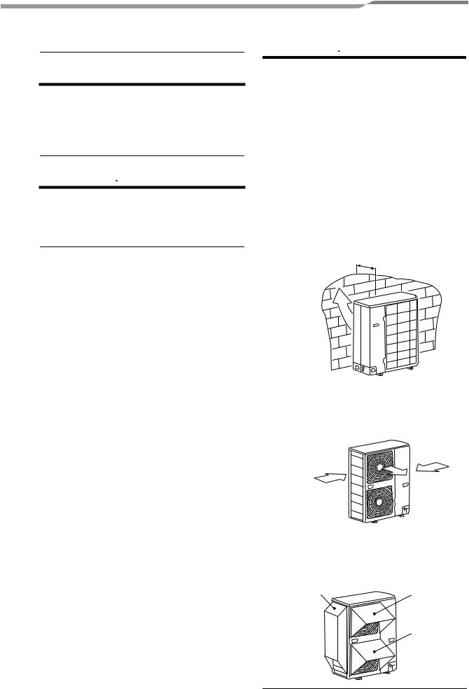
3.When installing the outdoor unit in a place that is constantly exposed to a strong wind such as the upper stairs or rooftop of a building, apply the windproof measures referring to the following examples.
1)Install the unit so that its discharge port faces to the wall of the building.
Keep a distance 500 mm or more between the unit and the wall surface.
500
2)Supposing the wind direction during the operation season of the air conditioner, install the unit so that the discharge port is set at right angle to the wind direction.
Strong Strong wind wind
•When using an air conditioner under low outside temperature condition (Outside temp.:-5 °C or lower) with COOL mode, prepare a duct or wind shield so that it is not affected by the wind.
<Example>
Wind shield |
Wind shield |
Wind shield
7-EN |
– 7 – |
Loading...