


 1402110301
Refrigerant Detection System
Installation Instructions
Détecteur de Réfrigérant
Instructions d’Installation
Kältemitteldetektor
Installationsanleitung
Detector de Refrigerante
Instrucciones de Instalación
Rivelatore del frigorigeno
Istruzioni per l’installazione
Koelmiddeldetector
Installatievoorschriften
RBC-RD1-PE
RBC-RD2-PE
HFCR407C

Contents
It is important to read this manual carefully before starting the installation.
Caution and Components List . . . . . . . . . . . . . . . . . . . . . . . . . . . . . . . . . . . . . . . . . . . . . . . .4 Specifications . . . . . . . . . . . . . . . . . . . . . . . . . . . . . . . . . . . . . . . . . . . . . . . . . . . . . . . . . . . .5 Model Differentiation . . . . . . . . . . . . . . . . . . . . . . . . . . . . . . . . . . . . . . . . . . . . . . . . . . . . . .6 Unit Setup . . . . . . . . . . . . . . . . . . . . . . . . . . . . . . . . . . . . . . . . . . . . . . . . . . . . . . . . . . . .6-7 System Overview . . . . . . . . . . . . . . . . . . . . . . . . . . . . . . . . . . . . . . . . . . . . . . . . . . . . . .8-10 Electrical Wiring – RD1 . . . . . . . . . . . . . . . . . . . . . . . . . . . . . . . . . . . . . . . . . . . . . . . . .11-12 Electrical Wiring – RD2 . . . . . . . . . . . . . . . . . . . . . . . . . . . . . . . . . . . . . . . . . . . . . . . . .13-14
Sommaire
Il est important de lire ce manuel attentivement avant de procéder à l’installation.
Avertissement et Liste des Composants . . . . . . . . . . . . . . . . . . . . . . . . . . . . . . . . . . . . . . . .15 Spécifications . . . . . . . . . . . . . . . . . . . . . . . . . . . . . . . . . . . . . . . . . . . . . . . . . . . . . . . . . . .16 Différenciation des Modèles . . . . . . . . . . . . . . . . . . . . . . . . . . . . . . . . . . . . . . . . . . . . . . . .17 Réglage de l’Unité . . . . . . . . . . . . . . . . . . . . . . . . . . . . . . . . . . . . . . . . . . . . . . . . . . . .17-18 Vue d’ensemble du Système . . . . . . . . . . . . . . . . . . . . . . . . . . . . . . . . . . . . . . . . . . . . .19-21 Câblage Electrique – RD1 . . . . . . . . . . . . . . . . . . . . . . . . . . . . . . . . . . . . . . . . . . . . . . .22-23 Câblage Electrique – RD2 . . . . . . . . . . . . . . . . . . . . . . . . . . . . . . . . . . . . . . . . . . . . . . .24-25
Inhalt
Bitte diese Anleitung vor Beginn der Installation aufmerksam durchlesen.
Warnhinweise und Bauteileliste . . . . . . . . . . . . . . . . . . . . . . . . . . . . . . . . . . . . . . . . . . . . . .26 Technische Daten . . . . . . . . . . . . . . . . . . . . . . . . . . . . . . . . . . . . . . . . . . . . . . . . . . . . . . . .27 Modellunterscheidung . . . . . . . . . . . . . . . . . . . . . . . . . . . . . . . . . . . . . . . . . . . . . . . . . . . .28 Gerätekonfiguration . . . . . . . . . . . . . . . . . . . . . . . . . . . . . . . . . . . . . . . . . . . . . . . . . . .28-29 Systemübersicht . . . . . . . . . . . . . . . . . . . . . . . . . . . . . . . . . . . . . . . . . . . . . . . . . . . . . .30-32 Verdrahtung – RD1 . . . . . . . . . . . . . . . . . . . . . . . . . . . . . . . . . . . . . . . . . . . . . . . . . . . .33-34 Verdrahtung – RD2 . . . . . . . . . . . . . . . . . . . . . . . . . . . . . . . . . . . . . . . . . . . . . . . . . . . .35-36
Contenido |
|
Es importante leer atentamente este manual antes de realizar la instalación. |
|
Aviso y Lista de Componentes . . . . . . . . . . . . . . . . . . . . . . . . . . . . . . . . . . . . . . . . . . . . |
. . .37 |
Especificaciones . . . . . . . . . . . . . . . . . . . . . . . . . . . . . . . . . . . . . . . . . . . . . . . . . . . . . . |
. . .38 |
Diferenciación de Modelos . . . . . . . . . . . . . . . . . . . . . . . . . . . . . . . . . . . . . . . . . . . . . . |
. . .39 |
Configuración de la Unidad . . . . . . . . . . . . . . . . . . . . . . . . . . . . . . . . . . . . . . . . . . . . . . |
39-40 |
Resumen del Sistema . . . . . . . . . . . . . . . . . . . . . . . . . . . . . . . . . . . . . . . . . . . . . . . . . . |
41-43 |
Cableado Eléctrico – RD1 . . . . . . . . . . . . . . . . . . . . . . . . . . . . . . . . . . . . . . . . . . . . . . . |
44-45 |
Cableado Eléctrico – RD2 . . . . . . . . . . . . . . . . . . . . . . . . . . . . . . . . . . . . . . . . . . . . . . . |
46-47 |
Indice |
|
È importante leggere attentamente questo manuale prima di iniziare l’installazione.
Avvertenze ed Elenco dei componenti . . . . . . . . . . . . . . . . . . . . . . . . . . . . . . . . . . . . . . . . .48 Caratteristiche tecniche . . . . . . . . . . . . . . . . . . . . . . . . . . . . . . . . . . . . . . . . . . . . . . . . . . .49 Differenziazione dei modelli . . . . . . . . . . . . . . . . . . . . . . . . . . . . . . . . . . . . . . . . . . . . . . . .50 Predisposizione dell’apparecchio . . . . . . . . . . . . . . . . . . . . . . . . . . . . . . . . . . . . . . . . . .50-51 Panoramica del sistema . . . . . . . . . . . . . . . . . . . . . . . . . . . . . . . . . . . . . . . . . . . . . . . . .52-54 Circuito elettrico – RD1 . . . . . . . . . . . . . . . . . . . . . . . . . . . . . . . . . . . . . . . . . . . . . . . . .55-56 Circuito elettrico – RD2 . . . . . . . . . . . . . . . . . . . . . . . . . . . . . . . . . . . . . . . . . . . . . . . . .57-58
Inhoud
Het is belangrijk om deze handleiding aandachtig te lezen alvorens de installatie aan te vangen.
Waarschuwingsen Onderdelenlijst . . . . . . . . . . . . . . . . . . . . . . . . . . . . . . . . . . . . . . . . . .59 Specificaties . . . . . . . . . . . . . . . . . . . . . . . . . . . . . . . . . . . . . . . . . . . . . . . . . . . . . . . . . . . .60 Modeldifferentiatie . . . . . . . . . . . . . . . . . . . . . . . . . . . . . . . . . . . . . . . . . . . . . . . . . . . . . . .61 Setup van de Installatie . . . . . . . . . . . . . . . . . . . . . . . . . . . . . . . . . . . . . . . . . . . . . . . . .61-62 Systeemoverzicht . . . . . . . . . . . . . . . . . . . . . . . . . . . . . . . . . . . . . . . . . . . . . . . . . . . . .63-65 Elektrische Bedrading – RD1 . . . . . . . . . . . . . . . . . . . . . . . . . . . . . . . . . . . . . . . . . . . . .66-67 Elektrische Bedrading – RD2 . . . . . . . . . . . . . . . . . . . . . . . . . . . . . . . . . . . . . . . . . . . . .68-69
3
GB
F
D
E
I
NL

GB
Caution
This manual contains the installation instructions for the Refrigerant Leak detector units RBC-RD1-PE and RBC-RD2-PE. Please read these instructions thoroughly before starting the installation work.
 This equipment should only be installed by suitably trained operatives.
Incorrect installation by unqualified personnel may result in the refrigerant detector units not operating correctly, electric shock or fire.
In all cases ensure safe working practices are followed. Observe precautions for persons in the vicinity of the works.
 Ensure that all local, national and international regulations are satisfied.
 Before commencing the installation, ensure all relevant electrical supplies are isolated.
Carefully unpack the equipment and check for damage or shortages. Please report any damage or shortages immediately.
If solenoid valves are to be used, ensure they are designed to be used with high/low  temperatures and pressures of the refrigerant and they are capable of bi-directional
flow.
The refrigerant detector units comply with the following EC Directives: 73/23/EEC – Low Voltage Directive
89/336/EEC – Electro Magnetic Compatibility
Accordingly the refrigerant detector units are designated for use in commercial and industrial environments.
|
|
|
Components List |
|
|
Refrigerant Detector Components: |
|
|
|||
RBC-RD1-PE: |
Control box & screw caps |
|
|
||
|
|
|
Remote sensor/audible alarm assembly |
|
|
|
|
|
FCU interface cable |
|
|
|
|
|
Installation instructions |
|
|
|
|
|
Owners manual |
|
|
RBC-RD2-PE: |
Control box with integral sensor & screw caps |
|
|
||
|
|
|
CDU interface cable |
|
|
|
|
|
Installation instructions |
|
|
|
|
|
Owners manual |
|
|
Mounting bracket
Screws x 4
4

GB
Specifications
Model |
|
RBC-RD1-PE |
RBC-RD2-PE |
|
|
|
|
|
|
Description |
|
Indoor refrigerant detector |
Outdoor refrigerant detector |
|
Remote Sensor & Sounder |
Standard |
N/A |
||
Power |
Phase |
Single |
Single |
|
Volts |
220 - 240 |
220 - 240 |
||
Supply |
||||
Hz |
50 |
50 |
||
|
||||
|
mA |
300 |
300 |
|
Refrigerant Type |
|
HFC 407C |
HFC 407C |
|
Colour |
|
Grey |
Grey |
|
Height (inc glands) |
mm |
80 (102) |
80 (102) |
|
Width |
mm |
160 |
160 |
|
Depth |
mm |
55 |
55 |
|
Compatibility |
|
All RAV AI "4" Series & |
MMS Outdoor units only |
|
|
|
MMS indoor units |
|
|
Features |
|
RBC-RD1-PE |
RBC-RD2-PE |
Low Level Alarm |
ppm |
250 |
N/A |
High Level Alarm |
ppm |
1000 |
1000 |
Flood Alarm |
ppm |
2200 |
2200 |
Sensor Failure |
|
2 types: < 4hrs & > 4hrs |
1 type: >4hrs |
|
Fault Code |
B6 |
04 |
|
Low |
B5 |
N/A |
Fault Codes |
High |
B6 |
04 |
|
Flood |
B6 |
04 |
Valve Shutoff (optional) |
Volt free NC relay O/P |
Volt free NC relay O/P |
|
Output Relays Rating |
240V~ 5A |
240V~ 5A |
|
|
|
|
|
Sensor Life |
Years |
5 - 7 |
5 – 7 |
Audible Alarm |
|
Yes (>80dBA) |
No |
5

GB
Model Differentiation
●There are two models available, the first is RBC-RD1-PE. The RD1 is designed to be installed next to the indoor unit, with the remote sensor and audible alarm located at a low level and preferably under the indoor unit.
●The RD1 is designed for use with MMS indoor units and RAV ‘4’ Series AI indoor units only.
●The second model is the RBC-RD2-PE. The (RD2) is designed for use in the modular multi outdoor unit. The unit will be located within the compressor housing, and it has an internal sensor.
●The RD2 can only be fitted to the MMS outdoor unit.
●The functionality of both systems will be covered in indoor & outdoor operation section of this manual.
Unit Setup
●There are two control PCB’s inside the refrigerant detector, each with jumpers which enable specific functions to be enabled/disabled. The diagrams below show the locations of these jumpers.
|
AJP |
|
BJP |
|
+ sig – mute + buzzer |
AI |
ALARM |
N |
L |
|
|
|
||
|
|
|
|
control board |
A B C
JP
Sub PCB
6

GB
Unit Setup
The function of the jumpers are listed below:
Jumper |
RBC-RD1-PE |
RBC-RD2-PE |
|
|
|
A |
Not Used |
Not Used |
|
|
|
B |
Not Present |
Present |
C |
Not Used |
Not Used |
JP |
Disable unit shutdown |
Disable unit shutdown |
AJP |
Close Alarm contacts |
Close Alarm contacts |
|
|
|
BJP |
Present |
Not Present |
|
|
|
From the above the only jumpers which are user selectable are "JP" and "AJP".
●JP: If this jumper is removed the indoor unit or outdoor system will not shutdown (hence B6 – indoor, and 04 – outdoor fault codes would not be generated). Removing this jumper is not recommended unless it is critical that the system must remain operating.
●AJP: If this jumper is fitted, then the Alarm (Solenoid valve relay) contacts are closed. This is not depended on the unit being powered. The primary reason for this jumper is during commissioning. If valves are fitted, then the air conditioning system can run, even when the detector is not commissioned or powered.
●All other jumpers must be fitted as shown in the table for correct system operation.
7

GB
System Overview
●A typical RBC-RD1-PE installation would be in a hotel room or office.
●The remote sensor assembly should be located low down in the room, for example, the same height as power sockets etc. Also the position of the sensor is important. The recommended position is below the indoor unit or below the refrigerant pipe work to the indoor unit.
●To ensure correct operation, the points (listed below) must be followed during installation:
o The maximum height of the sensor from the floor should be 300mm. o Adequate ventilation must be maintained around the sensor assembly.
o The recommended minimum distance between the sensor assembly and other objects in the room is 500mm.
o The detector must be mounted where air streams cannot influence the operation of the detector.
8
GB
System Overview
●The sensor assembly has been designed to be fitted into any standard flush or surface mount back box. The remote sensor assembly has been built into a standard electrical grid-plate, maximising the number of cover-plates available to the installer.
●The main control unit is designed to be located just below the ceiling, beside the indoor unit.
●If solenoid valves (optional: to be supplied by the installer) are to be installed, then it is recommended that the valves are located on the outside of the area which the detector is protecting.
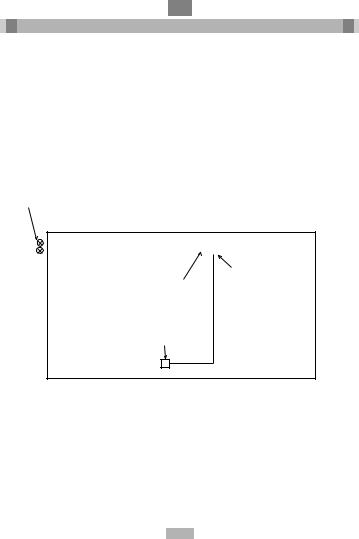
●Below is a diagram of a typical installation for the RD1.
Isolating solenoid valves positioned in the gas and liquid lines (optional – supplied by installer)
|
|
|
|
|
|
|
|
Hotel room |
|
|
|
|
|
|
|
Power source |
|
|
|
|
|
|
|
|
||
|
|
|
FCU |
|
|
|
|
230V~50Hz |
|
|
|
|
|
|
(from FCU) |
||
|
|
|
|
|
|
|
||
|
|
|
|
|
|
|
|
|
Control
Unit
FCU Interface Cable
Remote sensor/audible
 alarm interconnecting
cable
Metal oxide refrigerant detector. Low level position
9

GB
System Overview
●A standard RBC-RD2-PE installation would be in the compressor housing of the MMS (Modular Multi System) outdoor unit.
●As the MMS is designed for up to five outdoor units, it would mean up to five detectors would be required per system.
●All the detectors will be connected together in series and connected to the Inverter unit electrical box.
●The refrigerant sensor forms an integral part of the control box. Therefore control box must be located within 200mm (maximum height) from the compressor housing base.
●If solenoid valves (optional: to be supplied by the installer) are to be installed, then it is recommended that the valves are located on the outside of the outdoor unit, but before the pipe work joins the common refrigeration circuit.
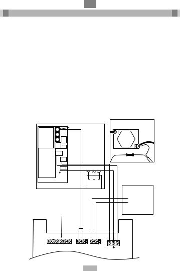
●Below is a diagram showing where to locate the control unit in the MMS outdoor.
|
|
Fuse |
|
|
CDU Interface |
PCB |
|
cable (only on |
|
inverter) |
|
|
L1 |
To solenoid |
|
|
valves |
PCB |
N |
|
|
|
|
|
Control Unit |
|
● Using the supplied bracket, unscrew the right hand screw form the compressor mounting base, locate bracket and replace screw into the compressor base. Ensuring the screw is fully tightened.
10
GB
Electrical Wiring – RD1
●There are various options when installing a RD1 unit, firstly it can be installed as a stand alone unit. Secondly it can be installed with any AI indoor unit (‘4’ Series and MMS indoors), this will enable fault codes to be generated and the indoor unit can be shut down. Thirdly solenoid valves can also be installed as an optional extra.
●Ensure that the control unit is protected with a 1A 240VAC fuse.
●The maximum rating of the solenoid relay is 240V~ 5A.
●It must be noted that any solenoids valves selected for this application must be capable of operating at a pressure of 33bar and with the flow being bi-directional.
●If rear entry is required, Ø16mm holes can be made in the rear of the control box. Centre marks for the holes are provided.
Remote Sensor |
Indoor Unit |
||
|
|||
Assembly |
|
||
|
|
|
PCB |
TOP |
|
TOP |
|
MAKE |
+ |
– Buzz Sig |
RAV = CN17 |
|
|
MM = CN21 |
|
|
|
|
|
COM |
|
|
|
2 Core |
Solenoid Valves |
|
(Optional) |
||
Cable |
||
|
(Supplied)
Volt Free Relay
Contacts
Max Rating 240V~5A
230V 50Hz
1A Supply
+ sig – mute + buzzer |
AI |
ALARM |
L |
|
|
N |
11

GB
Electrical Wiring – RD1
●Mount the control box (mounting dimensions on rear of control box) near to the indoor unit. Mount the remote sensor assembly to a standard flush or surface mount pattress low down in the room.
●From the remote sensor assembly connect a 6-core cable to the control unit, as shown in the above wiring diagram.
●Connect the control unit to a fused (1A 240VAC) power supply using a 3-core cable, the power can be derived from the indoor unit if desired. Please refer to the above wiring diagram.
●If the refrigerant detector is to be integrated with either a AI ‘4’ series RAV system or MM system. Then the FCU interface cable (supplied) is required to be connected to the indoor PCB. Please refer to the above wiring diagram.
oIf the detector is to be connected to a RAV AI system, then connect the FCU interface cable to CN17 on the indoor PCB.
oIf the detector is to be connected to a MM system, then connect the FCU interface cable to CN21 on the indoor PCB.
●If solenoid valves are to be used, then an additional 2-core cable will be required to connect to the volt free NC relay contacts. The maximum rating of the contacts are 240V @ 5A, if this is not sufficient then an additional power relay or contactor must be used. Please refer to the above wiring diagram.
12
GB
Electrical Wiring – RD2
●Mount the RD2 inside the compressor housing as shown in the System Overview section of this manual.
●Connect a 3-core supply cable from the control unit to the electrical box on the outdoor unit, please refer to the wiring diagram below. Ensure a 1A fuse is fitted, to protect the control unit.
●If only one CDU is used then connect the CDU interface cable from the control unit to the electrical box on the outdoor unit.
o Firstly locate the three ceramic fuses at the top of the electrical box.
o From the top fuse (red cables) remove the thin (AWG20) red cable from the right side of the fuse, and in its place fit the CDU interface cable with the ring crimp terminal on the end.
o From the thin (AWG20) cable just removed from the fuse, cut off the ring terminal and strip 5mm of insulation. Place into the crimp butt joint, and crimp firmly.
|
|
CDU Connection Detail |
Fuse |
|
|
|
CDU |
(red) |
PCB |
Interface |
|
|
cable (only |
|
|
on inverter) |
|
L1 |
2-Core cable |
|
(Supplied) |
|
|
|
|
|
N |
|
Crimp |
PCB |
|
|
|
|
Solenoid Valves |
|
|
Volt free relay |
|
|
contacts, |
No connection |
|
Max rating |
|
240V~5A |
|
required, as unit uses |
|
|
|
|
|
internal sensor |
|
|
+ sig – mute + buzzer AI |
ALARM |
N |
L |
|
|
13

GB
Electrical Wiring – RD2
●If more than one CDU is installed (max 5 – 46HP), then each refrigerant detector must be connected in series to the unit in the inverter CDU. The CDU interface cable is only required in the inverter CDU.
●Connect each refrigerant detector using 3-core cable to the L1, N and earth terminals in each CDU. Each detector unit must be protected by a 1A 240VAC fuse.
●Connect the AI control cable as shown below:
Connect to Inverter
Electrical Box
AI |
AI |
AI |
AI |
AI |
CDU #5 |
CDU #4 |
CDU #3 |
CDU #2 |
CDU #1 |
(Fix) |
(Fix) |
(Fix) |
(Fix) |
(Inv) |
●Then to complete the loop connect the cables to the inverter electrical box, as described on the previous page.
●If solenoid valves are to be used, then an additional 2-core cable will be required to connect to the volt free NC relay contacts. The maximum rating of the contacts are 240V @ 5A, if this is not sufficient then an additional power relay or contactor must be used. Please refer to the above wiring diagram.
●It must be noted that any solenoids valves selected for this application must be capable of operating at a pressure of 33bar and with the flow being bi-directional.
14

F
Avertissement
Ce manuel contient les instructions d’installation pour les Détecteurs de Fuites de Réfrigérant RBC-RD1-PE et RBC-RD2-PE. Prière de lire ces instructions attentivement avant de procéder au travail d’installation.
 Cet équipement doit être installé par des personnes adéquatement formées.
Une installation erronée par du personnel non qualifié peut entraîner un mauvais fonctionnement des détecteurs de réfrigérant, des électrocutions ou des incendies.
En toutes circonstances, s’assurer que les pratiques de travail sûres sont respectées. Suivre les précautions d’usage concernant les personnes situées à proximité des travaux.
S’assurer que toutes les réglementations locales, nationales et internationales sont respectées.
Avant de procéder à l’installation, s’assurer que toutes les alimentations électriques appropriées sont mises hors circuit.
Déballer soigneusement l’équipement et vérifier qu’il n’est pas endommagé et  qu’aucune pièce ne manque. Prière de signaler immédiatement tout dommage éventuel ou toute pièce manquante.
Si des électrovannes sont utilisées, s’assurer qu’elles sont conçues pour résister à des  températures hautes/basses ainsi qu’aux pressions du réfrigérant et qu’elles peuvent
fonctionner en écoulement bidirectionnel.
Les détecteurs de réfrigérant sont conformes aux Directives CE : 73/23/EEC – Directive Basse Tension
89/336/EEC – Compatibilité Electromagnétique
Par conséquent, les détecteurs de réfrigérant sont désignés pour un usage en milieux commercial et industriel.
|
|
|
Liste des Composants |
|
|
Composants des Détecteurs de Réfrigérant : |
|
|
|||
RBC-RD1-PE: |
Boîte de commande & capuchons de vis |
|
|
||
|
|
|
Ensemble de sonde à distance /d’alarme sonore |
|
|
|
|
|
Câble d’interface de FCU |
|
|
|
|
|
Instructions d’installation |
|
|
|
|
|
Mode d’emploi |
|
|
RBC-RD2-PE: |
Boîte de commande avec sonde intégrée & capuchons de vis |
|
|
||
|
|
|
Câble d’interface de CDU |
|
|
|
|
|
Instructions d’installation |
|
|
|
|
|
Mode d’emploi |
|
|
Support de montage
Vis x4
15

F
Spécifications
Modèle |
|
RBC-RD1-PE |
RBC-RD2-PE |
|
|
|
|
|
|
Description |
|
Détecteur de réfrigérant |
Détecteur de réfrigérant |
|
|
|
intérieur |
extérieur |
|
Sonde à distance & |
|
Standard |
Pas applicable |
|
Avertisseur sonore |
|
|||
|
|
|
||
|
Phase |
Mono |
Mono |
|
Alimentation |
Volts |
220 - 240 |
220 - 240 |
|
Hz |
50 |
50 |
||
|
||||
|
mA |
300 |
300 |
|
Type de Réfrigérant |
|
HFC 407C |
HFC 407C |
|
Couleur |
|
Gris |
Gris |
|
Hauteur |
mm |
80 (102) |
80 (102) |
|
(avec presse-étoupe) |
|
|
|
|
Largeur |
mm |
160 |
160 |
|
Profondeur |
mm |
55 |
55 |
|
Compatibilité |
|
Toutes les Séries RAV AI |
Uniquement les unités |
|
|
|
"4" & les unités |
extérieures MMS |
|
|
|
intérieures MMS |
|
Caractéristiques |
|
RBC-RD1-PE |
RBC-RD2-PE |
Alarme de Bas Niveau |
ppm |
250 |
Pas applicable |
Alarme de Haut Niveau ppm |
1000 |
1000 |
|
Alarme d’inondation |
ppm |
2200 |
2200 |
Panne de Sonde |
|
2 types: < 4 h. & > 4 h. |
1 type: >4 h. |
Code de Faute |
B6 |
04 |
|
|
Bas |
B5 |
N/A |
Codes de Faute |
Haut |
B6 |
04 |
Inondation |
B6 |
04 |
|
Fermeture de Vanne |
|
Sortie de relais N.F. à tension |
Sortie de relais N.F. à tension |
(en option) |
|
nulle |
nulle |
Puissance de Sortie |
|
240V~ 5Amp |
240V~ 5Amp |
des Relais |
|
||
|
|
|
|
Longévité de la Sonde |
|
|
|
Années |
5 - 7 |
5 – 7 |
|
Alarme Sonore |
|
Oui (>80dBA) |
Non |
16

F
Différentiation des Modèles
●Deux modèles sont disponibles, le premier étant le RBC-RD1-PE. Le RD1 est conçu pour une installation à côté de l’unité intérieure, avec la sonde à distance et l’alarme sonore situées à bas niveau et de préférence sous l’unité intérieure.
●Le RD1 est conçu uniquement pour une utilisation avec les unités intérieures MMS et les unités intérieures AI de la Série RAV ‘4’.
●Le second modèle est le RBC-RD2-PE. Ce modèle (RD2) est conçu pour une utilisation avec l’unité extérieure Modular Multi. L’unité devra être placée à l’intérieur du carter de compresseur et comprend une sonde interne.
●Le RD2 ne peut être monté que sur l’unité extérieure MMS.
●La fonctionnalité des deux systèmes sera décrite dans la section sur le fonctionnement intérieur et extérieur de ce manuel.
Réglage de l’Unité
●Il y a deux cartes de circuit imprimé de commande à l’intérieur du détecteur de réfrigérant, chacune avec des cavaliers permettant la mise en/hors service de fonctions spécifiques. Les diagrammes ci-dessous montrent la position de ces cavaliers.
|
AJP |
|
BJP |
|
+ sig – mute + buzzer |
AI |
ALARM |
N |
L |
|
|
|
||
|
|
|
carte de commande |
|
A B C
JP
Carte de Circuit Imprimé Secondaire
17

F
Réglage de l’Unité
La fonction des cavaliers est listée ci-dessous :
Cavalier |
RBC-RD1-PE |
RBC-RD2-PE |
|
|
|
A |
Pas Utilisé |
Pas Utilisé |
|
|
|
B |
Pas Présent |
Présent |
C |
Pas Utilisé |
Pas Utilisé |
JP |
Désactive l’arrêt d’unité |
Désactive l’arrêt d’unité |
AJP |
Ferme les contacts d’Alarme |
Ferme les contacts d’Alarme |
|
|
|
BJP |
Présent |
Pas Présent |
|
|
|
Parmi les cavaliers ci-dessus, seuls les "JP" et "AJP" sont utilisables.
●JP : Si ce cavalier est retiré, l’unité intérieure ou le système extérieur ne s’arrêtera pas (les codes de faute B6 – intérieur, et 04 – extérieur ne seront donc pas produits). Il n’est pas recommandé de retirer ce cavalier à moins qu’il soit impératif que le système continue à fonctionner.
●AJP : Si ce cavalier est en place, les contacts de l’Alarme (relais d’électrovanne) sont fermés. Ceci ne dépend pas du fait que l’unité est sous tension ou non. Le rôle principal de ce cavalier est pour la mise en service. Si des vannes sont en place, le système de climatisation peut fonctionner, même si le détecteur n’est pas en service ou sous tension.
●Tous les autres cavaliers doivent être mis en place comme indiqué dans le tableau pour assurer le fonctionnement du système.
18

F
Vue d’ensemble du Système
●Une installation typique du RBC-RD1-PE serait dans une chambre d’hôtel ou dans un bureau.
●L’ensemble de la sonde à distance doit être placé en position basse dans la pièce, par exemple à la même hauteur que les prises de courant, etc. La position de la sonde est également importante. La position recommandée est sous l’unité intérieure ou sous la tuyauterie de réfrigérant de l’unité intérieure.
●Pour assurer un bon fonctionnement, les points (listés ci-dessous) doivent être suivis durant l’installation:
o La hauteur maximale de la sonde au-dessus du sol doit être de 300 mm.
o Une ventilation adéquate doit être maintenue près de l’ensemble de sonde.
o La distance minimale recommandée entre l’ensemble de sonde et d’autres objets dans la pièce est de 500 mm.
o Le détecteur doit être monté à un endroit où les courants d’air ne peuvent pas influencer son fonctionnement.
19

F
Vue d’ensemble du Système
●L’ensemble de sonde a été conçu de façon à pouvoir être installé dans n’importe quel support arrière standard encastré ou monté en surface. L’ensemble de sonde à distance a été fabriqué dans une plaque à grille électrique standard, pour maximiser le nombre de plaques de fermeture disponibles à l’installateur.
●L’unité de commande principale est conçue pour être positionnée juste en dessous du plafond, à côté de l’unité intérieure.
●Si des électrovannes (en option : à fournir par l’installateur) doivent être installées, il est recommandé de placer celles-ci en dehors de la zone couverte par le détecteur.
●Voir diagramme d’une installation typique du RD1 ci-dessous.
Electrovannes d’isolement situées dans les lignes de gaz et liquides
(en option – fournies par l’installateur)
|
|
|
|
|
|
|
|
|
|
|
Chambre d’hôtel |
|
|
|
|
|
|
|
|
|
|
|
Source |
|
|
|
|
|
|
|
|
|
|
|
|
|
|
|
FCU |
|
|
|
|
|
d’alimentation |
||
|
|
|
|
|
|
|
|
230V~50Hz |
|||
|
|
|
|
|
|
|
|
|
|
|
(du FCU) |
|
|
|
|
|
|
|
|
Unité de |
|||
|
|
|
Câble d’Interface de FCU |
Commande |
|||||||
|
|
|
|
|
|
|
|||||
|
|
|
|
|
|
|
|
|
|
Câble de |
|
|
|
|
|
|
|
|
|
|
|
raccordement |
|
|
|
|
|
|
|
|
|
|
|
de sonde à distance |
|
|
|
|
|
|
|
|
|
|
|
/ d’alarme sonore |
|
|
|
Détecteur de réfrigérant à oxyde métallique. |
|
|
|
|
|||||
|
|
Position niveau bas |
|
|
|
|
|||||
|
|
|
|
|
|
|
|
|
|
|
|
|
|
|
|
|
|
|
|
|
|
|
|
|
|
|
|
|
|
|
|
|
|
|
|
20
F
Vue d’ensemble du Système
●Une installation standard du RBC-RD2-PE serait à l’intérieur du carter de compresseur de l’unité extérieure du MMS (Système Modular Multi).
●Etant donné que le MMS est conçu pour un fonctionnement avec jusqu’à cinq unités extérieures, jusqu’à cinq détecteurs par système peuvent être requis.
●Tous les détecteurs seront connectés ensemble en série et raccordés à la boîte électrique de l’unité d’Inverseur.
●La sonde de réfrigérant forme une partie intégrante de la boîte de commande. La boîte de commande doit donc être positionnée à moins de 200 mm (hauteur maximale de la base du carter de compresseur.
●Si des électrovannes (en option : à fournir par l’installateur) doivent être installées, il est recommandé que celles-ci soient situées à l’extérieur de l’unité extérieure, mais avant le raccordement de la tuyauterie avec le circuit de réfrigération commun.
●Voir diagramme ci-dessous illustrant l’emplacement de l’unité de commande dans le MMS extérieur.
|
Fusible |
Carte de |
Cable d’interface |
de CDU |
|
Circuit |
(seulement |
imprimé |
sur inverseur) |
L1 |
Vers |
Carte de |
électrovannes |
Circuit |
N |
imprimé |
|
Unité de Commande |
|
● En utilisant le support fourni, dévisser la vis avec pas à droite du socle de fixation du compresseur, positionner le support, puis remettre la vis dans le socle du compresseur. S’assurer que la vis est serrée à fond.
21

F
Câblage Electrique – RD1
●Plusieurs options existent lors de l’installation d’une unité RD1. Premièrement, elle peut être installée comme une unité indépendante. Deuxièmement, elle peut être installée avec toute unité intérieure AI (Série ‘4’ et MMS intérieur), ce qui permet de produire des codes de fautes et d’arrêter l’unité intérieure. Troisièmement, des électrovannes peuvent également être installées en option.
●S’assurer que l’unité de commande est protégée avec un fusible de 1 Amp 240VCA.
●La puissance nominale maximale du relais de solénoïde est 240V ~ 5 Amp.
●Il est à noter que toute électrovanne choisie pour cette application doit être capable de fonctionner sous une pression de 33 bars et avec un écoulement bidirectionnel.
●Si une entrée par l’arrière est requise, des trous de Ø16 mm peuvent être faits dans l’arrière de la boîte de commande. Le centre des trous est marqué.
Ensemble de Sonde |
Unité Intérieure |
||
|
|||
à Distance |
|
||
|
|
|
Carte de |
TOP |
|
TOP |
Circuit imprimé |
|
|
||
MAKE |
+ |
– Buzz Sig |
RAV = CN17 |
|
|
MM = CN21 |
|
|
|
|
|
COM |
|
|
|
Câble à |
Electrovannes |
2 âmes |
(En option) |
(Fourni) |
|
Contacts de Relais à Tension Nulle Puissance Max. 240V ~ 5 Amp
Alimentation
1 Amp 230V 50Hz
+ sig – mute + buzzer |
AI |
ALARM |
L |
|
|
N |
22
 Loading...