


|
|
|
|
|
|
|
|
INSTALLATION MANUAL |
|
|
|
|
|
|
|
|
|
MANUEL D’INSTALLATION |
|
|
|
|
|
|
|
|
|
||
|
|
|
|
|
|
|
|
||
|
|
|
|
|
|
|
G-INSTALLATIONS-HANDBUCH |
||
|
|
|
|
|
|
|
|||
|
|
|
|
|
|
|
|
MANUALE DI INSTALLAZIONE |
|
|
|
|
|
|
|
|
|
||
|
|
|
|
|
|
|
|
MANUAL DE INSTALACIÓN |
|
|
|
|
|
|
|
|
|
ЕГЧЕЙСЙДЙП ЕГКБФБУФБУЗУ |
|
|
|
|
|
|
|
|
|
MANUAL DE INSTALAÇÃO |
|
|
|
|
|
|
|
|
|
INSTALLATIONSHANDBO |
|
|
|
|
|
|
|
|
|
Not accessible to the general public |
|
|
|
|
|
|
|
|
|
Vente interdite au grand public |
|
|
|
|
|
|
|
|
|
Kein öffentlicher Zugang |
|
|
|
|
|
|
|
|
|
Non accessibile a clienti generici |
|
AIR CONDITIONER (SPLIT TYPE) |
No destinado al público en general |
||||||||
Мз рспувЬуймп брь фп генйкь кпйнь |
|||||||||
CLIMATISEUR (TYPE SPLIT) |
|
||||||||
|
Não acessível ao público em geral |
||||||||
KLIMAGERÄT (SPLIT-TYP) |
Inte tillgänglig för allmänheten |
|
CONDIZIONATORE D'ARIA (TIPO SPLIT) |
||
|
||
AIRE ACONDICIONADO (TIPO SPLIT) |
|
КЛЙМБФЙУФЙКП (ДЙБЙСПХМЕНПХ ФХРПХ)
AR CONDICIONADO (TIPO SPLIT)
LUFTKONDITIONERINGSAPPARAT (SPLIT TYP)
<4-Way Air Discharge Cassette Type> <Type cassette à 4 voies de soufflage> <4-Wege-Belüftungskassette>
<Tipo a cassetta con scarico d'aria a 4 vie> <Modelo de casete de distribución de aire de 4 vías>
<ЕкспЮ бЭсб 4-Дйехиэнуещн Фэрпх КбуЭфбт>
<Descarga de ar tipo cassete de 4 vias>
<Apparat med 4-vägars luftutsläpp>
Indoor Unit
Unité intérieure/Raumeinheit/Unità interna/Unidad interior
ЕущфесйкЮ МпнЬдб/Unidade interior/


 /Inomhusenhet
Heat Pump Model Modèle à thermopompe Geräte mit Heizung
Modello con pompa di riscaldamento Modelo con bomba de calor
МпнфЭлп ме БнфлЯб Иесмьфзфбт
Modelo de bomba térmica
Värmepumpsmodell
Cooling Only Model Modèle à froid seul Geräte nur zur Kühlung
Modello solo per raffreddamento Modelo de refrigeración únicamente
МпнфЭлп Шэозт брпклейуфйкЬ
Modelo Apenas para Refrigeração
Modell endast för avkylning
RAS-M10SMUV-E RAS-M13SMUV-E RAS-M16SMUV-E
RAS-M10SMUCV-E RB-B11MC(W)E RAS-M13SMUCV-E RAS-M16SMUCV-E
ADOPTION OF NEW REFRIGERANT
This Air Conditioner is a new type which adopts the new refrigerant HFC (R410A) instead of the conventional refrigerant R22. R410A is an ozone friendly refrigerant.
Please read this Installation Manual carefully before installing the Air Conditioner.
•This Manual describes the installation method of the indoor unit.
•For installation of the outdoor unit, follow the Installation Manual attached to the outdoor unit.
UTILISATION DU NOUVEAU REFRIGERANT
Ce nouveau type de climatiseur utilise le nouveau réfrigérant HFC (R410A) au lieu du traditionnel R22. Le R410A est un réfrigérant qui respecte la couche d’ozone.
Veuillez lire attentivement ce Manuel d’installation avant d’installer le climatiseur.
•Ce manuel décrit la procédure d’installation de l’unité intérieure.
•Pour installer l’unité extérieure, reportez-vous au Manuel d’installation fourni avec l’unité extérieure.
EINFÜHRUNG EINES NEUEN KÜHLMITTELS
Dies ist ein neuartiges Klimagerät. Anstatt des herkömmlichen Kältemittels R22 verwendet es das neue HFC Kältemittel R410A. R410A schont die Ozonschicht.
Bitte lesen Sie dieses Handbuch sorgfältig, bevor Sie mit der Installation des Klimagerätes beginnen.
•In diesem Handbuch wird die Installation der Inneneinheit beschrieben.
•Um die Außeneinheit zu installieren, folgen Sie den Anweisungen des Handbuchs, das der Außeneinheit beiliegt.
ADOZIONE DI UN NUOVO REFRIGERANTE
Questo condizionatore d’aria è di dipo nuovo e impiega il nuovo refrigerante HFC (R410A) invece del R22, tradizionalmente usato. R410A è un refrigerante ecologicamente rispettoso dello strato d’ozono.
Prima di eseguire l’installazione del condizionatore d’aria, leggere attentamente il Manuale d’installazione.
•Questo manaule il metodo d’installazione dell’unità interna.
•Per l’installazione dell’unità esterna, fare riferimento al Manuale d’installazione fornito con l’unità esterna.
ADOPCIÓN DE NUEVO REFRIGERANTE
Este acondicionador de aire es un tipo Nuevo que adopta el refrigerante nuevo HFC (R410A) en vez del refrigerante convencional R22. El R410A es un refrigerante que no daña la capa de ozono.
Lea atentamente este Manual de instalación antes de proceder a la instalación del aparato de aire acondicionado.
•Este manual describe el método de instalación de la unidad interior.
•Para la instalación de la unidad exterior, consulte el Manual de instalación que acompaña a la unidad exterior.
ХЙПИЕФЗУЗ НЕПХ ШХКФЙКПХ |
Рбсбкблю дйбвЬуфе рспуечфйкЬ фп ЕгчейсЯдйп ЕгкбфЬуфбузт |
|
рсйн брь фзн егкбфЬуфбуз фпх Клймбфйуфйкпэ. |
||
|
Фп рбсьн Клймбфйуфйкь еЯнбй нЭпх фэрпх кбй хйпиефеЯ фп нЭп шхкфйкь HFC (R410A) бнфЯ гйб фп ухмвбфйкь шхкфйкь R22. Фп R410A еЯнбй Энб шхкфйкь цйлйкь щт рспт фп ьжпн.
•Фп рбсьн ЕгчейсЯдйп ресйгсЬцей фз мЭипдп егкбфЬуфбузт фзт еущфесйкЮт мпнЬдбт.
•Гйб фзн егкбфЬуфбуз фзт еощфесйкЮт мпнЬдбт, ухмвпхлехфеЯфе фп ЕгчейсЯдйп ЕгкбфЬуфбузт рпх ухнпдеэей фзн еощфесйкЮ мпнЬдб.
ADOPÇÃO DO NOVO REFRIGERANTE
O presente aparelho de ar condicionado é um novo tipo que adopta o novo refrigerante HFC (R410A) em vez do refrigerante convencional R22. O R410A é um refrigerante que não prejudica o ozono.
Leia atentamente o presente Manual de Instalação antes de instalar o Ar Condicionado.
•O presente manual descreve o método de instalar a unidade interior.
•Para a instalação de uma unidade exterior, siga o Manual de Instalação que acompanha a unidade exterior.
ANVÄNDANDE AV NY KYLVÄTSKA
Denna luftkonditioneringsapparat är en ny typ som använder den nya kylvätskan HFC (R410A) i stället för den vanliga kylvätskan R22. R410A är en kylvätska som inte är skadlig för ozonskiktet.
Vänligen läs denna Installationshandbok noga innan du installerar luftkonditioneringsapparaten.
•Denna handbok beskriver hur inomhusenheten ska installeras.
•För installation av utomhusenheten, följ Installationshandboken som är ansluten till utomhusenheten.
CONTENTS
Accessory parts and Parts to be procured locally ...................... |
1 |
6 |
EVACUATING ........................................................................ |
14 |
|
1 |
PRECAUTIONS FOR SAFETY ............................................... |
2 |
7 |
ELECTRICAL WORK ............................................................ |
15 |
2 |
SELECTION OF INSTALLATION PLACE .............................. |
4 |
8 |
APPLICABLE CONTROLS ................................................... |
18 |
3 |
INSTALLATION OF INDOOR UNIT ........................................ |
6 |
9 |
TEST OPERATION ................................................................ |
20 |
4 |
DRAIN PIPING WORK .......................................................... |
10 |
10 |
INSTALLATION / SERVICING TOOLS .................................. |
20 |
5 |
REFRIGERANT PIPING AND EVACUATING ....................... |
13 |
11 |
MAINTENANCE .................................................................... |
21 |
|
|
|
|
||
|
|
SOMMAIRE |
|
||
Pièces accessoires et pièces non fournies ............................... |
22 |
6 |
EVACUATION DE L’AIR ........................................................ |
35 |
|
1 |
MESURES DE SECURITE .................................................... |
23 |
7 |
INSTALLATION ELECTRIQUE ............................................. |
36 |
2 |
SELECTION DU LIEU D’INSTALLATION ............................ |
25 |
8 |
COMMANDES APPLICABLES ............................................ |
39 |
3 |
INSTALLATION DE L’UNITE INTERIEURE .......................... |
27 |
9 |
ESSAI DE FONCTIONNEMENT ........................................... |
41 |
4 |
INSTALLATION DES TUYAUX D’EVACUATION ................... |
31 |
10 |
OUTILS D’INSTALLATION/D’ENTRETIEN .......................... |
41 |
5 |
TUYAUTERIE DE FRIGORIGÈNE ET ÉVACUATION ........... |
34 |
11 |
ENTRETIEN .......................................................................... |
42 |
|
|
|
|
|
|
|
|
INHALT |
|
|
|
Zubehör und bauseits bereitzustellende Teile ........................... |
43 |
6 |
ENTLÜFTEN DER ROHRLEITUNGEN ................................ |
56 |
|
1 |
SICHERHEITSVORKEHRUNGEN ........................................ |
44 |
7 |
ELEKTROINSTALLATION .................................................... |
57 |
2 |
AUSWAHL DES AUFSTELLUNGSORTES .......................... |
46 |
8 |
STEUERUNGSMÖGLICHKEITEN........................................ |
60 |
3 |
INSTALLATION DER RAUMEINHEIT ................................... |
48 |
9 |
TESTLAUF ............................................................................ |
62 |
4 |
INSTALLATION DES KONDENSWASSER-ABLAUFS ........ |
52 |
10 |
INSTALLATIONS / WARTUNGSWERKZEUGE .................... |
62 |
5 |
KÜHLMITTELLEITUNGSSYSTEM UND ENTLÜFTUNG |
.... 55 |
11 |
WARTUNG ............................................................................ |
63 |
|
|
|
|
|
|
|
|
INDICE |
|
|
|
Accessori e parti da acquistare sul posto ................................. |
64 |
6 |
SPURGO ............................................................................... |
77 |
|
1 |
PRECAUZIONI PER LA SICUREZZA .................................. |
65 |
7 |
ESECUZIONE DEI COLLEGAMENTI ELETTRICI ............... |
78 |
2 |
SCELTA DEL POSTO D’INSTALLAZIONE .......................... |
67 |
8 |
COMANDI UTILIZZABILI ...................................................... |
81 |
3 |
INSTALLAZIONE DELL’UNITÀ INTERNA ........................... |
69 |
9 |
FUNZIONAMENTO DI PROVA .............................................. |
83 |
4 |
LAVORO PER TUBAZIONE DI SCARICO ............................ |
73 |
10 |
ATTREZZI PER L'INSTALLAZIONE/PER LA MANUTENZIONE ... |
83 |
5 |
TUBAZIONI DEL REFRIGERANTE E SCARICO ................ |
76 |
11 |
MANUTENZIONE .................................................................. |
84 |
|
|
|
|||
|
CONTENIDO |
|
|||
Componentes accesorios y componentes de suministro local |
..... 85 |
6 |
EVACUACIÓN ........................................................................ |
98 |
|
1 |
PRECAUCIONES PARA SU SEGURIDAD ........................... |
86 |
7 |
TRABAJOS EN EL SISTEMA ELÉCTRICO ........................ |
99 |
2 |
SELECCIÓN DEL LUGAR DE INSTALACIÓN ..................... |
88 |
8 |
CONTROLES APLICABLES .............................................. |
102 |
3 |
INSTALACIÓN DE LA UNIDAD INTERIOR .......................... |
90 |
9 |
FUNCIONAMIENTO DE PRUEBA ...................................... |
104 |
4 |
CANALIZACIÓN DE DRENAJE ........................................... |
94 |
10 |
HERRAMIENTAS DE INSTALACIÓN/REPARACIÓN ........ |
104 |
5 |
TUBOS DE REFRIGERANTE Y EVACUACIÓN ................... |
97 |
11 |
MANTENIMIENTO ............................................................... |
105 |
|
|
|
|||
|
РЕСЙЕЧПМЕНБ |
|
|||
Рбселкьменб бнфбллбкфйкЬ кбй ЕобсфЮмбфб брь фзн фпрйкЮ бгпсЬ |
... 106 |
6 |
ЕККЕНЩУЗ ......................................................................... |
119 |
|
1 |
РСПЦХЛБОЕЙУ БУЦБЛЕЙБУ ............................................. |
107 |
7 |
ЗЛЕКФСПЛПГЙКБ .............................................................. |
120 |
2 |
ЕРЙЛПГЗ ФПХ ЧЩСПХ ЕГКБФБУФБУЗУ ......................... |
109 |
8 |
ЕЦБСМПУЙМПЙ ЕЛЕГЧПЙ .................................................. |
123 |
3 |
ЕГКБФБУФБУЗ ФЗУ ЕУЩФЕСЙКЗУ МПНБДБУ ............... |
111 |
9 |
ДПКЙМБУФЙКЗ ЛЕЙФПХСГЙБ ............................................ |
125 |
4 |
ЕГКБФБУФБУЗ УЩЛЗНЩУЕЩН БРПУФСБГГЙУЗУ ......... |
115 |
10 |
ЕСГБЛЕЙБ ЕГКБФБУФБУЗУ/ ЕРЙУКЕХЗУ ....................... |
125 |
5 |
УЩЛЗНЩУЕЙУ ШХОЗУ КБЙ БРПУФСБГГЙУЗУ .................. |
118 |
11 |
УХНФЗСЗУЗ ....................................................................... |
126 |
|
|
|
|
|
|
|
|
ÍNDICE |
|
|
|
Acessórios e peças adquiridas localmente ............................. |
127 |
6 |
EXPURGO ........................................................................... |
140 |
|
1 |
PRECAUÇÕES DE SEGURANÇA ..................................... |
128 |
7 |
LIGAÇÕES ELÉCTRICAS .................................................. |
141 |
2 |
SELECÇÃO DO LOCAL DE INSTALAÇÃO ....................... |
130 |
8 |
CONTROLOS APLICÁVEIS ............................................... |
144 |
3 |
INSTALAÇÃO DA UNIDADE INTERIOR ............................ |
132 |
9 |
OPERAÇÃO DE TESTE ...................................................... |
146 |
4 |
INSTALAÇÃO DA TUBAGEM DE DRENAGEM ................. |
136 |
10 |
FERRAMENTAS DE INSTALAÇÃO/REPARO ................... |
146 |
5 |
TUBAGEM DE REFRIGERANTE E EVACUAÇÃO ............ |
139 |
11 |
MANUTENÇÃO ................................................................... |
147 |
INNEHÅLL
Tillbehör och delar som anförskaffas lokalt ............................ |
169 |
6 |
TÖMNING ............................................................................ |
182 |
|
1 |
FÖRSIKTIGHETSÅTGÄRDER ........................................... |
170 |
7 |
ELEKTRISKT ARBETE ...................................................... |
183 |
2 |
VAL AV INSTALLATIONSPLATS ........................................ |
172 |
8 |
TILLÄMPBARA KONTROLLER ......................................... |
186 |
3 |
INOMHUSENHETENS INSTALLATION ............................. |
174 |
9 |
TESTFUNKTION ................................................................. |
188 |
4 |
ARBETE MED TÖMNINGSRÖREN .................................... |
178 |
10 |
INSTALLATION / SERVICEVERKTYG ............................... |
188 |
5 |
KYLVÄTSKANS RÖRLEDNING OCH TÖMNING .............. |
181 |
11 |
UNDERHÅLL ...................................................................... |
189 |
PORTUGUКS ЕЛЛЗНЙКБ ESPAСOL ITALIANO DEUTSCH FRANCAIS ENGLISH
SVENSKA

Accessory parts and Parts to be procured locally
H Accessory parts
Part name |
Q’ty |
Shape |
Usage |
Installation Manual |
1 |
This manual |
(Be sure to hand over to customers) |
Wireless remote controller |
1 |
|
— |
Remote controller holder |
1 |
|
— |
Mounting screws for remote |
1 |
|
— |
controller holder |
|
||
3.1 mm (diam.) × 16 mm |
|
|
|
Batteries (Manganese) |
2 |
|
— |
Heat insulating pipe |
2 |
|
For heat insulation of pipe connecting section |
Installation pattern |
1 |
—— |
For confirmation of ceiling opening and main unit position |
Installation gauge |
2 |
|
For positioning of ceiling position |
|
(united with installation pattern) |
||
|
|
|
|
Pattern fixing screw |
4 |
M5 × 16L |
For attach the installation pattern |
Heat insulator |
1 |
|
For heat insulation of drain connecting section |
Washer |
8 |
|
For hanging-down unit |
|
|
||
Hose band |
1 |
|
For connecting drain pipe |
Flexible hose |
1 |
|
For adjusting core-out of drain pipe |
Heat insulator A |
1 |
|
For sealing of wire connecting port |
Heat insulator B |
1 |
|
For sealing of wire connecting port |
Owner’s Manual |
1 |
|
(Be sure to hand over to customers) |
<Separate sold parts>
Part name |
Q’ty |
Shape |
Usage |
Ceiling panel |
1 |
|
Model : RB-B11MC(W)E |
H Parts to be procured locally
Connecting pipe (Liquid side)
(6.4 mm (diam.), Nominal (diam.) 1/4” thick 0.8 mm)
Connecting pipe (Gas side)
(9.5 mm (diam.), Nominal (diam.) 3/8” thick 0.8 mm) RAS-M10SMUV-E, RAS-M10SMUCV-E, RAS-M13SMUV-E, RAS-M13SMUCV-E
(12.7 mm (diam.), Nominal (diam.) 1/2” thick 0.8 mm) RAS-M16SMUV-E, RAS-M16SMUCV-E
Power supply cord
2.5 mm² (H07RN-F or 60245IEC66)
Connecting wire
H07RN-F or 60245IEC66 (1.0 mm²)
Thermal insulation for refrigerant pipe
(10 mm or more, thermal insulating foam polyethylene)
Thermal insulation for drain pipe (10 mm or more, foam polyethylene)
Drain pipe (Outer 26 mm (diam.))
Tapes
Grounding wire (1.6 mm (diam.) or more)
1
1 PRECAUTIONS FOR SAFETY
•Ensure that all Local, National and International regulations are satisfied.
•Read this “PRECAUTIONS FOR SAFETY” carefully before Installation.
•The precautions described below include the important items regarding safety. Observe them without fail.
•After the installation work, perform a trial operation to check for any problem.
Follow the Owner’s Manual to explain how to use and maintain the unit to the customer.
•Turn off the main power supply switch (or breaker) before the unit maintenance.
•Ask the customer to keep the Installation Manual together with the Owner’s Manual.
CAUTION New Refrigerant Air Conditioner Installation
•THIS AIR CONDITIONER FEATURES A NEW HFC REFRIGERANT (R410A) WHICH DOES NOT DEPLETE OZONE LAYER.
The pressure of R410A is 1.6 times higher than that of former refrigerant R22.
The refrigerating oil has also been changed. Therefore be sure that any former refrigerant, refrigerant oil or any other contaminants do not enter the refrigerating cycle of the air conditioner, during either installation or service work. If incorrect tools or operating procedures are used, there is a possibility of a serious accident.
Use only tools and materials that have been designed to operate with R410A.
To prevent the risk of charging with an incorrect refrigerant, the dimensions of the charging port connections are different to those used for conventional refrigerant.
Therefore only tools designed to operate with R410A can be used.
For connecting pipes, use piping specifically designed for R410A.
During installation, ensure pipes are clean and ensure contaminants do not enter the pipes as the system is affected by impurities such as water, oxide scales, dirt, oil, etc. Do not use existing pipe work from previous installation as this will cause problems due to pressure resistances and impurities within the pipe.
CAUTION To Disconnect the Appliance from Main Power Supply.
A switch or circuit breaker that can disconnect all poles must be included in the fixed wiring. Be sure to use an approved circuit breaker or switch.
The installation fuse must be used for the power supply line of this conditioner.
 WARNING
•Ask an authorized dealer or qualified installation professional to install/maintain the air conditioner.
Inappropriate installation may result in water leakage, electric shock or fire.
•Turn off the main power supply switch or breaker before attempting any electrical work.
Make sure all power switches are off. Failure to do so may cause an electric shock.
•Connect all of the installation wiring correctly.
If the installation wiring is incorrect electrical parts may be damaged.
•During the transportation and installation of the air conditioning unit, ensure that gaseous matter other than the specified refrigerant does not enter into the refrigeration cycle.
If a refrigerant becomes contaminated with foreign gases, the gas pressure within the refrigerant cycle will become abnormally high and may result in the fracture of pipework and possible human injury.
•Do not modify this unit by removing any of the safety guards or by overriding any of the safety interlock switches.
•Exposure of the unit to water or other forms of moisture before installation may cause a shortcircuit of the electrical parts.
Do not store it in a wet basement or expose to rain or water.
ENGLISH
2
1 PRECAUTIONS FOR SAFETY
•After unpacking the unit, examine for possible damage.
•Do not install in a place that might increase the vibration of the unit.
•To avoid personal injury (with sharp edges), be careful when handling parts.
•Perform installation work properly according to the Installation Manual.
Incorrect installation may result in water leakage, electric shock or a fire.
•When the air conditioner is installed in a small room, provide appropriate measures to ensure that in the event of a refrigerant leak the rooms does not exceed the critical level.
•Install the air conditioner securely in a location where the base can sustain the weight of the unit adequately.
•Perform the specified installation work to guard against an earthquake.
If the air conditioner is not installed appropriately, accidents may occur due to the unit falling.
•If refrigerant gas has leaked during the installation work, ventilate the room immediately.
If the leaked refrigerant gas comes in contact with fire, noxious gases may be generated.
•After the installation work, confirm that refrigerant gas does not leak.
If refrigerant gas leaks into the room and flows near a fire source, such as a cooking range, noxious gases maybe generated.
•Electrical work must be performed by a qualified electrician in accordance with the Installation Manual. Ensure the power supply to the air conditioner is exclusive to that unit only.
An insufficient power supply capacity or inappropriate installation may cause fire.
•Use only the specified wiring during the unit installation. Ensure that all terminals are securely fixed, so preventing any external forces having a negative effect on the terminals.
•Be sure to provide grounding.
Do not connect ground wires to gas pipes, water pipes, lightning rods or ground wires for telephone cables.
•Conform to the regulations of the local electric authority when wiring the power supply.
Inappropriate grounding may cause an electric shock.
•Do not install the air conditioner in a location that maybe subjected to a risk of exposure to a combustible gas.
If a combustible gas leaks and becomes concentrated around the unit, a fire may occur.
3
2 SELECTION OF INSTALLATION PLACE
 WARNING
•The air conditioner must be installed in a location that can support the weight of the unit effectively.
If the unit is not installed on a foundation that can support its weight effectively, the unit may fall down, resulting in possible human injury.
•Where required ensure that the units installation is sufficient enough to withstand against an earthquake.
An insufficient installation could result in the unit falling, causing possible human injury.
•Install the air conditioner at a minimum height of 2.5 m from the floor.
Do not insert your hands or others into the unit while the air conditioner is operating.
CAUTION
Do not install the air conditioner in a location subject to a risk of exposure to a combustible gas.
• If a combustible gas leaks and stays around the unit, a fire may occur.
Upon approval of the customer, install the air conditioner in a place that satisfies the following conditions.
•Place where the unit can be installed horizontally.
•Place where a sufficient servicing space can be ensured for safety maintenance and check.
•Place where drained water will not cause any problem.
Avoid installing in the following places.
•Place exposed to air with high salt content (seaside area), or place exposed to large quantities of sulfide gas (hot spring). (Should the unit be used in these places, special protective measures are needed.)
•Place exposed to oil, vapor, oil smoke or corrosive gas.
•Place where organic solvent is used nearby.
•Place close to a machine generating high frequency.
•Place where the discharged air blows directly into the window of the neighboring house. (For outdoor unit)
•Place where noise of the outdoor unit is easily transmitted. (When installing the air conditioner on the boundary with the neighbor, pay due attention to the level of noise.)
•Place with poor ventilation.
(Before air ducting work, check whether value of air volume, static pressure and duct resistance are correct.)
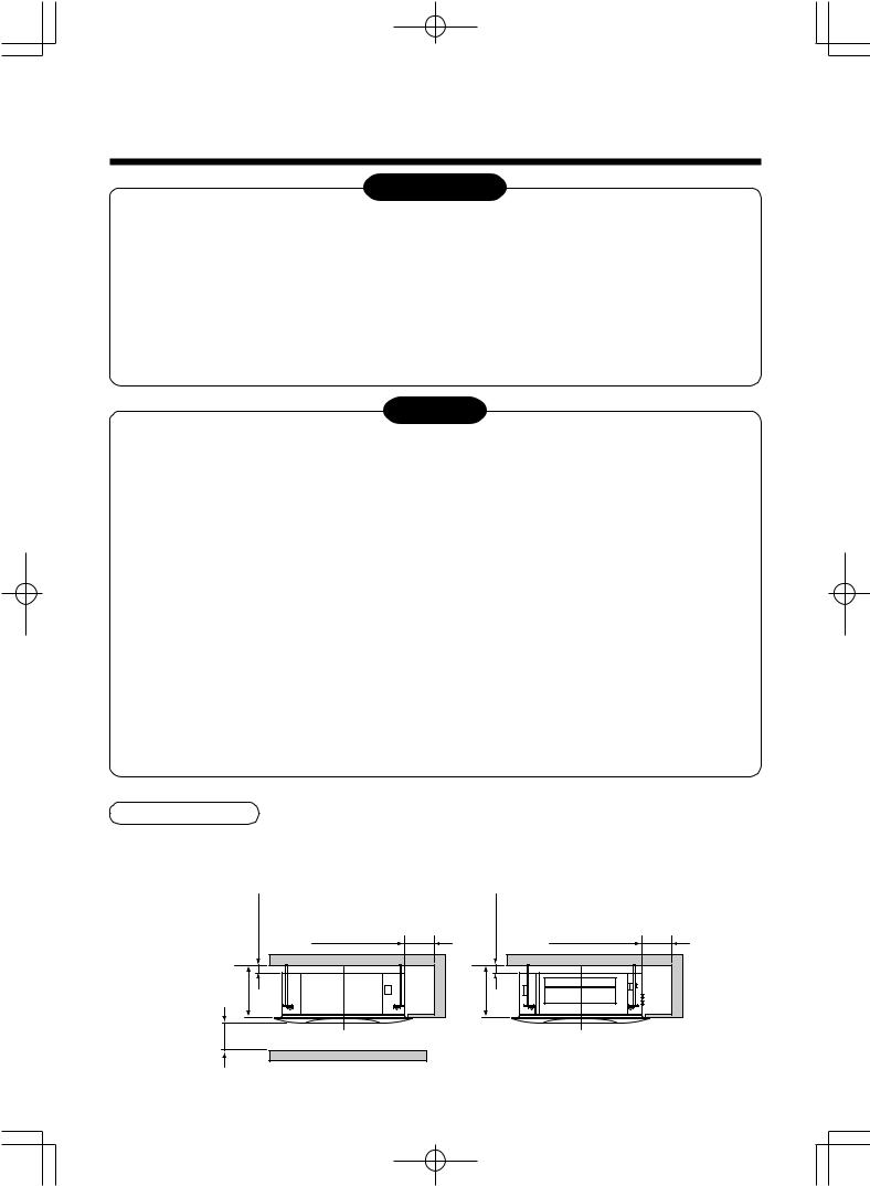
Installation space
Secure the specified space in the figure for installation and servicing.
Ensure there is sufficient space to install the unit and to perform maintenance work as and when required. Keep 15 mm or more for clearance between top plate of the indoor unit and the ceiling surface.
Installation space
283 or more
1000 or more
15 or more
1000 or more |
or more |
|
15 |
||
|
283 |
or more |
Obstacle |
|
1000 or more
4
2 SELECTION OF INSTALLATION PLACE
Selection of installation place
In case of continued operation of the indoor unit under high-humidity conditions as described below, dew may condense and water may drop.
Especially, high-humidity atmosphere (dew point temperature : 23°C or more) may generate dew inside the ceiling.
1.Unit is installed inside the ceiling with slated roof.
2.Unit is installed at a location using inside of the ceiling as fresh air intake path.
3.Kitchen
When installing a unit at such place, put insulating material (glass wool, etc.) additionally on all the positions of the indoor unit, which contact with highhumidity atmosphere.
Advice
Set a service check opening panel at right side of the unit (size: 450 × 450 mm or more) for piping, maintenance, and servicing.
Ceiling height
Model |
Possible installed |
|
RAS- |
ceiling height |
|
|
|
|
M10SMUV-E, M10SMUCV-E, |
Up to 2.7 m |
|
M13SMUV-E, M13SMUCV-E |
||
|
||
|
|
|
M16SMUV-E, M16SMUCV-E |
Up to 3.5 m |
|
|
|
When the height of the ceiling exceeds the distance of the item Standard in Table below, the hot air is difficult to reach the floor.
Therefore, it is necessary to change the setup value of the high ceiling switch.
(RAS-M16SMUV-E and M16SMUCV-E only)
When changing the setting of the ceiling height in the models, RAS-M10SMUV-E, M10SMUCV-E, M13SMUV-E and M13SMUCV-E, if it is set over
2.7 m, the hot air is difficult to reach the floor.
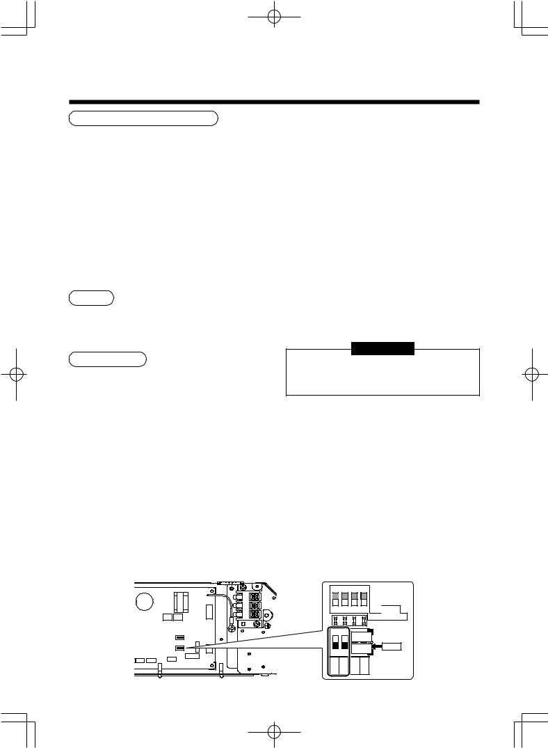
How to set the High ceiling switch
•Remove the cover of the electric parts box by taking off the mounting screws (3 positions) and pushing the hooking section. (The cover of the electric parts box remains hanged to the hinge.)
•There are the selector switches (SW02) on the P.C. board of the electric parts box.
No.1 and No.2 of the selector switches (SW02) are provided to select the height of the ceiling.
According to the ceiling height in the following table, select No.1 or No.2 of the selector switches (SW02).
REMARKS
•When using the high ceiling (1) or (2), cold air may be felt due to the temperature drop of discharge air.
Height list of ceiling possible to be installed
Model |
M10SMUV-E |
M13SMUV-E |
M16SMUV-E |
|
SW02 |
|
|
|
|
||||
RAS- |
M10SMUCV-E |
M13SMUCV-E |
M16SMUCV-E |
No.1 |
|
No.2 |
|
|
|
|
|
||
|
|
|
|
|
|
|
Standard (Factory setting) |
2.5 to 2.7 m |
2.5 to 2.7 m |
2.5 to 2.9 m |
OFF |
|
OFF |
|
|
|
|
|
|
|
High ceiling (1) |
— |
— |
2.9 to 3.2 m |
ON |
|
OFF |
|
|
|
|
|
|
|
High ceiling (2) |
— |
— |
3.2 to 3.5 m |
ON |
|
ON |
|
|
|
|
|
|
|
ON 6H
1 2 3 4
ON |
6H |
|
ON |
 SW01 TS ADJUST
ON
B
1 |
2 |
OFFA |
SW02 |
|
3 |
4 |
|
||
FAN 1 |
FAN 2 |
RESTART |
RC A/B |
|
5
 Loading...