


 Loading...
FILE NO. A00-9906
S U P P L E M E N T
SERVICE MANUAL
AIR-CONDITIONER
SPLIT TYPE
RAS-M10YKV-E, RAS-M13YKV-E / RAS-M18YAV-E RAS-M10YKCV-E, RAS-M13YKCV-E / RAS-M18YACV-E
R410A
PRINTED IN JAPAN, Nov.,1999 ToMo
CONTENTS
1. |
SPECIFICATIONS ...................................................................................... |
3 |
2. |
REFRIGERANT R410A .............................................................................. |
8 |
3. |
CONSTRUCTION VIEWS ......................................................................... |
16 |
4. |
WIRING DIAGRAM................................................................................... |
18 |
5. |
SPECIFICATIONS OF ELECTRICAL PARTS .......................................... |
21 |
6. |
REFRIGERANT CYCLE DIAGRAM ......................................................... |
22 |
7. |
CONTROL BLOCK DIAGRAM................................................................. |
25 |
8. |
OPERATION DESCRIPTION ................................................................... |
28 |
9. |
INSTALLATION PROCEDURE ................................................................ |
41 |
10. |
HOW TO DIAGNOSE THE TROUBLE ...................................................... |
49 |
11. |
HOW TO REPLACE THE MAIN PARTS ................................................... |
69 |
12. |
EXPLODED VIEWS AND PARTS LIST .................................................... |
80 |
– 2 –
|
|
|
1. SPECIFICATIONS |
|
|||
1-1. Specifications |
|
|
|
|
|
|
|
RAS-M10YKV-E, RAS-M13YKV-E / RAS-M18YAV-E |
|
|
|
||||
|
|
|
|
|
|
|
|
Unit model |
Indoor |
|
|
|
RAS-M10YKV-E, RAS-M13YKV-E |
||
|
Outdoor |
|
|
|
RAS-M18YAV-E |
||
Current limited |
|
|
|
|
— |
|
|
Cooling capacity |
|
|
|
(kW) |
5,2 |
||
Cooling capacity range |
|
|
(kW) |
1,4 – 6,2 |
|||
Heating capacity |
|
|
|
(kW) |
6,7 |
||
Heating capacity range |
|
|
(kW) |
0,9 – 8,7 |
|||
Power supply |
|
|
|
|
220 – 230 – 240V – 1Ph – 50 Hz |
||
Electric |
Indoor |
Unit model |
|
RAS-M10YKV-E |
|
RAS-M13YKV-E |
|
characteristics |
|
Running current |
(A) |
0,15 |
|
0,15 |
|
|
|
Power consumption |
(W) |
30 |
|
30 |
|
|
|
Power factor |
(%) |
87 |
|
87 |
|
|
Outdoor |
Unit model |
|
RAS-M18YAV-E |
|||
|
|
Operation mode |
|
Cooling |
|
Heating |
|
|
|
Running current |
(A) |
7,90 / 7,57 / 7,28 |
|
8,55 / 8,17 / 7,81 |
|
|
|
Power consumption |
(W) |
1660 |
|
1790 |
|
|
|
Power factor |
(%) |
95% |
|
95% |
|
|
|
Starting current |
(A) |
9,86 / 9,43 / 9,04 |
|||
COP (Cooling/Heating) |
|
|
|
3,02 / 3,62 |
|||
Operating noise |
Indoor |
Unit model |
|
RAS-M10YKV-E (Cooling / Heating) |
|
RAS-M13YKV-E (Cooling / Heating) |
|
|
|
High |
|
(dB•A) |
36 / 39 |
|
39 / 40 |
|
|
Medium |
(dB•A) |
33 / 35 |
|
35 / 35 |
|
|
|
Low |
|
(dB•A) |
30 / 30 |
|
30 / 30 |
|
Outdoor |
Unit model |
|
RAS-M18YAV-E (Cooling / Heating) |
|||
|
|
10-1 |
indoor unit operating |
(dB•A) |
42 / 45 |
||
|
|
13-1 |
indoor unit operating |
(dB•A) |
46 / 49 |
||
|
|
2 |
indoor unit operating |
(dB•A) |
46 / 49 |
||
Indoor unit |
Unit model |
|
|
|
RAS-M10YKV-E |
|
RAS-M13YKV-E |
|
Dimension |
Height |
(mm) |
265 |
|
265 |
|
|
|
Width |
|
(mm) |
790 |
|
790 |
|
|
Depth |
(mm) |
189 |
|
189 |
|
|
Net weight |
|
|
(kg) |
8 |
|
8 |
|
Fan motor output |
|
(W) |
19 |
|
19 |
|
|
Air flow rate (Cooling/Heating) |
(m3/h) |
470 / 520 |
|
520 / 560 |
||
Outdoor unit |
Unit model |
|
|
|
RAS-M18YAV-E |
||
|
Dimension |
Height |
(mm) |
550 |
|||
|
|
Width |
|
(mm) |
780 |
||
|
|
Depth |
(mm) |
270 |
|||
|
Net weight |
|
|
(kg) |
44 |
||
|
Compressor |
Motor output |
(W) |
1100 |
|||
|
|
Type |
|
|
Twin rotary type with DC-inverter variable speed control |
||
|
|
Model |
|
DA130A1F-21F |
|||
|
Fan motor output |
|
(W) |
40 |
|||
|
Air flow rate |
|
|
(m3/h) |
2060 |
||
Piping connection |
Type |
|
|
|
Flare connection |
||
|
Indoor unit |
Unit model |
|
RAS-M10YKV-E |
|
RAS-M13YKV-E |
|
|
|
Liquid side |
|
Ø6,35 |
|
Ø6,35 |
|
|
|
Gas side |
|
Ø9,52 |
|
Ø9,52 |
|
|
Outdoor unit |
Unit model |
|
RAS-M18YAV-E |
|||
|
|
A unit liquid side/gas side |
|
Ø6,35 / |
|
Ø9,52 |
|
|
|
B unit liquid side/gas side |
|
Ø6,35 / |
|
Ø9,52 |
|
|
Maximum length (per unit) |
(m) |
20 |
||||
|
Maximum length (total) |
(m) |
30 |
||||
|
Maximum chargeless length |
(m) |
30 |
||||
|
Maximum height difference |
(m) |
10 |
||||
Refrigerant |
Name of refrigerant |
|
|
R410A |
|||
|
Weight |
|
|
(kg) |
1,15 |
||
Wiring connection |
|
Power supply |
|
3 Wires : includes earth |
|||
|
|
Interconnection |
|
4 Wires : includes earth |
|||
Usable temperature range |
Indoor (Cooling/Heating) |
(°C) |
21 – 32 / 0 – 28 |
||||
|
|
Outdoor (Cooling/Heating) |
(°C) |
21 – 43 / –5 – 21 |
|||
Accessory |
Indoor unit |
Installation plate |
|
1 |
|
||
|
|
Wireless remote control |
|
1 |
|
||
|
|
Label |
|
|
2 |
|
|
|
|
Remote control holder |
|
1 |
|
||
|
|
Pan head wood screw |
|
2 (Ø3,1 x 16L) |
|||
|
|
Purifying filter |
|
1 |
|
||
|
|
Deodorizing filter |
|
1 |
|
||
|
|
Batteries |
|
2 |
|
||
|
|
Mounting screw |
|
6 (Ø4 x 25L) |
|||
|
|
Installation manual |
|
1 |
|
||
|
Outdoor unit |
Installation manual |
|
1 |
|
||
|
|
Owner's manual |
|
1 |
|
||
•For performance when each indoor unit is combined with other unit, refer to the separate table.
•The specifications may be subject to change without notice for purpose of improvement.
–3 –
RAS-M10YKCV-E, RAS-M13YKCV-E / RAS-M18YACV-E
Unit model |
Indoor |
|
|
|
RAS-M10YKCV-E, RAS-M13YKCV-E |
||
|
Outdoor |
|
|
|
RAS-M18YACV-E |
||
Cooling capacity |
|
|
|
(kW) |
5,2 |
||
Cooling capacity range |
|
|
(kW) |
1,4 – 6,2 |
|||
Power supply |
|
|
|
|
220 – 230 – 240V – 1Ph – 50 Hz |
||
Electric |
Indoor |
Unit model |
|
RAS-M10YKCV-E |
|
RAS-M13YKCV-E |
|
characteristics |
|
Running current |
(A) |
0,15 |
|
0,15 |
|
|
|
Power consumption |
(W) |
30 |
|
30 |
|
|
|
Power factor |
(%) |
87 |
|
87 |
|
|
Outdoor |
Unit model |
|
RAS-M18YACV-E |
|||
|
|
Running current |
(A) |
7,90 / 7,57 / 7,28 |
|||
|
|
Power consumption |
(W) |
1660 |
|||
|
|
Power factor |
(%) |
95% |
|||
|
|
Starting current |
(A) |
8,20 / 7,87 / 7,58 |
|||
COP |
|
|
|
|
3,02 |
||
Operating noise |
Indoor |
Unit model |
|
RAS-M10YKCV-E |
|
RAS-M13YKCV-E |
|
|
|
High |
|
(dB•A) |
36 |
|
39 |
|
|
Medium |
(dB•A) |
33 |
|
35 |
|
|
|
Low |
|
(dB•A) |
30 |
|
30 |
|
Outdoor |
Unit model |
|
RAS-M18YACV-E |
|||
|
|
10-1 |
indoor unit operating |
(dB•A) |
42 |
||
|
|
13-1 |
indoor unit operating |
(dB•A) |
46 |
||
|
|
2 |
indoor unit operating |
(dB•A) |
46 |
||
Indoor unit |
Unit model |
|
|
|
RAS-M10YKCV-E |
|
RAS-M13YKCV-E |
|
Dimension |
Height |
(mm) |
265 |
|
265 |
|
|
|
Width |
|
(mm) |
790 |
|
790 |
|
|
Depth |
(mm) |
189 |
|
189 |
|
|
Net weight |
|
|
(kg) |
8 |
|
8 |
|
Fan motor output |
|
(W) |
19 |
|
19 |
|
|
Air flow rate |
|
|
(m3/h) |
470 |
|
520 |
Outdoor unit |
Unit model |
|
|
|
RAS-M18YACV-E |
||
|
Dimension |
Height |
(mm) |
550 |
|||
|
|
Width |
|
(mm) |
780 |
||
|
|
Depth |
(mm) |
270 |
|||
|
Net weight |
|
|
(kg) |
42 |
||
|
Compressor |
Motor output |
(W) |
1100 |
|||
|
|
Type |
|
|
Twin rotary type with DC-inverter variable speed control |
||
|
|
Model |
|
DA130A1F-21F |
|||
|
Fan motor output |
|
(W) |
40 |
|||
|
Air flow rate |
|
|
(m3/h) |
2060 |
||
Piping connection |
Type |
|
|
|
Flare connection |
||
|
Indoor unit |
Unit model |
|
RAS-M10YKCV-E |
|
RAS-M13YKCV-E |
|
|
|
Liquid side |
|
Ø6,35 |
|
Ø6,35 |
|
|
|
Gas side |
|
Ø9,52 |
|
Ø9,52 |
|
|
Outdoor unit |
Unit model |
|
RAS-M18YACV-E |
|||
|
|
A unit liquid side/gas side |
|
Ø6,35 / |
|
Ø9,52 |
|
|
|
B unit liquid side/gas side |
|
Ø6,35 / |
|
Ø9,52 |
|
|
Maximum length (per unit) |
(m) |
20 |
||||
|
Maximum length (total) |
(m) |
30 |
||||
|
Maximum chargeless length |
(m) |
30 |
||||
|
Maximum height difference |
(m) |
10 |
||||
Refrigerant |
Name of refrigerant |
|
|
R410A |
|||
|
Weight |
|
|
(kg) |
1,15 |
||
Wiring connection |
|
Power supply |
|
3 Wires : includes earth |
|||
|
|
Interconnection |
|
4 Wires : includes earth |
|||
Usable temperature range |
Indoor |
(°C) |
21 – 32 |
||||
|
|
Outdoor |
(°C) |
21 – 43 |
|||
Accessory |
Indoor unit |
Installation plate |
|
1 |
|
||
|
|
Wireless remote control |
|
1 |
|
||
|
|
Label |
|
|
2 |
|
|
|
|
Remote control holder |
|
1 |
|
||
|
|
Pan head wood screw |
|
2 (Ø3,1 x 16L) |
|||
|
|
Purifying filter |
|
1 |
|
||
|
|
Deodorizing filter |
|
1 |
|
||
|
|
Batteries |
|
2 |
|
||
|
|
Mounting screw |
|
6 (Ø4 x 25L) |
|||
|
|
Installation manual |
|
1 |
|
||
|
Outdoor unit |
Installation manual |
|
1 |
|
||
|
|
Owner's manual |
|
1 |
|
||
•For performance when each indoor unit is combined with other unit, refer to the separate table.
•The specifications may be subject to change without notice for purpose of improvement.
–4 –
1-2. Specifications of Performance When Each Indoor Unit is Combined with Other Unit
<Cooling>
Volts |
Operation |
Operating |
Unit capacity |
Cooling |
Running |
Power |
Outdoor |
|||
indoor unit |
(kW) |
capacity |
current |
consumption |
operating noise |
|||||
|
status |
|
|
|
|
|
|
|
|
|
V |
A |
B |
A |
B |
kW |
A |
W |
dB |
||
|
||||||||||
|
|
10 |
— |
2,7 |
— |
2,7 |
4,13 |
770 |
42 |
|
|
1 unit |
|
|
|
|
(1,1 to 3,2) |
(1,65 to 4,99) |
(255 to 930) |
|
|
|
13 |
— |
3,7 |
— |
3,7 |
6,58 |
1240 |
46 |
||
|
|
|||||||||
220 |
|
|
|
|
|
(1,1 to 4,2) |
(1,65 to 7,25) |
(255 to 1430) |
|
|
|
10 |
10 |
2,55 |
2,55 |
5,1 |
8,14 |
1700 |
46 |
||
|
|
|||||||||
|
2 units |
|
|
|
|
(1,4 to 6,1) |
(1,68 to 10,29) |
(260 to 2150) |
|
|
|
13 |
10 |
3,01 |
2,19 |
5,2 |
8,20 |
1720 |
46 |
||
|
|
|||||||||
|
|
|
|
|
|
(1,4 to 6,2) |
(1,68 to 10,38) |
(260 to 2170) |
|
|
|
|
10 |
— |
2,7 |
— |
2,7 |
3,95 |
770 |
42 |
|
|
1 unit |
|
|
|
|
(1,1 to 3,2) |
(1,59 to 4,78) |
(255 to 930) |
|
|
|
13 |
— |
3,7 |
— |
3,7 |
6,30 |
1240 |
46 |
||
|
|
|||||||||
230 |
|
|
|
|
|
(1,1 to 4,2) |
(1,59 to 6,94) |
(255 to 1430) |
|
|
|
10 |
10 |
2,55 |
2,55 |
5,1 |
7,78 |
1700 |
46 |
||
|
|
|||||||||
|
2 units |
|
|
|
|
(1,4 to 6,1) |
(1,62 to 9,84) |
(260 to 2150) |
|
|
|
13 |
10 |
3,01 |
2,19 |
5,2 |
7,87 |
1720 |
46 |
||
|
|
|||||||||
|
|
|
|
|
|
(1,4 to 6.2) |
(1,62 to 9,93) |
(260 to 2170) |
|
|
|
|
10 |
— |
2,7 |
— |
2,7 |
3,79 |
770 |
42 |
|
|
1 unit |
|
|
|
|
(1,1 to 3,2) |
(1,52 to 4,58) |
(255 to 930) |
|
|
|
13 |
— |
3,7 |
— |
3,7 |
6,03 |
1240 |
46 |
||
|
|
|||||||||
240 |
|
|
|
|
|
(1,1 to 4,2) |
(1,52 to 6,65) |
(255 to 1430) |
|
|
|
10 |
10 |
2,55 |
2,55 |
5,1 |
7,46 |
1700 |
46 |
||
|
|
|||||||||
|
2 units |
|
|
|
|
(1,4 to 6,1) |
(1,55 to 9,43) |
(260 to 2150) |
|
|
|
13 |
10 |
3,01 |
2,19 |
5,2 |
7,58 |
1720 |
46 |
||
|
|
|||||||||
|
|
|
|
|
|
(1,4 to 6,2) |
(1,55 to 9,52) |
(260 to 2170) |
|
|
<Heating>
Volts |
Operation |
Operating |
Unit capacity |
|
Heating |
|
Running |
|
Power |
Outdoor |
||
indoor unit |
(kW) |
|
capacity |
|
current |
|
consumption |
operating noise |
||||
|
status |
|
|
|
|
|
|
|
|
|
|
|
V |
A |
B |
A |
B |
|
kW |
|
A |
|
W |
dB |
|
|
|
|
|
|||||||||
|
|
10 |
— |
4,0 |
— |
|
4,0 |
|
6,94 |
|
1450 |
45 |
|
1 unit |
|
|
|
|
|
(0,7 to 5,2) |
|
(1,10 to 8,13) |
|
(170 to 1700) |
|
|
13 |
— |
5,0 |
— |
|
5,0 |
|
9,86 |
|
2060 |
49 |
|
|
|
|
|
|
||||||||
220 |
|
|
|
|
|
|
(0,7 to 6,5) |
|
(1,10 to 12,11) |
|
(170 to 2530) |
|
|
10 |
10 |
3,2 |
3,2 |
|
6,4 |
|
8,47 |
|
1770 |
49 |
|
|
|
|
|
|
||||||||
|
2 units |
|
|
|
|
|
(0,9 to 8,3) |
|
(1,10 to 11,43) |
|
(170 to 2390) |
|
|
13 |
10 |
3,72 |
2,98 |
|
6,7 |
|
8,85 |
|
1850 |
49 |
|
|
|
|
|
|
||||||||
|
|
|
|
|
|
|
(0,9 to 8,7) |
|
(1,10 to 11,72) |
|
(170 to 2450) |
|
|
|
10 |
— |
4,0 |
— |
|
4,0 |
|
6,64 |
|
1450 |
45 |
|
1 unit |
|
|
|
|
|
(0,7 to 5,2) |
|
(1,06 to 7,78) |
|
(170 to 1700) |
|
|
13 |
— |
5,0 |
— |
|
5,0 |
|
9,43 |
|
2060 |
49 |
|
|
|
|
|
|
||||||||
230 |
|
|
|
|
|
|
(0,7 to 6,5) |
|
(1,06 to 11,58) |
|
(170 to 2530) |
|
|
10 |
10 |
3,2 |
3,2 |
|
6,4 |
|
8,10 |
|
1770 |
49 |
|
|
|
|
|
|
||||||||
|
2 units |
|
|
|
|
|
(0,9 to 8,3) |
|
(1,06 to 10,94) |
|
(170 to 2390) |
|
|
13 |
10 |
3,72 |
2,98 |
|
6,7 |
|
8,47 |
|
1850 |
49 |
|
|
|
|
|
|
||||||||
|
|
|
|
|
|
|
(0,9 to 8,7) |
|
(1,06 to 11,21) |
|
(170 to 2450) |
|
|
|
10 |
— |
4,0 |
— |
|
4,0 |
|
6,36 |
|
1450 |
45 |
|
1 unit |
|
|
|
|
|
(0,7 to 5,2) |
|
(1,01 to 7,46) |
|
(170 to 1700) |
|
|
13 |
— |
5,0 |
— |
|
5,0 |
|
9,04 |
|
2060 |
49 |
|
|
|
|
|
|
||||||||
240 |
|
|
|
|
|
|
(0,7 to 6,5) |
|
(1,01 to 11,10) |
|
(170 to 2530) |
|
|
10 |
10 |
3,2 |
3,2 |
|
6,4 |
|
7,76 |
|
1770 |
49 |
|
|
|
|
|
|
||||||||
|
2 units |
|
|
|
|
|
(0,9 to 8,3) |
|
(1,01 to 10,48) |
|
(170 to 2390) |
|
|
13 |
10 |
3,72 |
2,98 |
|
6,7 |
|
8,11 |
|
1850 |
49 |
|
|
|
|
|
|
||||||||
|
|
|
|
|
|
|
(0,9 to 8,7) |
|
(1,01 to 10,75) |
|
(170 to 2450) |
|
• The above specification values are those under the conditions |
|
|
|
|
||||||||
Cooling indoor : DB/WB=27/19°C |
|
Cooling outdoor : DB=35°C |
|
|
||||||||
Heating indoor : DB=20°C |
|
|
Heating outdoor : DB/WB=7/6°C |
|
|
|||||||
– 5 –

1-2-1. Operation Characteristic Curve
<Cooling>
|
10 |
|
|
|
|
|
|
|
|
|
|
|
|
|
|
|
|
|
|
|
|
|
|
|
|
|
|
|
|
|
9 |
|
|
|
|
|
|
|
|
|
|
|
|
|
|
8 |
|
|
|
|
|
|
|
|
|
|
|
|
|
|
7 |
|
|
|
|
|
|
|
|
|
|
|
|
|
(A) |
6 |
|
|
|
|
|
|
|
|
|
|
|
|
|
|
|
|
|
|
|
|
|
|
|
|
|
|
|
|
Current |
5 |
|
|
|
|
|
|
|
|
|
|
|
|
|
|
|
|
|
|
|
|
|
|
|
|
|
|
|
|
|
4 |
|
|
|
|
|
|
|
|
|
|
|
|
|
|
|
|
|
|
|
|
|
|
|
|
|
|
||
|
3 |
|
|
|
|
• Conditions |
|
|
|
|
|
|
||
|
|
|
|
|
|
Indoor : DB 27˚C/WB 19˚C |
|
|
|
|||||
|
2 |
|
|
|
|
Outdoor : DB 35˚C |
|
|
|
|
|
|||
|
|
|
|
|
Air flow : High |
|
|
|
|
|
|
|||
|
|
|
|
|
|
|
|
|
|
|
|
|||
|
1 |
|
|
|
|
Pipe length : 5m x 2 |
|
|
|
|
||||
|
|
|
|
|
2 units operating |
|
|
|
|
|
||||
|
|
|
|
|
|
230V |
|
|
|
|
|
|
|
|
|
0 |
|
|
|
|
|
|
|
|
|
|
|
|
|
|
|
10 |
20 |
30 |
40 |
50 |
60 |
70 |
80 |
90 |
100 |
|||
|
0 |
|||||||||||||
<Heating>
|
12 |
|
|
|
|
|
|
|
|
|
|
|
|
|
|
|
|
|
|
|
|
|
|
|
10 |
|
|
|
|
|
|
|
|
|
|
|
8 |
|
|
|
|
|
|
|
|
|
|
(A) |
|
|
|
|
|
|
|
|
|
|
|
Current |
6 |
|
|
|
|
|
|
|
|
|
|
|
|
|
|
|
|
|
|
|
|
|
|
|
4 |
|
|
|
|
|
|
|
|
|
|
|
|
|
|
• Conditions |
|
|
|
|
|
||
|
|
|
|
|
|
|
|
|
|
||
|
|
|
|
|
Indoor : DB 20˚C |
|
|
|
|
||
|
|
|
|
|
Outdoor : DB 7˚C/WB 6˚C |
|
|
|
|||
|
2 |
|
|
|
Air flow : High |
|
|
|
|
||
|
|
|
|
|
Pipe length : 5m x 2 |
|
|
|
|
||
|
|
|
|
|
2 units operating |
|
|
|
|
||
|
|
|
|
|
230V |
|
|
|
|
|
|
|
0 |
|
|
|
|
|
|
|
|
|
|
|
|
20 |
40 |
60 |
80 |
100 |
120 |
140 |
|||
|
0 |
||||||||||
Compressor speed (rps) |
Compressor speed (rps) |
1-2-2. Cooling Capacity Variation Ratio According to Temperature
Capacity ratio (%)
115 |
|
|
|
|
|
|
|
|
|
|
|
|
|
|
|
|
|
• Conditions |
|
|
|
|
|
110 |
|
Indoor : DB27˚C |
|
|
|
|
|
|
Outdoor : DB35˚C |
|
|
|
|
||
|
|
Indoor air flow : High |
|
|
|
|
|
|
|
Pipe length 5m×2 |
|
|
|
|
|
105 |
|
2 units operating |
|
|
|
|
|
|
|
|
|
|
|
|
|
100 |
|
|
|
|
|
|
|
95 |
|
|
|
|
|
|
|
90 |
|
|
|
|
|
|
|
85 |
|
|
|
|
|
|
|
0 |
|
|
|
|
|
|
|
|
16 |
18 |
20 |
22 |
24 |
||
14 |
|||||||
Indoor air wet bulb temp. (˚C)
Capacity ratio (%)
105 |
|
|
|
|
Current Limited Start |
||
100 |
|
||
|
|
|
|
95 |
|
|
|
90 |
|
|
|
85 |
|
|
|
80 |
|
|
|
75 |
|
|
|
70 |
|
|
|
65 |
|
|
|
60 |
|
• Conditions |
|
|
Indoor : DB27˚C/WB19˚C |
|
|
|
|
Indoor air flow : High |
|
55 |
|
Pipe length 5m×2 |
|
|
|
2 units operating |
|
50
32 33 34 35 36 37 38 39 40 41 42 43
Outdoor temp. (˚C)
* Capacity ratio : 100% = 5,2 kW
– 6 –
1-3. |
Electrical Data |
|
|
|
|
|
|
|
|
|
|
|||
<Cooling> |
|
|
|
|
|
|
|
|
|
|
|
|||
|
|
|
|
|
|
|
|
|
|
|
|
|
|
|
Combination |
|
|
|
System |
|
|
|
Compressor |
Fan motor FLA |
|||||
|
|
|
|
|
|
|
|
|||||||
of indoor unit |
|
|
Voltage range |
|
Power supply |
|||||||||
|
|
|
|
|
|
|
||||||||
operation |
|
|
|
|
|
|
|
|||||||
|
Volts- |
|
|
|
|
|
|
|
|
|
|
|||
|
|
|
Hz |
|
|
|
|
|
MOCP |
|
|
|
|
|
|
|
|
Ph. |
Min. |
Max. |
|
MCA |
ICF |
MSC |
RLA |
Indoor |
Outdoor |
||
A |
|
B |
|
|
(Amps) |
|||||||||
|
|
|
|
|
|
|
|
|
|
|
|
|||
|
|
|
|
|
|
|
|
|
|
|
|
|
|
|
10 |
|
— |
|
|
|
|
|
5,81 |
5,81 |
15 |
4,13 |
4,13 |
0,15 x 1=0,15 |
0,50 |
|
|
|
|
|
|
|
|
|
|
|
|
|
|
|
13 |
|
— |
50 |
230–1 |
198 |
264 |
|
8,51 |
8,51 |
15 |
6,29 |
6,29 |
0,15 x 1=0,15 |
0,50 |
|
|
|
|
|
|
|
|
|
|
|
||||
10 |
|
10 |
|
12,10 |
12,10 |
15 |
9,04 |
9,04 |
0,15 x 2=0,30 |
0,50 |
||||
|
|
|
|
|
|
|||||||||
|
|
|
|
|
|
|
|
|
|
|
|
|
|
|
13 |
|
10 |
|
|
|
|
|
12,21 |
12,21 |
15 |
9,13 |
9,13 |
0,15 x 2=0,30 |
0,50 |
|
|
|
|
|
|
|
|
|
|
|
|
|
|
|
<Heating> |
|
|
|
|
|
|
|
|
|
|
|
|||
|
|
|
|
|
|
|
|
|
|
|
|
|
|
|
Combination |
|
|
|
System |
|
|
|
Compressor |
Fan motor FLA |
|||||
|
|
|
|
|
|
|
|
|||||||
of indoor unit |
|
|
Voltage range |
|
Power supply |
|||||||||
|
|
|
|
|
|
|
||||||||
operation |
|
|
|
|
|
|
|
|||||||
|
Volts- |
|
|
|
|
|
|
|
|
|
|
|||
|
|
|
Hz |
|
|
|
|
|
MOCP |
|
|
|
|
|
|
|
|
Ph. |
Min. |
Max. |
|
MCA |
ICF |
MSC |
RLA |
Indoor |
Outdoor |
||
A |
|
B |
|
|
(Amps) |
|||||||||
|
|
|
|
|
|
|
|
|
|
|
|
|||
|
|
|
|
|
|
|
|
|
|
|
|
|
|
|
10 |
|
— |
|
|
|
|
|
9,56 |
9,56 |
15 |
7,13 |
7,13 |
0,15 x 1=0,15 |
0,50 |
|
|
|
|
|
|
|
|
|
|
|
|
|
|
|
13 |
|
— |
50 |
230–1 |
198 |
264 |
|
14,31 |
14,31 |
15 |
10,93 |
10,93 |
0,15 x 1=0,15 |
0,50 |
|
|
|
|
|
|
|
|
|
|
|
||||
10 |
|
10 |
|
13,47 |
13,47 |
15 |
10,14 |
10,14 |
0,15 x 2=0,30 |
0,50 |
||||
|
|
|
|
|
|
|||||||||
|
|
|
|
|
|
|
|
|
|
|
|
|
|
|
13 |
|
10 |
|
|
|
|
|
13,81 |
13,81 |
15 |
10,41 |
10,41 |
0,15 x 2=0,30 |
0,50 |
|
|
|
|
|
|
|
|
|
|
|
|
|
|
|
NOTE :
Model of Indoor unit :
10 : RAS-M10YKV-E, RAS-M10YKCV-E 13 : RAS-M13YKV-E, RAS-M13YKCV-E
MCA |
: Minimum Circuit Amps. |
ICF |
: Maximum Instantaneous Current Flow |
|
(Equivalent to MCA in case of inverter air conditioner) |
MOCP : Maximum Overcurrent Protection (Fuse only)
MSC |
: Maximum Starting Current |
FLA |
: Full Load Amps. |
RLA |
: Rated Load Amps. RLA under conditions on the right. |
<Cooling>
|
|
DB |
WB |
|
|
|
|
Indoor temp. |
°C |
27 |
19 |
|
|
|
|
Outdoor temp. |
°C |
35 |
— |
|
|
|
|
<Heating>
|
|
DB |
WB |
|
|
|
|
Indoor temp. |
°C |
20 |
— |
|
|
|
|
Outdoor temp. |
°C |
7 |
6 |
|
|
|
|
– 7 –
2. REFRIGERANT R410A
This air conditioner adopts the new refrigerant HFC (R410A) which does not damage the ozone layer.
The working pressure of the new refrigerant R410A is 1,6 times higher than conventional refrigerant (R22). The refrigerating oil is also changed in accordance with change of refrigerant, so be careful that water, dust, and existing refrigerant or refrigerating oil are not entered in the refrigerant cycle of the air conditioner using the new refrigerant during installation work or servicing time.
The next section describes the precautions for air conditioner using the new refrigerant. Conforming to contents of the next section together with the general cautions included in this manual, perform the correct and safe work.
2-1. Safety During Installation/Servicing
As R410A’s pressure is about 1,6 times higher than that of R22, improper installation/servicing may cause a serious trouble. By using tools and materials exclusive for R410A, it is necessary to carry out installation/servicing safely while taking the following precautions into consideration.
(1)Never use refrigerant other than R410A in an air conditioner which is designed to operate with R410A.
If other refrigerant than R410A is mixed, pressure in the refrigeration cycle becomes abnormally high, and it may cause personal injury, etc. by a rupture.
(2)Confirm the used refrigerant name, and use tools and materials exclusive for the refrigerant R410A.
The refrigerant name R410A is indicated on the visible place of the outdoor unit of the air conditioner using R410A as refrigerant. To prevent mischarging, the diameter of the service port differs from that of R22.
(3)If a refrigeration gas leakage occurs during installation/servicing, be sure to ventilate fully.
If the refrigerant gas comes into contact with fire, a poisonous gas may occur.
(4)When installing or removing an air conditioner, do not allow air or moisture to remain in the refrigeration cycle. Otherwise, pressure in the refrigeration cycle may become abnormally high so that a rupture or personal injury may be caused.
(5)After completion of installation work, check to make sure that there is no refrigeration gas leakage.
If the refrigerant gas leaks into the room, coming into contact with fire in the fan-driven heater, space heater, etc., a poisonous gas may occur.
(6)When an air conditioning system charged with a large volume of refrigerant is installed in a small room, it is necessary to exercise care so that, even when refrigerant leaks, its concentration does not exceed the marginal level.
If the refrigerant gas leakage occurs and its concentration exceeds the marginal level, an oxygen starvation accident may result.
(7)Be sure to carry out installation or removal according to the installation manual.
Improper installation may cause refrigeration trouble, water leakage, electric shock, fire, etc.
(8)Unauthorized modifications to the air conditioner may be dangerous. If a breakdown occurs please call a qualified air conditioner technician or electrician.
Improper repair’s may result in water leakage, electric shock and fire, etc.
2-2. Refrigerant Piping Installation
2-2-1. Piping Materials and Joints Used
For the refrigerant piping installation, copper pipes and joints are mainly used. Copper pipes and joints suitable for the refrigerant must be chosen and installed. Furthermore, it is necessary to use clean copper pipes and joints whose interior surfaces are less affected by contaminants.
(1)Copper Pipes
It is necessary to use seamless copper pipes which are made of either copper or copper alloy and it is desirable that the amount of residual oil is less than 40 mg/10 m. Do not use copper pipes having a collapsed, deformed or discolored portion (especially on the interior surface). Otherwise, the expansion valve or capillary tube may become blocked with contaminants.
As an air conditioner using R410A incurs pressure higher than when using R22, it is necessary to choose adequate materials.
Thicknesses of copper pipes used with R410A are as shown in Table 2-2-1. Never use copper pipes thinner than 0,8 mm even when it is available on the market.
– 8 –

Table 2-2-1 Thicknesses of annealed copper pipes
|
|
|
Thickness (mm) |
|
|
|
|
Nominal diameter |
Outer diameter (mm) |
R410A |
R22 |
|
|
|
|
1/4 |
6,35 |
0,80 |
0,80 |
|
|
|
|
3/8 |
9,52 |
0,80 |
0,80 |
|
|
|
|
1/2 |
12,70 |
0,80 |
0,80 |
|
|
|
|
5/8 |
15,88 |
1,00 |
1,00 |
|
|
|
|
(2)Joints
For copper pipes, flare joints or socket joints are used. Prior to use, be sure to remove all contaminants.
a)Flare Joints
Flare joints used to connect the copper pipes cannot be used for pipings whose outer diameter exceeds 20 mm. In such a case, socket joints can be used.
Sizes of flare pipe ends, flare joint ends and flare nuts are as shown in Tables 2-2-3 ~ 2-2- 6 below.
b)Socket Joints
Socket joints are such that they are brazed for connections, and used mainly for thick pipings whose diameter is larger than 20 mm. Thicknesses of socket joints are as shown in Table 2-2-2.
Table 2-2-2 Minimum thicknesses of socket joints
Nominal diameter |
Reference outer diameter of |
Minimum joint thickness |
|
copper pipe jointed (mm) |
(mm) |
||
|
|||
|
|
|
|
1/4 |
6,35 |
0,50 |
|
|
|
|
|
3/8 |
9,52 |
0,60 |
|
|
|
|
|
1/2 |
12,70 |
0,70 |
|
|
|
|
|
5/8 |
15,88 |
0,80 |
|
|
|
|
2-2-2. Processing of Piping Materials
When performing the refrigerant piping installation, care should be taken to ensure that water or dust does not enter the pipe interior, that no other oil other than lubricating oils used in the installed air conditioner is used, and that refrigerant does not leak. When using lubricating oils in the piping processing, use such lubricating oils whose water content has been removed. When stored, be sure to seal the container with an airtight cap or any other cover.
(1)Flare Processing Procedures and Precautions
a)Cutting the Pipe
By means of a pipe cutter, slowly cut the pipe so that it is not deformed.
b)Removing Burrs and Chips
If the flared section has chips or burrs, refrigerant leakage may occur. Carefully remove all burrs and clean the cut surface before installation.
– 9 –
c)Insertion of Flare Nut
d)Flare Processing
Make certain that a clamp bar and copper pipe have been cleaned.
By means of the clamp bar, perform the flare processing correctly.
Use either a flare tool for R410A or conventional flare tool.
Flare processing dimensions differ according to the type of flare tool. When using a conventional flare tool, be sure to secure “dimension A” by using a gauge for size adjustment.
ØD |
A |
Fig. 2-2-1 Flare processing dimensions
Table 2-2-3 Dimensions related to flare processing for R410A
|
|
Outer |
|
|
|
|
|
|
|
|
A (mm) |
|
|
|
|
Nominal |
|
|
Thickness |
|
|
|
|
|
|
|
|
|
|
||
|
|
|
|
|
|
|
|
|
|
|
|||||
|
diameter |
|
|
Flare tool for |
|
Conventional flare tool |
|||||||||
diameter |
|
|
|
(mm) |
|
|
|||||||||
|
(mm) |
|
|
|
|
|
|
|
|
|
|||||
|
|
|
|
|
|
R410A clutch type |
|
Clutch type |
Wing nut type |
||||||
|
|
|
|
|
|
|
|
||||||||
|
|
|
|
|
|
|
|
|
|
|
|||||
|
|
|
|
|
|
|
|
|
|
|
|
|
|||
1/4 |
|
6,35 |
|
0,8 |
|
0 to 0,5 |
|
|
1,0 to 1,5 |
|
|
1,5 to 2,0 |
|||
|
|
|
|
|
|
|
|
|
|
|
|
|
|||
3/8 |
|
9,52 |
|
0,8 |
|
0 to 0,5 |
|
|
1,0 to 1,5 |
|
|
1,5 to 2,0 |
|||
|
|
|
|
|
|
|
|
|
|
|
|
|
|||
1/2 |
|
12,70 |
|
0,8 |
|
0 to 0,5 |
|
|
1,0 to 1,5 |
|
|
2,0 to 2,5 |
|||
|
|
|
|
|
|
|
|
|
|
|
|
|
|||
5/8 |
|
15,88 |
|
1,0 |
|
0 to 0,5 |
|
|
1,0 to 1,5 |
|
|
2,0 to 2,5 |
|||
|
|
|
|
|
|
|
|
|
|||||||
|
|
Table 2-2-4 Dimensions related to flare processing for R22 |
|
|
|
||||||||||
|
|
|
|
|
|
|
|
|
|
|
|
|
|
|
|
|
|
Outer |
|
|
|
|
|
|
|
|
A (mm) |
|
|
|
|
Nominal |
|
|
Thickness |
|
|
|
|
|
|
|
|
|
|
||
|
|
|
|
|
|
|
|
|
|
|
|||||
|
diameter |
|
|
Flare tool for |
|
Conventional flare tool |
|||||||||
diameter |
|
|
|
(mm) |
|
|
|||||||||
|
(mm) |
|
|
|
|
|
|
|
|
|
|||||
|
|
|
|
|
|
R22 clutch type |
|
Clutch type |
Wing nut type |
||||||
|
|
|
|
|
|
|
|
||||||||
|
|
|
|
|
|
|
|
|
|
|
|||||
|
|
|
|
|
|
|
|
|
|
|
|
|
|||
1/4 |
|
6,35 |
|
0,8 |
|
0 to 0,5 |
|
|
0,5 to 1,0 |
|
|
1,0 to 1,5 |
|||
|
|
|
|
|
|
|
|
|
|
|
|
|
|||
3/8 |
|
9,52 |
|
0,8 |
|
0 to 0,5 |
|
|
0,5 to 1,0 |
|
|
1,0 to 1,5 |
|||
|
|
|
|
|
|
|
|
|
|
|
|
|
|||
1/2 |
|
12,70 |
|
0,8 |
|
0 to 0,5 |
|
|
0,5 to 1,0 |
|
|
1,5 to 2,0 |
|||
|
|
|
|
|
|
|
|
|
|
|
|
|
|||
5/8 |
|
15,88 |
|
1,0 |
|
0 to 0,5 |
|
|
0,5 to 1,0 |
|
|
1,5 to 2,0 |
|||
|
|
|
|
|
|
|
|
|
|||||||
|
|
Table 2-2-5 Flare and flare nut dimensions for R410A |
|
|
|
||||||||||
|
|
|
|
|
|
|
|
|
|
|
|
|
|
|
|
Nominal |
Outer diameter |
|
Thickness |
|
|
Dimension (mm) |
|
|
Flare nut |
||||||
|
|
|
|
|
|
|
|
|
width |
||||||
diameter |
(mm) |
|
(mm) |
A |
|
B |
|
C |
|
D |
|
(mm) |
|||
|
|
|
|
|
|
|
|
|
|
|
|||||
|
|
|
|
|
|
|
|
|
|
|
|
|
|
|
|
1/4 |
|
6,35 |
|
|
0,8 |
|
9,1 |
|
9,2 |
6,5 |
|
13 |
|
17 |
|
|
|
|
|
|
|
|
|
|
|
|
|
|
|
|
|
3/8 |
|
9,52 |
|
|
0,8 |
|
13,2 |
|
13,5 |
9,7 |
|
20 |
|
22 |
|
|
|
|
|
|
|
|
|
|
|
|
|
|
|
|
|
1/2 |
|
12,70 |
|
|
0,8 |
|
16,6 |
|
16,0 |
12,9 |
|
23 |
|
26 |
|
|
|
|
|
|
|
|
|
|
|
|
|
|
|
|
|
5/8 |
|
15,88 |
|
|
1,0 |
|
19,7 |
|
19,0 |
16,0 |
|
25 |
|
29 |
|
|
|
|
|
|
|
|
|
|
|
|
|
|
|
|
|
– 10 –
Table 2-2-6 Flare and flare nut dimensions for R22
Nominal |
Outer diameter |
Thickness |
|
|
|
Dimension (mm) |
|
|
|
|
|
Flare nut |
||||||||||||||||||
|
|
|
|
|
|
|
|
|
|
|
|
|
|
|
width |
|||||||||||||||
diameter |
(mm) |
|
|
|
(mm) |
|
|
|
|
|
|
A |
B |
C |
|
|
|
|
D |
(mm) |
||||||||||
|
|
|
|
|
|
|
|
|
|
|
|
|
|
|
|
|
|
|
|
|||||||||||
|
|
|
|
|
|
|
|
|
|
|
|
|
|
|
|
|
|
|
|
|
|
|
|
|
|
|
|
|
|
|
1/4 |
6,35 |
0,8 |
|
|
|
|
|
|
|
9,0 |
|
9,2 |
6,5 |
|
|
|
13 |
17 |
||||||||||||
|
|
|
|
|
|
|
|
|
|
|
|
|
|
|
|
|
|
|
|
|
|
|
|
|
|
|
|
|
|
|
3/8 |
9,52 |
0,8 |
|
|
|
|
|
|
|
13,0 |
|
13,5 |
9,7 |
|
|
|
20 |
22 |
||||||||||||
|
|
|
|
|
|
|
|
|
|
|
|
|
|
|
|
|
|
|
|
|
|
|
|
|
|
|
|
|
|
|
1/2 |
12,70 |
0,8 |
|
|
|
|
|
|
|
16,2 |
|
16,0 |
12,9 |
|
|
|
20 |
24 |
||||||||||||
|
|
|
|
|
|
|
|
|
|
|
|
|
|
|
|
|
|
|
|
|
|
|
|
|
|
|
|
|
|
|
5/8 |
15,88 |
1,0 |
|
|
|
|
|
|
|
19,4 |
|
19,0 |
16,0 |
|
|
|
23 |
27 |
||||||||||||
|
|
|
|
|
|
|
|
|
|
|
|
|
|
|
|
|
|
|
|
|
|
|
|
|
|
|
|
|
|
|
3/4 |
19,05 |
1,0 |
|
|
|
|
|
|
|
23,3 |
|
24,0 |
19,2 |
|
|
|
34 |
36 |
||||||||||||
|
|
|
|
|
|
|
|
|
|
|
|
|
|
|
|
|
|
|
|
|
|
|
|
|
|
|
|
|
|
|
|
|
|
46˚ |
|
|
|
|
|
|
|
|
|
|
|
|
|
|
|
|
|
|
|
|
|
||||||
|
|
|
~ |
|
|
|
|
|
|
|
|
|
|
|
|
|
|
|
|
|
|
|
|
|
|
|
|
|
|
|
|
|
45˚ |
|
|
|
|
|
|
|
|
|
|
|
|
|
|
|
|
|
|
|
|
|
|||||||
|
|
|
|
|
|
|
|
|
|
|
|
|
|
|
|
|
|
|
|
|
|
|
|
|
|
|
|
|
|
|
|
|
|
|
|
|
|
|
|
|
|
|
|
|
|
|
|
|
|
|
|
|
|
|
|
|
|
|
|
|
|
|
|
|
|
|
|
|
B |
|
A |
|
|
|
|
|
|
|
|
|
|
C |
|
|
D |
|
|
|||||
|
|
|
|
|
|
|
|
|
|
|
||||||||||||||||||||
|
|
|
|
|
|
|
|
|
|
|
|
|
|
|
|
|
|
|
|
|
|
|
|
|
|
|
|
|
|
|
|
|
|
|
|
|
|
|
|
|
|
|
|
43˚ |
~ |
|
|
|
|
|
|
|
|
|
|
|
|
|
|
|
45˚ |
|
|
|
|
|
|
|
|
Fig. 2-2-2 Relations between flare nut and flare seal surface
(2)Flare Connecting Procedures and Precautions
a)Make sure that the flare and union portions do not have any scar or dust, etc.
b)Correctly align the processed flare surface with the union axis.
c)Tighten the flare with designated torque by means of a torque wrench. The tightening torque for R410A is the same as that for conventional R22. Incidentally, when the torque is weak, the gas leakage may occur.
When it is strong, the flare nut may crack and may be made non-removable. When choosing the tightening torque, comply with values designated by manufacturers. Table 2-2-7 shows reference values.
Note:
When applying oil to the flare surface, be sure to use oil designated by the manufacturer. If any other oil is used, the lubricating oils may deteriorate and cause the compressor to burn out.
Table 2-2-7 Tightening torque of flare for R410A [Reference values]
Nominal |
Outer diameter |
Tightening torque |
Tightening torque of torque |
|
wrenches available on the market |
||||
diameter |
(mm) |
N•m (kgf•cm) |
||
N•m (kgf•cm) |
||||
|
|
|
||
|
|
|
|
|
1/4 |
6,35 |
14 to 18 (140 to 180) |
16 (160), 18 (180) |
|
|
|
|
|
|
3/8 |
9,52 |
33 to 42 (330 to 420) |
42 (420) |
|
|
|
|
|
|
1/2 |
12,70 |
50 to 62 (500 to 620) |
55 (550) |
|
|
|
|
|
|
5/8 |
15,88 |
63 to 77 (630 to 770) |
65 (650) |
|
|
|
|
|
– 11 –

2-3. Tools
2-3-1. Required Tools
The service port diameter of packed valve of the outdoor unit in the air conditioner using R410A is changed to prevent mixing of other refrigerant.To reinforce the pressure-resisting strength, flare processing dimensions and opposite side dimension of flare nut (For Ø12,7 copper pipe) of the refrigerant piping are lengthened.
The used refrigerating oil is changed, and mixing of oil may cause a trouble such as generation of sludge, clogging of capillary, etc. Accordingly, the tools to be used are classified into the following three types.
(1)Tools exclusive for R410A (Those which cannot be used for conventional refrigerant (R22))
(2)Tools exclusive for R410A, but can be also used for conventional refrigerant (R22)
(3)Tools commonly used for R410A and for conventional refrigerant (R22)
The table below shows the tools exclusive for R410A and their interchangeability.
Tools exclusive for R410A (The following tools for R410A are required.)
Tools whose specifications are changed for R410A and their interchangeability
|
|
|
R410A air conditioner |
Conventional air |
||
|
|
|
installation |
conditioner installation |
||
|
|
|
|
|
|
|
No. |
Used tool |
Usage |
Existence of |
Whether |
Whether new equip- |
|
new equipment |
conventional |
ment can be used with |
||||
|
|
|
||||
|
|
|
for R410A |
equipment can |
conventional refriger- |
|
|
|
|
|
be used |
ant |
|
• |
Flare tool |
Pipe flaring |
Yes |
*(Note 1) |
¡ |
|
‚ |
Copper pipe gauge for |
Flaring by |
|
|
|
|
adjusting projection |
conventional flare |
Yes |
(Note 1) |
(Note 1) |
||
|
margin |
tool |
|
* |
* |
|
ƒ |
Torque wrench |
Connection of flare |
Yes |
X |
X |
|
(For Ø12,7) |
nut |
|||||
„ |
Gauge manifold |
Evacuating, refriger- |
Yes |
X |
X |
|
|
|
ant charge, run |
||||
… |
Charge hose |
|||||
check, etc. |
|
|
|
|||
|
|
|
|
|
|
|
† |
Vacuum pump adapter |
Vacuum evacuating |
Yes |
X |
¡ |
|
‡ |
Electronic balance for |
Refrigerant charge |
Yes |
X |
¡ |
|
refrigerant charging |
||||||
ˆ |
Refrigerant cylinder |
Refrigerant charge |
Yes |
X |
X |
|
‰ |
Leakage detector |
Gas leakage check |
Yes |
X |
¡ |
|
Š |
Charging cylinder |
Refrigerant charge |
(Note 2) |
X |
X |
|
(Note 1) When flaring is carried out for R410A using the conventional flare tools, adjustment of projection margin is necessary. For this adjustment, a copper pipe gauge, etc. are necessary.
(Note 2) Charging cylinder for R410A is being currently developed.
General tools (Conventional tools can be used.)
In addition to the above exclusive tools, the following equipments which serve also for R22 are necessary as the general tools.
(1) |
Vacuum pump |
(4) |
Reamer |
(9) |
Hole core drill (Ø65) |
|
Use vacuum pump by |
(5) |
Pipe bender |
(10) |
Hexagon wrench |
|
attaching vacuum pump adapter. |
(6) |
Level vial |
|
(Opposite side 5mm) |
(2) |
Torque wrench (For Ø6,35) |
(7) |
Screwdriver (+, –) |
(11) |
Tape measure |
(3) |
Pipe cutter |
(8) |
Spanner or Monkey wrench |
(12) |
Metal saw |
Also prepare the following equipments for other installation method and run check.
(1) |
Clamp meter |
(3) |
Insulation resistance tester |
(2) |
Thermometer |
(4) |
Electroscope |
– 12 –
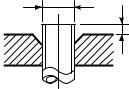
2-4. Recharging of Refrigerant
When it is necessary to recharge refrigerant, charge the specified amount of new refrigerant according to the following steps.
Recover the refrigerant, and check no refrigerant remains in the equipment.
Connect the charge hose to packed valve service port at the outdoor unit’s gas side.
Connect the charge hose of the vacuum pump adapter.
Open fully both packed valves at liquid and gas sides.
Place the handle of the gauge manifold Low in the fully opened position, and turn on the vacuum pump’s power switch. Then, evacuating the refrigerant in the cycle.
When the compound gauge’s pointer has indicated –0,1 Mpa (–76 cmHg), place the handle Low in the fully closed position, and turn off the vacuum pump’s power switch.
Keep the status as it is for 1 to 2 minutes, and ensure that the compound gauge’s pointer does not return.
Set the refrigerant cylinder to the electronic balance, connect the connecting hose to the cylinder and the connecting port of the electronic balance, and charge liquid refrigerant.
(For refrigerant charging, see the figure below.)
• Never charge refrigerant exceeding the specified amount.
‚ If the specified amount of refrigerant cannot be charged, charge refrigerant bit by bit in COOL mode.
ƒDo not carry out additional charging.
When additional charging is carried out if refrigerant leaks, the refrigerant composition changes in the refrigeration cycle, that is characteristics of the air conditioner changes, refrigerant exceeding the specified amount is charged, and working pressure in the refrigeration cycle becomes abnormally high pressure, and may cause a rupture or personal injury.
(INDOOR unit) |
(Liquid side) |
(OUTDOOR unit) |
Opened
(Gas side)
Refrigerant cylinder (With siphon pipe)
Check valve
Closed
Open/Close valve for charging
Service port
Electronic balance for refrigerant charging
Fig. 2-4-1 Configuration of refrigerant charging
– 13 –
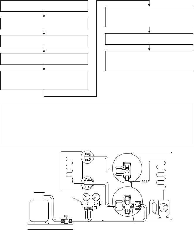
• Be sure to make setting so that liquid can be charged.
‚ When using a cylinder equipped with a siphon, liquid can be charged without turning it upside down.
It is necessary for charging refrigerant under condition of liquid because R410A is mixed type of refrigerant. Accordingly, when charging refrigerant from the refrigerant cylinder to the equipment, charge it turning the cylinder upside down if cylinder is not equipped with siphon.
[ Cylinder with siphon ] |
[ Cylinder without siphon ] |
Gauge manifold |
Gauge manifold |
OUTDOOR unit |
OUTDOOR unit |
Refrigerant
cylinder
Electronic
balance
cylinder Refrigerant
Electronic
balance
Siphon
R410A refrigerant is HFC mixed refrigerant. Therefore, if it is charged with gas, the composition of the charged refrigerant changes and the characteristics of the equipment varies.
Fig. 2-4-2
2-5. Brazing of Pipes
2-5-1. Materials for Brazing
(1)Silver brazing filler
Silver brazing filler is an alloy mainly composed of silver and copper. It is used to join iron, copper or copper alloy, and is relatively expensive though it excels in solderability.
(2)Phosphor bronze brazing filler
Phosphor bronze brazing filler is generally used to join copper or copper alloy.
(3)Low temperature brazing filler
Low temperature brazing filler is generally called solder, and is an alloy of tin and lead. Since it is weak in adhesive strength, do not use it for refrigerant pipes.
•Phosphor bronze brazing filler tends to react with sulfur and produce a fragile compound water solution, which may cause a gas leakage. Therefore, use any other type of brazing filler at a hot spring resort, etc., and coat the surface with a paint.
‚When performing brazing again at time of servicing, use the same type of brazing filler.
2-5-2. Flux
(1)Reason why flux is necessary
•By removing the oxide film and any foreign matter on the metal surface, it assists the flow of brazing filler.
•In the brazing process, it prevents the metal surface from being oxidized.
•By reducing the brazing filler’s surface tension, the brazing filler adheres better to the treated metal.
– 14 –
(2)Characteristics required for flux
•Activated temperature of flux coincides with the brazing temperature.
•Due to a wide effective temperature range, flux is hard to carbonize.
•It is easy to remove slag after brazing.
•The corrosive action to the treated metal and brazing filler is minimum.
•It excels in coating performance and is harmless to the human body.
As the flux works in a complicated manner as described above, it is necessary to select an adequate type of flux according to the type and shape of treated metal, type of brazing filler and brazing method, etc.
(3)Types of flux
•Noncorrosive flux
Generally, it is a compound of borax and boric acid.
It is effective in case where the brazing temperature is higher than 800°C.
•Activated flux
Most of fluxes generally used for silver brazing are this type.
It features an increased oxide film removing capability due to the addition of compounds such as potassium fluoride, potassium chloride and sodium fluoride to the borax-boric acid compound.
(4)Piping materials for brazing and used brazing filler/flux
Piping |
Used brazing |
Used |
material |
filler |
flux |
|
|
|
Copper - Copper |
Phosphor copper |
Do not use |
|
|
|
Copper - Iron |
Silver |
Paste flux |
|
|
|
Iron - Iron |
Silver |
Vapor flux |
|
|
|
• Do not enter flux into the refrigeration cycle.
‚When chlorine contained in the flux remains within the pipe, the lubricating oil deteriorates. Therefore, use a flux which does not contain chlorine.
ƒWhen adding water to the flux, use water which does not contain chlorine (e.g. distilled water or ion-exchange water).
„ Remove the flux after brazing.
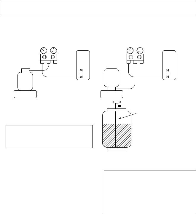
2-5-3. Brazing
As brazing work requires sophisticated techniques, experiences based upon a theoretical knowledge, it must be performed by a person qualified.
In order to prevent the oxide film from occurring in the pipe interior during brazing, it is effective to proceed with brazing while letting dry Nitrogen gas (N2) flow.
Never use gas other than Nitrogen gas.
(1) Brazing method to prevent oxidation
•Attach a reducing valve and a flow-meter to the Nitrogen gas cylinder.
‚Use a copper pipe to direct the piping material, and attach a flow-meter to the cylinder.
ƒApply a seal onto the clearance between the piping material and inserted copper pipe for Nitrogen in order to prevent backflow of the Nitrogen gas.
„When the Nitrogen gas is flowing, be sure to keep the piping end open.
…Adjust the flow rate of Nitrogen gas so that it is lower than 0,05 m3/Hr or 0,02 MPa (0,2kgf/ cm2) by means of the reducing valve.
†After performing the steps above, keep the Nitrogen gas flowing until the pipe cools down to a certain extent (temperature at which pipes are touchable with hands).
‡ Remove the flux completely after brazing.
M Flow meter
Stop valve
Nitrogen gas cylinder
From Nitrogen cylinder
Pipe 


 Nitrogen gas
Rubber plug
Fig. 2-5-1 Prevention of oxidation during brazing
– 15 –
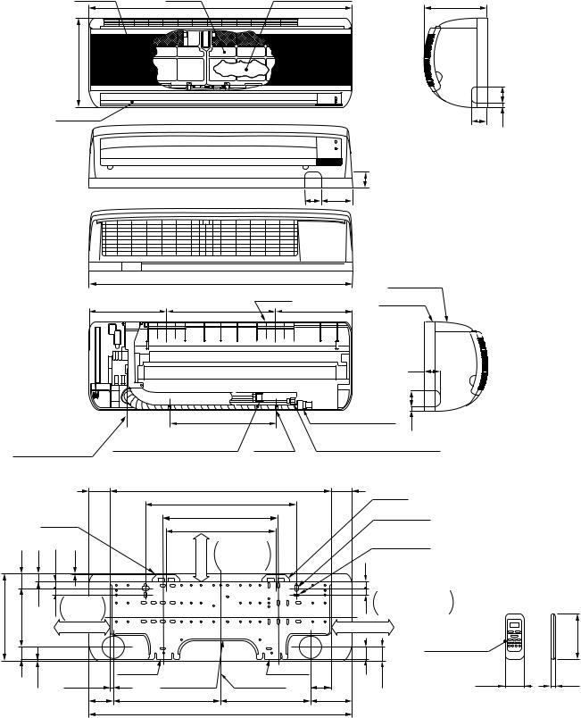
3. CONSTRUCTION VIEWS
3-1. Indoor Unit
RAS-M10YKV-E, RAS-M13YKV-E
RAS-M10YKCV-E, RAS-M13YKCV-E
Air inlet
265
Air outlet
Air filter |
790 |
Heat exchanger |
189 |
|
|
||
|
|
|
,,,,,,@@@@@@€АААААА€€€€€
,,,,,,@@@@@@€АААААА€€€€€
|
50 |
47 |
10 |
|
Knock out system
|
|
|
|
|
|
|
|
|
|
47 |
|
|
|
|
|
|
|
|
|
|
|
|
|
|
50 |
94 |
|
|
|
|
|
|
|
|
|
|
|
|
790 |
|
|
|
Front panel |
|
|
||
|
|
|
|
|
232 |
|
326 |
Hanger |
232 |
|
Back body |
|
|
||
|
|
|
|
|
|
|
|
|
|
||||||
|
|
|
|
|
|
|
|
|
|
|
|
|
|||
|
|
|
|
|
|
|
|
|
|
|
|
47 |
|
|
|
|
|
|
|
|
|
|
|
|
|
|
|
50 |
|
|
|
|
|
|
|
|
|
|
321 |
|
Drain hose (0,54m) |
10 |
Knock out system |
|
|||
|
|
|
|
|
|
|
|
|
|
|
|
|
|||
|
|
|
|
|
|
|
|
|
|
|
|
|
|
||
|
External |
|
Connecting pipe (0,39m) |
Hanger |
Connecting pipe (0,49m) |
|
|
||||||||
|
length reference |
|
|
||||||||||||
|
|
(Flare ø9,52) |
|
(Flare ø6,35) |
|
|
|
|
|
||||||
|
|
|
|
|
|
|
|
|
|
|
|
||||
|
|
|
|
65,5 |
|
|
659 |
|
|
65,5 |
Hanger |
|
|
|
|
|
|
|
|
|
|
|
450 |
|
|
|
|
|
|
||
|
|
|
|
|
|
|
|
|
|
|
|
|
|
|
|
|
|
|
Hanger |
|
|
344 |
|
|
|
For stud bolt |
|
|
|||
|
|
|
|
|
326 |
|
|
|
(ø8~ø10) |
|
|
|
|||
|
46 |
26 |
20 |
2,5 |
|
moreor66 |
|
|
20 |
|
|
|
|||
|
|
Minimum |
|
For stud bolt |
|
|
|||||||||
|
|
|
|
|
|
|
distance |
|
|
(ø6) |
|
|
|
|
|
|
|
|
|
|
|
|
to ceiling |
|
|
|
|
|
|
|
|
|
|
|
|
Minimum |
|
|
|
|
|
20 |
Minimum |
|
|
||
265 |
178,5 |
|
17 |
distance |
|
|
|
|
|
distance to wall |
|
|
|||
|
to wall |
|
|
|
|
|
|
|
|
|
|
||||
|
|
|
|
|
|
|
|
|
|
|
|
|
|
|
|
|
|
|
|
120 or more |
|
|
|
|
|
120 or more |
|
Wireless |
|
136 |
|
|
|
|
|
|
|
|
|
|
|
|
|
|
|
||
|
|
|
|
|
|
|
|
|
|
37 |
|
|
remote control |
|
|
|
|
|
|
|
|
|
|
|
|
|
|
|
|
|
|
|
37 |
3,5 |
|
|
Hanger |
Installation |
|
Hanger |
|
|
40,5 |
|
|
|
|
|
|
|
|
|
|
60,5 |
|
|
|
|
16 |
||||
|
|
10,5 |
|
plate outline |
Center line |
|
|
|
55 |
||||||
|
|
|
|
76 |
|
319 |
|
269 |
126 |
|
|
|
|
|
|
|
|
|
|
|
|
|
790 |
|
|
|
|
|
|
|
|
|
|
|
|
|
|
|
|
– 16 – |
|
|
|
|
|
|
|

3-2. Outdoor Unit
RAS-M18YAV-E |
A leg part |
600 |
|
||
|
ø25 drain hole |
|
RAS-M18YACV-E |
|
115 |
|
|
|
310 bolt long holepitch) |
296 hole pitch) 270 |
76 |
(Anchor |
(ø6 |
|
|
B leg part |
16 |
ø4,5 embossing (ø4STS used) (For sunshade roof attaching)
|
90 |
ø11 × 17U-shape hole |
50 |
|
|
|
(For ø8-ø10 anchor bolt) |
|
|
|
8-ø6 hole
(For fixing outdoor unit)
ø11 × 17 long hole
(For ø8-ø10 anchor bolt)
49,5 |
147 |
21 |
Fan guard |
115,5 |
Hanger
540 |
550 |
8 |
780 |
|
Connecting pipe port
(Pipe dia.ø6,35)
|
Connecting pipe port |
|
|
|
|
|
(Pipe dia.ø9,52) |
|
|
Z |
view |
|
|
|
|
||
|
Mounting dimensions of anchor bolt |
|
|||
|
|
|
600 |
|
|
4 × ø11 × 17U-shape hole |
|
|
|
|
|
(For ø8-ø10 anchor bolt) |
more |
|
|
A |
|
|
or50 |
D |
Intake |
||
|
|
|
|
||
|
|
|
|
|
|
|
Intake |
|
|
|
250 or more |
|
|
|
|
|
|
310 |
C 100 or |
|
|
Outside line |
(Minimum distance |
|
more |
|
|
||
|
|
|
|
of product |
from wall) |
|
200 or more |
|
|
|
|
|
|
|
Outlet |
4 × ø11 × 17 long hole |
|
|
|
|
B |
(For ø8-ø10 anchor bolt) |
|
|
|
|
|
|
|
Valve cover |
157 |
59 |
21
|
Charging |
53 |
Z |
|
|
||
|
53 |
|
|
|
port |
|
|
|
|
|
|
|
|
53 |
|
|
|
|
96,2 |
|
|
122,8 |
|
61 |
|
332 |
|
Earth terminal
Detailed A leg part |
|
||
|
|
|
600 |
|
|
50 |
|
|
|
36 |
R15 |
|
|
11 |
|
|
|
|
Outside line |
|
|
|
of product |
310 |
296 |
R5,5 |
2-ø6 hole |
|
|
||
|
|
|
|
|
|
|
2-ø6 hole |
310 |
296 |
11 |
|
|
|
||
Outside line of product
36 R15
50
600 |
R5,5 |
|
Detailed B leg part
– 17 –
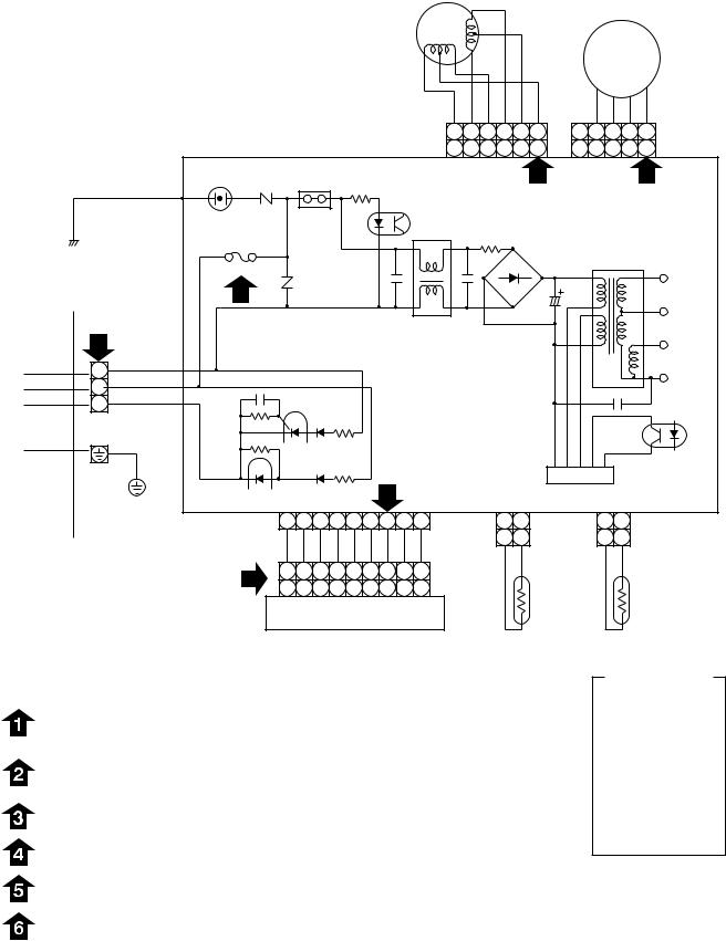
4. WIRING DIAGRAM
FAN MOTOR
4-1. Indoor Unit |
|
|
|
|
|
|
|
LOUVER |
|
|
|
|
|
|
|
|
|
|
|||||
RAS-M10YKV-E, RAS-M13YKV-E |
|
|
|
|
|
|
|
|
|
|
|
|
|
|
|
||||||||
|
|
|
|
|
MOTOR |
|
|
|
|
|
|
DC MOTOR |
|||||||||||
RAS-M10YKCV-E, RAS-M13YKCV-E |
|
|
|
|
|
|
|
|
|
|
|
|
|
|
|
|
|
|
|
||||
|
|
|
|
|
|
|
|
|
|
|
|
|
BLU |
PNK |
YEL |
ORN |
RED |
BRW |
|
|
|
|
|
|
|
|
|
|
|
|
|
|
|
|
|
|
6 |
5 |
4 |
3 |
2 |
1 |
5 |
4 |
3 |
2 |
1 |
|
|
|
|
|
|
|
|
|
|
|
|
|
6 |
5 |
4 |
3 |
2 |
1 |
5 |
4 |
3 |
2 |
1 |
|
|
|
|
R109 |
|
|
|
|
|
|
|
|
CN07 |
|
5 |
|
CN10 |
|
6 |
||||
|
|
|
BLK |
VARISTOR |
|
|
R116 |
|
|
|
|
|
|
|
|
|
|
|
|
||||
|
|
|
|
|
|
|
|
|
|
|
|
|
|
|
|
|
|
|
|
||||
|
|
|
|
|
|
|
|
|
|
IC04 |
|
|
|
|
|
|
|
|
|
|
|||
|
|
|
P04 |
|
|
J04 |
|
|
|
|
|
|
|
|
|
|
|
|
|||||
|
|
|
SG01 DSA |
|
|
|
|
|
|
|
|
|
|
|
|
|
|
|
|
||||
|
|
|
|
|
|
|
|
|
|
|
|
|
|
|
|
|
|
|
|
||||
|
|
|
|
|
|
|
|
|
|
|
|
L01 |
|
|
|
|
|
|
|
|
|
|
|
|
|
|
|
T6,3A 250V |
|
|
|
|
|
|
|
|
R01 |
|
|
|
|
|
|
|
|||
|
|
|
|
|
|
|
|
|
|
|
|
|
|
|
|
|
|
|
|
||||
|
|
|
|
F01 FUSE |
|
|
|
|
|
|
|
|
|
|
|
|
|
DB01 |
|
TO1 |
|
||
|
|
|
|
|
R21 |
|
|
|
|
|
|
|
|
|
|
|
|
|
|
|
DC35V |
||
|
|
|
|
3 |
|
|
|
|
|
|
|
|
|
|
|
|
|
|
|
|
|||
|
|
|
|
|
|
|
|
|
|
|
|
|
|
|
|
|
|
|
|
|
|||
|
INDOOR |
|
|
|
|
|
|
|
|
|
|
|
|
|
|
|
|
|
|
|
|
||
|
|
|
|
|
|
|
|
|
|
|
|
|
|
|
|
|
|
|
|
|
DC12V |
||
|
TERMINAL |
|
|
|
|
|
|
|
|
C15 |
C01 |
|
|
C02 |
|
|
|
|
|||||
|
BLOCK |
|
|
|
|
|
|
|
|
|
|
|
|
|
|
|
|
||||||
|
|
|
|
|
|
|
|
|
|
|
|
|
|
|
|
|
|
|
|
|
|
||
|
2 |
|
|
|
|
|
|
|
|
|
|
|
|
|
|
|
|
|
|
|
|
|
DC7V |
|
1 BLK |
CN30 |
|
|
|
|
|
|
|
|
|
|
|
|
|
|
|
|
|
|
|
DC0V |
|
|
2 |
WHI |
|
|
|
|
|
|
|
|
MAIN P.C. BOARD |
|
|
|
|
||||||||
|
|
|
|
|
|
|
|
|
C06 |
|
|
||||||||||||
|
3 |
RED |
|
|
|
|
|
|
|
|
|
|
(MCC-772) |
|
|
|
IC02 |
||||||
|
|
|
|
|
|
|
|
|
|
|
|
|
|
|
|
|
|
|
|
|
|
|
|
|
|
GRN & YEL |
|
|
|
|
|
|
|
|
|
|
|
|
|
|
|
|
|
|
|
|
|
|
|
|
|
CN23 |
|
|
|
|
|
|
|
|
|
|
|
|
|
|
IC |
|
|
|
|
|
|
|
|
|
|
CN13 |
|
4 |
|
|
|
CN03 |
IC01 |
|
|
|
|||||||
OUTDOOR INDOOR |
|
|
|
|
|
|
|
|
|
CN01 |
|
||||||||||||
|
|
1 |
2 |
3 |
4 |
5 |
6 |
7 |
8 |
9 |
|
|
1 |
2 |
|
|
1 |
2 |
|
|
|||
UNIT |
UNIT |
|
|
|
|
|
|
|
|
||||||||||||||
|
|
BLU |
BLU |
BLU |
BLU |
BLU |
BLU |
PNK |
BLK |
WHI |
|
|
1 |
2 |
|
|
1 |
2 |
|
|
|||
|
|
|
|
|
|
|
|
|
|
|
|||||||||||||
|
|
|
|
|
|
|
BLK |
BLK |
|
|
BLK |
BLK |
|
|
|||||||||
|
|
|
|
1 |
1 |
2 |
3 |
4 |
5 |
6 |
7 |
8 |
9 |
|
|
|
|
|
|
|
|
|
HEAT |
|
|
|
|
1 2 3 4 5 6 7 8 9 CN25 |
|
|
|
|
|
|
|
|
|||||||||||
|
|
|
|
|
|
|
|
THERMO |
|
|
EXCHANGER |
||||||||||||
|
|
|
|
|
INFRARED RAYS RECEIVE |
|
|
|
|
SENSOR |
|
|
|
SENSOR |
|||||||||
|
|
|
|
|
AND INDICATION PARTS |
|
|
|
|
(TA) |
|
|
|
(TC) |
|||||||||
Table 4-1-1 Simple check points for diagnosing faults
Check items |
|
Diagnosis result |
|
|
|
OPERATION |
|
Check to see if the OPERATION indicator goes on and off when the main |
|
switch or breaker is turned on, or the power cord is plugged in the wall |
|
indicator |
|
outlet. (Check the primary and secondary voltage of transformer.) |
|
|
|
|
|
|
Terminal |
|
Check for power supply voltage between • – ‚. (Refer to the name |
|
plate.) (Check the primary and secondary voltage of transformer.) |
|
block |
|
|
|
Check for fluctuate voltage between ‚ – ƒ. (DC 15 to 60V) |
|
|
|
|
|
|
|
Fuse |
|
Check to determine if the fuse is open. |
6,3A |
|
(Check Varistor : R109, R21) |
|
|
|
DC 5V |
|
Check for voltage at the pink lead of the infrared rays receive parts. |
|
(Check the transformer and the rated voltage power supply circuit.) |
|
|
|
|
|
|
|
DC 12V |
|
Check for voltage at the •ƒ lead of louver motor. |
|
(Check the transformer and the rated voltage power supply circuit.) |
|
|
|
|
|
|
|
DC 35V |
|
Check for voltage at the CN10 connector side point. |
|
(Check the transformer and the rated voltage power supply circuit.) |
|
|
|
|
|
|
|
For detailed diagnostic procedure, refer to the service data. |
||
DSA : Surge Absorber |
|
|
COLOR
IDENTIFICATION
BRW : BROWN RED : RED WHI : WHITE YEL : YELLOW BLU : BLUE BLK : BLACK GRY : GRAY PNK : PINK ORN : ORANGE
GRN : GREEN & &YEL YELLOW
– 18 –
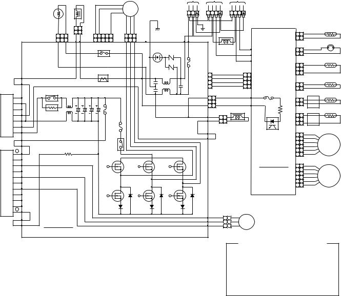
4-2. Outdoor Unit
RAS-M18YAV-E
FAN MOTOR
REACTOR
|
|
4 way |
|
|
|
|
FM |
|
|
|
valve |
|
|
|
|
|
|
|
|
|
1 |
2 |
GRY PNK |
YEL |
RED WHI BLK |
|
|
|
3 2 1 |
1 |
2 |
5 4 3 2 1 |
1 2 3 |
|
|
|
|
|
|
|
||||
|
|
3 2 1 |
|
|
5 4 3 2 1 |
1 2 3 |
|
|
|
|
CN701 |
P08 |
P07 |
CN301 |
CN300 |
P06 |
|
|
|
|
|
|
RELAY |
|
|
|
|
|
|
|
|
RY04 |
|
|
|
|
|
P09 |
|
|
CT |
|
|
|
|
|
|
|
|
|
|
|
|
ORN |
|
P10 |
|
|
|
|
|
|
|
|
POWER RELAY |
|
C13 |
C15 |
|
|
|
|
|
|
|
|
|
|
||
CONVERTER MODULE |
G |
|
|
|
|
F04 |
|
|
|
E |
|
|
|
|
F03 |
|
|
|
|
|
|
|
FUSE |
|
||
|
A |
|
|
|
|
|
||
|
ELECTRONIC |
|
|
|
15A |
|
||
|
~ |
STARTER |
|
|
|
|
|
|
|
– |
L01 C12 C14 |
FUSE |
|
||||
|
~ |
|
|
|
|
|
||
DB01 |
|
|
|
|
3,15A |
|
||
|
|
|
|
|
|
|
|
|
+P19
YEL |
P20 |
RELAY |
|
|
+ |
RY06 |
|
|
|
||
|
BU |
|
|
|
EU |
|
|
MODULE |
BV |
|
|
EV |
|
||
|
|
||
|
BW |
|
|
IGBT |
EW |
|
|
BX |
|
||
|
|
||
|
BY |
|
|
|
BZ |
|
|
Q200 |
– |
|
|
|
|
||
BLU |
P18 |
P.C. BOARD |
|
MCC-758 |
|||
|
P17 |
||
|
|
|
POWER |
To |
To |
|
|
SUPPLY |
INDOOR |
INDOOR |
|
|
220–230–240V~ UNIT |
UNIT |
|
|
|
50/60Hz |
A |
B |
|
|
~ ~ ~ |
~ ~ ~ ~ |
~ ~ ~ ~ |
|
|
L N |
1 2 3 |
1 2 3 |
|
|
|
|
THERMOSTAT for COMPRESSOR |
|
|
|
|
CN01 1 |
TE |
|
|
|
1 |
|
BLK |
WHI BLK |
|
WHI 2 2 |
|
|
|
|
||
SURGE |
|
REACTOR |
ORN |
|
|
|
|
|
|
||||
ABSORBER |
|
P04 |
CN08 1 |
1 |
|
|
|||||||
F01 |
|
|
|
|
RED |
P05 |
WHI 2 |
2 |
|
|
|||
|
|
|
|
WHI |
|
|
|
|
|
||||
|
|
|
|
P06 |
|
|
|
|
TD |
||||
FUSE |
|
|
|
|
|
|
|
|
|
1 |
1 |
|
|
25A |
|
|
|
|
|
|
|
|
CN02 |
|
|
||
|
|
BRW |
|
BRW |
|
|
|
WHI |
2 |
2 |
|
|
|
VARISTOR |
1 |
|
1 1 |
|
3 |
3 |
|
|
|||||
CN704 |
2 |
RED |
|
RED |
2 2 |
CN15 |
|
|
|
|
TO |
||
ORN |
|
ORN |
|
|
|
|
|||||||
|
3 |
YEL |
|
YEL |
3 3 |
|
CN03 1 |
1 |
|
|
|||
|
4 |
|
|
|
|
4 |
4 |
F01 |
WHI 2 |
2 |
|
|
|
|
|
|
|
|
|
|
|
|
|
||||
L03 |
|
|
|
|
|
|
|
FUSE 6,3A |
|
|
|
|
TS |
1 |
1 |
|
|
BLK |
P02 |
CN04 1 |
1 |
|
|||||
CN501 |
|
|
BLK |
|
|||||||||
|
|
|
|
|
|||||||||
3 |
3 |
|
|
|
|
|
|
BLK 2 |
2 |
|
|||
|
|
|
GRY |
P01 |
|
|
|||||||
|
|
|
|
|
|
|
|
||||||
|
|
|
|
|
|
|
|
|
TGa |
||||
P11 |
YEL |
|
|
|
|
|
|
|
|
|
|
||
|
|
|
|
|
|
CN05 |
1 |
1 |
|
|
|||
|
|
1 1 |
|
|
|
|
|
2 |
2 |
YEL |
|
||
P12 |
|
2 2 |
REACTOR |
|
|
YEL |
3 |
3 |
|
|
|||
YEL |
|
|
|
|
|
|
|||||||
P13 |
|
PUR |
|
|
|
|
PHOTO |
|
6 |
6 |
GRY |
|
|
|
|
|
|
|
|
|
|
||||||
|
|
|
|
|
|
|
|
COUPLER |
|
5 |
5 |
RED |
|
|
P14 |
|
|
|
|
|
|
CN14 |
4 |
4 |
BLU |
P.M.V. |
|
|
|
|
|
|
|
|
|
|
3 |
3 |
ORN |
A UNIT |
|
|
|
|
|
|
|
|
|
SUB |
|
2 |
2 |
YEL |
|
|
|
|
|
|
|
|
|
|
WHI |
|
|||
|
|
|
|
|
|
|
|
|
1 |
1 |
|
||
|
|
|
|
|
|
|
|
P.C. BOARD |
|
|
|
|
|
|
|
|
|
|
|
|
|
MCC-775 |
6 |
6 |
GRY |
|
|
|
|
|
|
|
|
|
|
|
|
5 |
5 |
RED |
|
|
|
|
|
|
|
|
|
|
CN13 |
4 |
4 |
BLU |
P.M.V. |
|
|
|
|
|
|
|
|
|
3 |
3 |
ORN |
B UNIT |
|
|
|
|
|
|
|
|
|
|
|
2 |
2 |
YEL |
|
|
|
|
|
|
|
|
|
|
|
WHI |
|
||
|
|
|
|
|
|
|
|
|
|
1 |
1 |
|
|
P21 |
RED |
1 |
1 |
|
|
|
|
|
|
|
|
|
|
P22 |
WHI |
|
CM |
COMPRESSOR |
|
|
|
|
|||||
2 2 |
|
|
|
|
|
||||||||
P23 |
BLK |
|
|
|
|
|
|||||||
3 |
3 |
|
|
|
|
|
|
|
|
|
|||
|
|
|
|
|
|
|
|
|
|
|
|
||
COLOR IDENTIFICATION
BLK |
: BLACK |
WHI |
: WHITE |
BLU |
: BLUE |
BRW |
: BROWN |
ORN |
: ORANGE |
RED |
: RED |
GRY |
: GRAY |
YEL |
: YELLOW |
PNK |
: PINK |
PUR : PURPLE |
|
SKB |
: SKY-BLUE |
|
|
P.M.V. : PULSE MODULATING VALVE
– 19 –
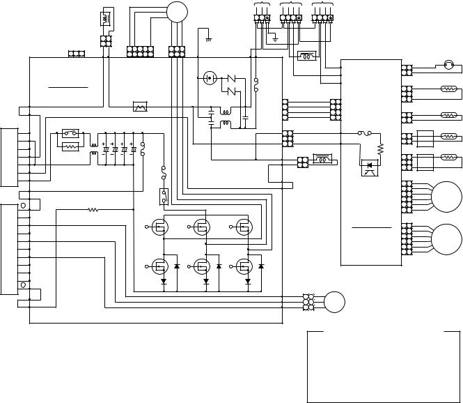
RAS-M18YACV-E
|
POWER |
To |
To |
|
SUPPLY |
INDOOR |
INDOOR |
|
220–230–240V~ UNIT |
UNIT |
|
FAN MOTOR |
50/60Hz |
A |
B |
|
|
|
|
|
|
|
FM |
|
|
~ ~ ~ |
~ ~ ~ ~ |
~ ~ ~ ~ |
|
REACTOR |
|
|
|
|
|
|
|
|
L N |
1 2 3 |
1 2 3 |
||
|
|
|
|
|
|
|
|
|
|
||||
1 |
2 |
GRY PNK |
|
YEL |
RED WHI BLK |
|
|
|
|
||||
1 |
2 |
5 |
4 |
3 |
2 |
1 |
1 |
2 |
3 |
|
|
|
|
3 2 1 |
|
BLK |
WHI BLK |
|
THERMOSTAT for COMPRESSOR |
||||||||
|
5 |
4 |
3 |
2 |
1 |
1 |
2 |
3 |
|
|
|||
|
|
CN701 |
P08 |
P07 |
|
CN301 |
CN300 |
P06 |
SURGE |
|
REACTOR |
ORN |
|
|
|
|
|
|
|||||
|
|
|
|
|
|
|
|
|
|
ABSORBER |
|
P04 |
CN08 1 |
1 |
|
|
|||||||
|
|
P.C. BOARD |
|
|
|
|
|
|
|
F01 |
|
|
|
|
RED |
P05 |
WHI 2 |
2 |
|
|
|||
|
|
|
|
|
|
|
|
|
|
|
|
|
WHI |
|
|
|
|
|
|||||
|
|
MCC-758 |
|
|
|
|
|
|
|
|
|
|
|
P06 |
|
|
|
|
TD |
||||
|
|
|
|
|
|
|
|
|
FUSE |
|
|
|
|
|
|
|
|
1 |
1 |
|
|||
|
|
|
|
|
|
|
|
|
|
25A |
|
|
|
|
|
|
|
|
CN02 |
|
|
||
|
|
|
|
|
|
|
CT |
|
|
|
|
BRW |
|
BRW |
|
|
|
WHI |
2 |
2 |
|
|
|
|
|
P09 |
|
|
|
|
|
|
VARISTOR |
1 |
|
1 1 |
|
3 |
3 |
|
|
||||||
|
|
|
|
|
|
|
|
|
|
CN704 |
2 |
RED |
|
RED |
2 2 |
CN15 |
|
|
|
|
TO |
||
ORN |
|
P10 |
|
|
|
|
|
|
|
ORN |
|
ORN |
CN03 1 |
|
|
||||||||
|
|
|
|
|
|
|
|
|
|
|
3 |
YEL |
|
YEL |
3 3 |
|
1 |
|
|
||||
|
|
|
|
|
|
|
|
|
|
|
4 |
|
|
|
|
4 |
4 |
F01 |
WHI 2 |
2 |
|
|
|
|
|
POWER RELAY |
|
|
|
|
|
|
|
|
|
|
|
|
|
|
|
|
|
||||
|
|
|
C13 |
C15 |
|
|
L03 |
|
|
|
|
|
|
|
FUSE 6,3A |
|
|
|
|
TS |
|||
|
|
|
|
|
|
|
|
|
|
|
|
|
|
|
|
|
|||||||
|
|
|
|
|
|
1 |
1 |
|
|
BLK |
P02 |
CN04 1 |
1 |
|
|||||||||
|
G |
|
|
|
|
|
|
|
|
CN501 |
|
|
BLK |
|
|||||||||
|
|
|
|
|
|
|
|
|
|
|
|
|
|
||||||||||
CONVERTER MODULE |
|
|
|
|
|
|
|
|
|
|
|
|
|
|
|
|
BLK 2 |
2 |
|
||||
– |
|
L01 |
C12 |
C14 |
FUSE |
|
P12 |
YEL |
|
|
|
|
|
|
|
|
|||||||
|
E |
|
|
|
|
|
F03 |
|
|
3 |
3 |
|
|
GRY |
P01 |
|
|
|
|
|
|||
|
|
|
|
|
|
FUSE |
|
|
|
|
|
|
|
|
|
|
TGa |
||||||
|
A |
ELECTRONIC |
|
|
|
|
15A |
|
P11 |
YEL |
|
|
|
|
|
|
|
|
|
|
|||
|
|
|
|
|
|
|
|
|
|
|
|
CN05 |
1 |
1 |
|
|
|||||||
|
~ |
STARTER |
|
|
|
|
|
|
|
|
|
1 1 |
|
|
|
|
|
2 |
2 |
YEL |
|
||
|
|
|
|
|
|
|
|
F04 |
|
|
|
2 2 |
REACTOR |
|
|
YEL |
3 |
3 |
|
|
|||
DB01 |
~ |
|
|
|
|
|
3,15A |
|
P13 |
|
|
|
|
|
|
|
PHOTO |
|
6 |
6 |
GRY |
|
|
+ |
P19 |
|
|
|
|
|
|
|
|
|
PUR |
|
|
|
|
COUPLER |
|
|
|||||
|
|
|
|
|
|
|
|
|
|
|
|
|
|
|
|
|
5 |
5 |
RED |
|
|||
YEL |
|
P20 |
|
|
|
|
RELAY |
|
|
P14 |
|
|
|
|
|
|
|
4 |
4 |
BLU |
P.M.V. |
||
|
|
|
|
|
|
|
|
|
|
|
|
|
|
|
CN14 3 |
3 |
ORN |
A UNIT |
|||||
|
|
|
|
|
|
|
|
|
|
|
|
|
|
|
|
|
|||||||
|
+ |
|
|
|
|
|
RY06 |
|
|
|
|
|
|
|
|
|
SUB |
|
2 |
2 |
YEL |
|
|
|
|
|
|
|
|
|
|
|
|
|
|
|
|
|
|
|
|
WHI |
|
||||
|
BU |
|
|
|
|
|
|
|
|
|
|
|
|
|
|
|
|
|
1 |
1 |
|
||
|
|
|
|
|
|
|
|
|
|
|
|
|
|
|
|
|
P.C. BOARD |
|
|
|
|
||
|
EU |
|
|
|
|
|
|
|
|
|
|
|
|
|
|
|
|
MCC-775 |
6 |
6 |
GRY |
|
|
MODULE |
BV |
|
|
|
|
|
|
|
|
|
|
|
|
|
|
|
|
|
|
5 |
5 |
RED |
P.M.V. |
|
|
|
|
|
|
|
|
|
|
|
|
|
|
|
|
|
|
|
1 |
1 |
WHI |
||
|
EV |
|
|
|
|
|
|
|
|
|
|
|
|
|
|
|
|
|
|
4 |
4 |
BLU |
|
|
|
|
|
|
|
|
|
|
|
|
|
|
|
|
|
|
|
|
CN13 3 |
3 |
ORN |
B UNIT |
|
|
BW |
|
|
|
|
|
|
|
|
|
|
|
|
|
|
|
|
|
|
2 |
2 |
YEL |
|
IGBT |
EW |
|
|
|
|
|
|
|
|
|
|
|
|
|
|
|
|
|
|
|
|
|
|
BX |
|
|
|
|
|
|
|
|
|
|
|
|
|
|
|
|
|
|
|
|
|
|
|
|
|
|
|
|
|
|
|
|
|
|
|
|
|
|
|
|
|
|
|
|
|
|
|
|
BY |
|
|
|
|
|
|
|
|
|
|
|
|
|
|
|
|
|
|
|
|
|
|
|
BZ |
|
|
|
|
|
|
|
|
|
|
|
|
|
|
|
|
|
|
|
|
|
|
Q200 |
– |
|
|
|
|
|
|
|
|
|
|
|
|
|
|
|
|
|
|
|
|
|
|
|
|
|
|
|
|
|
|
|
P21 |
RED |
|
|
|
|
|
|
|
|
|
|
|
||
|
|
|
|
|
|
|
|
|
|
1 |
1 |
|
|
|
|
|
|
|
|
|
|||
|
|
|
|
|
|
|
|
|
|
P22 |
WHI |
|
CM |
COMPRESSOR |
|
|
|
|
|||||
BLU |
|
P18 |
|
|
|
|
|
|
|
2 2 |
|
|
|
|
|
||||||||
|
|
|
|
|
|
|
|
P23 |
BLK |
|
|
|
|
|
|||||||||
|
|
|
|
|
|
|
|
3 |
3 |
|
|
|
|
|
|
|
|||||||
|
|
P17 |
|
|
|
|
|
|
|
|
|
|
|
|
|
|
|
|
|
|
|
||
|
|
|
|
|
|
|
|
|
|
|
|
|
|
|
|
|
|
|
|
|
|
|
|
COLOR IDENTIFICATION
BLK : BLACK
BLU : BLUE ORN : ORANGE GRY : GRAY PNK : PINK SKB : SKY-BLUE
WHI : WHITE BRW : BROWN RED : RED YEL : YELLOW PUR : PURPLE
P.M.V. : PULSE MODULATING VALVE
– 20 –
5. SPECIFICATIONS OF ELECTRICAL PARTS
5-1. Indoor Unit
RAS-M10YKV-E, RAS-M13YKV-E / RAS-M10YKCV-E, RAS-M13YKCV-E
No. |
Parts name |
Type |
Specifications |
|
1 |
Fan motor (for indoor) |
TICF-35-19-4 |
DC35V, 19W |
|
2 |
Thermo. sensor (TA-sensor) |
( – ) |
10kΩ at 25°C |
|
3 |
DC-DC transformer (T01) |
SWT-34 or SWT-46 |
DC390V, Secondary DC35V, 12V, 7V |
|
4 |
Microcomputer |
TMP87PM40AF or |
|
|
TMP87CM40AF |
|
|||
|
|
|
||
5 |
Heat exchanger temp. sensor |
( – ) |
10kΩ at 25°C |
|
(TC-sensor) |
||||
|
|
|
||
6 |
Line filter (L01) |
UF-253Y0R7 |
25mH, AC0,7A |
|
7 |
Diode (DB01) |
RBV-406 or D3SBA60 |
4A, 600V |
|
8 |
Capacitor (C02) |
KMH450VNSN100M25B |
100μF, 450V |
|
9 |
Fuse (F01) |
TSCR6,3A |
T6,3A, 250V |
|
10 |
Power supply IC (IC01) |
MA2830-FJ |
4A, 600V |
|
11 |
Varistor (R21, R109) |
15G561K |
560V |
|
12 |
Resistor (R01) |
ERF-5TK5R6 |
5,6Ω, 5W |
|
13 |
Louver motor |
MP35EA7 |
Output (Rated) 2W, 10poles, 1phase DC12V |
|
|
|
|
|
5-2. Outdoor Unit
RAS-M18YAV-E / RAS-M18YACV-E
No. |
Parts name |
|
Model name |
|
Rating |
|
1 |
SC coil (Noise filter) |
|
L03 |
SC-15-S06J |
|
15A, 0,6mH |
|
L01 |
SC-20-01J |
|
20A, 150µH |
||
|
|
|
|
|||
2 |
DC-DC transformer |
|
SWT-43 |
|
Primary side DC280V |
|
|
|
Secondary side |
||||
|
|
|
|
|
|
7,5V x 1, 13V x 1, 26,5V x 3, 16V x 1, 15V x 1 |
3 |
Reactor |
|
CH38Z-K |
|
L=10mH, 16A x 2 |
|
4 |
Reactor |
|
CH43Z-K |
|
L=10mH, 1A |
|
5 |
Outside fan motor |
|
ICF-140-40-7 |
|
DC140V, 40W |
|
6 |
Fan control relay |
|
AJQ1341 |
|
Coil DC12V |
|
|
|
Contact AC125V, 3A |
||||
|
|
|
|
|
|
|
7 |
Suction temp. sensor |
|
(Inverter attached) |
|
10kΩ (25°C) |
|
(TS sensor) |
|
|
||||
|
|
|
|
|
||
8 |
Discharge temp. sensor |
|
(Inverter attached) |
|
62kΩ (20°C) |
|
(TD sensor) |
|
|
||||
|
|
|
|
|
||
9 |
Outside air temp. sensor |
|
(Inverter attached) |
|
10kΩ (25°C) |
|
(TO sensor) |
|
|
||||
|
|
|
|
|
||
10 |
Temp. sensor at A room |
|
(Inverter attached) |
|
RAS-M18YACV-E .......... 10kΩ (25°C) |
|
gas side (TGa sensor) |
|
|
RAS-M18YAV-E ............. 62kΩ (20°C) |
|||
|
|
|
|
|||
11 |
Terminal block (9P) |
|
——— |
20A, AC250V |
||
12 |
Terminal block (3P) |
|
——— |
20A, AC250V |
||
|
|
|
|
For protection of |
|
3,15A, AC250V |
|
|
|
|
switching power source |
|
|
|
|
|
|
|
|
|
13 |
Fuse |
|
For protection of transistor |
|
15A, AC250V |
|
|
module breakage |
|
||||
|
|
|
|
|
|
|
|
|
|
|
For protection of |
|
25A, AC250V |
|
|
|
|
inverter input overcurrent |
|
|
|
|
|
|
|
|
|
14 |
Electrolytic capacitor |
|
LLQ2G501KHUATF |
|
500µF, DC400V X 4 pieces |
|
|
400LISN500K35F |
|
||||
|
|
|
|
|
|
|
15 |
Transistor module |
|
6MBI25GS-060-01 |
|
25A, 600V |
|
16 |
Compressor |
|
DA130A1F-21F |
|
3-phases 4-poles 1100W |
|
17 |
Compressor thermo. |
|
PW-2AL |
|
OFF: 125 ± 4°C, ON: 90 ± 5°C |
|
18 |
Converter module |
|
MP7002 |
|
Diode: 25A, 600V, IGBT: 40A, 600V |
|
19 |
Heat exchanger temp. sensor |
(Inverter attached) |
|
10kΩ at 25°C |
||
(TE-sensor) (H/P only) |
|
|
||||
|
|
|
|
|
||
– 21 –
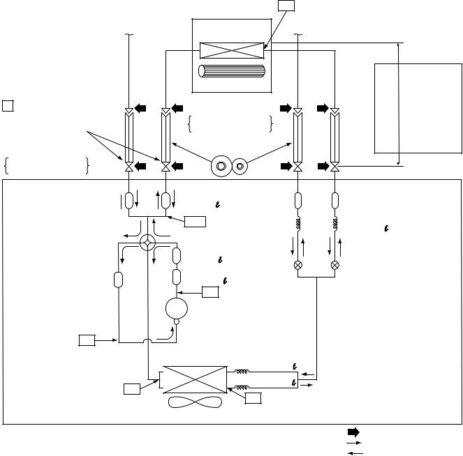
6. REFRIGERANT CYCLE DIAGRAM
6-1. Refrigerant Cycle Diagram
RAS-M10YKV-E, RAS-M13YKV-E RAS-M18YAV-E
To B room
P Pressure measurement
Gauge attaching port
Vacuum pump connecting port
Deoxidized copper pipe
Both A and B rooms
Outer dia. : 9,52mm
Thickness : 0,8mm
Muffler  Ø25 x 80
4 way valve (VHV-0213)
Accumulating tank Ø51 x 200  (290cc)
TS
Temp. measurement T2
INDOOR UNIT |
T1 |
Temp. measurement |
|
|
|
|
|
|
|
|
|
Indoor heat |
To B room |
|
|
|
|
exchanger |
|
heightAllowable |
10m:difference |
lengthpipeAllowable |
|
Cross flow fan |
|
Per 1 unit |
|||
|
|
|
|
||
|
|
|
|
|
|
Deoxidized copper pipe |
|
|
|
|
Max. : 20m |
|
|
|
|
Total : 30m |
|
Both A and B rooms |
|
|
|
|
|
|
|
|
|
|
|
Outer dia. : 6,35mm |
|
|
|
|
|
Thickness : 0,8mm |
|
|
|
|
|
Sectional shape |
|
|
|
|
|
of heat insulator |
|
|
|
|
|
Muffler |
|
Strainer |
|
Strainer |
Ø25 x 80 |
|
|
||
|
|
|
|
|
TGa |
|
|
|
Capillary |
|
|
|
|
Ø2,2 x 200 |
Muffler |
|
|
|
|
Ø25 x 80 |
|
|
|
Pulse modulating |
Muffler |
|
|
|
valve at liquid side |
|
|
|
(SEV15RC2) |
|
Ø25 x 160 |
|
|
|
|
|
|
|
|
|
TD |
|
|
|
|
Compressor |
|
|
|
|
DA130A1F-21F |
|
|
||
Outdoor heat |
Split capillary |
|
|
|
exchanger |
|
|
||
|
Ø1,5 x 200 |
|
|
|
|
|
|
|
|
|
|
Ø1,5 x 200 |
|
|
|
|
TE |
|
|
Propeller fan |
|
|
|
Refrigerant amount : 1,15kg |
OUTDOOR UNIT |
|
NOTE : |
Gas leak check position |
|
|
|
|
|
Refrigerant flow (Cooling) |
|
|
|
|
Refrigerant flow (Heating) |
Table 6-1-1
Total length in two rooms |
Each length in one room |
Unnecessary to add refrigerant |
||
|
|
|||
A room |
B room |
|||
|
|
|||
|
|
|
|
|
(Standard) 10 m |
5 m |
5 m |
Do not add the refrigerant |
|
|
|
|
|
|
(Maximum) 30 m |
20 (10) m |
10 (20) m |
Do not add the refrigerant |
|
|
|
|
|
|
NOTE :
•The maximum pipe length of this air conditioner is 30 m. The additional charging of refrigerant is unnecessary because this air conditioner is designed with charge-less specification.
•To connect only one indoor unit, use connecting pipe with length by 5m or more.
–22 –
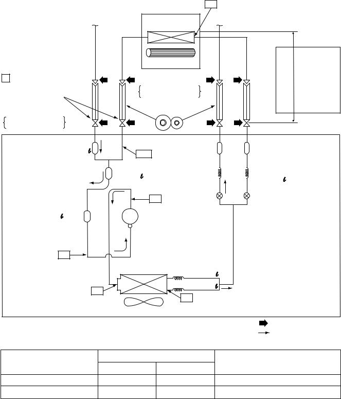
RAS-M10YKCV-E, RAS-M13YKCV-E |
|
|
|
|
|
|
RAS-M18YACV-E |
|
|
|
|
|
|
|
INDOOR UNIT |
T1 |
Temp. measurement |
|
|
|
|
|
|
|
|
|
|
To B room |
Indoor heat |
To B room |
|
|
|
|
|
exchanger |
|
heightAllowable |
10m:difference |
lengthpipeAllowable |
|
|
Cross flow fan |
|
Per 1 unit |
|||
|
|
|
|
|
||
|
|
|
|
|
|
|
P Pressure measurement |
Deoxidized copper pipe |
|
|
|
|
Max. : 20m |
|
|
|
|
Total : 30m |
||
Both A and B rooms |
|
|
|
|
||
Gauge attaching port |
|
|
|
|
|
|
Outer dia. : 6,35mm |
|
|
|
|
|
|
Vacuum pump connecting port |
Thickness : 0,8mm |
|
|
|
|
|
Deoxidized copper pipe |
Sectional shape |
|
|
|
|
|
of heat insulator |
|
|
|
|
|
|
Both A and B rooms |
|
|
|
|
|
|
|
|
|
|
|
|
|
Outer dia. : 9,52mm |
|
|
|
|
|
|
Thickness : 0,8mm |
|
|
|
|
|
|
Muffler |
|
Strainer |
Ø25 x 80 |
|
|
|
TGa |
|
|
|
|
|
Muffler |
Capillary |
|
Ø25 x 80 |
|
|
Ø2,2 x 200 |
|
|
|
|
|
|
|
|
Pulse modulating |
|
TD |
|
|
|
valve at liquid side |
Accumulating tank |
|
|
|
|
(SEV15RC2) |
Compressor |
|
|
|||
Ø51 x 200 |
|
|
|||
(290cc) |
DA130A1F-21F |
|
|
||
TS |
|
|
|
|
|
|
Outdoor heat |
Split capillary |
|
|
|
|
exchanger |
|
|
||
|
|
Ø1,5 x 200 |
|
|
|
|
|
|
|
|
|
Temp. measurement |
T2 |
|
Ø1,5 x 200 |
|
|
|
|
|
|
||
|
|
|
TE |
|
|
|
Propeller fan |
|
|
|
Refrigerant amount : 1,15kg |
|
|
|
|
|
|
|
OUTDOOR UNIT |
|
NOTE : |
Gas leak check position |
|
|
|
|
|
|
Refrigerant flow |
|
Table 6-1-2 |
|
|
||
Total length in two rooms |
Each length in one room |
Unnecessary to add refrigerant |
|||
A room |
|
B room |
|||
|
|
|
|
||
(Standard) 10 m |
5 m |
|
5 m |
Do not add the refrigerant |
|
(Maximum) 30 m |
20 (10) m |
|
10 (20) m |
Do not add the refrigerant |
|
NOTE :
•The maximum pipe length of this air conditioner is 30 m. The additional charging of refrigerant is unnecessary because this air conditioner is designed with charge-less specification.
–23 –
6-2. Operation Data
<Cooling>
Temperature |
No. of |
Operating combination |
Standard |
Heat exchanger |
Indoor |
Outdoor |
Compressor |
|||
condition (°C) |
operating |
(Unit) |
pressure |
pipe temp. |
fan |
fan |
revolution |
|||
|
|
|
|
|
|
|||||
Indoor |
Outdoor |
units |
A |
B |
P (MPa) |
T1 (°C) |
T2 (°C) |
mode |
mode |
(rps) |
|
|
|
|
|
||||||
|
|
|
|
|
|
|
|
|
|
|
|
|
|
M13YKCV-E |
|
0,7 to 0,9 |
9 to 11 |
46 to 48 |
High |
High |
62 |
|
|
|
M13YKV-E |
|
||||||
|
|
1 unit |
|
|
|
|
|
|
|
|
|
|
|
|
|
|
|
|
|
|
|
|
|
|
M10YKCV-E |
0,9 to 1,1 |
11 to 13 |
45 to 47 |
High |
MED. |
38 |
|
|
|
|
|
|||||||
27/19 |
35/– |
|
|
M10YKV-E |
|
|
|
|
|
|
|
|
|
|
|
|
|
|
|
||
|
M13YKCV-E |
M10YKCV-E |
0,8 to 1,0 |
11 to 13 |
50 to 52 |
High |
High |
74 |
||
|
|
|
||||||||
|
|
2 units |
M13YKV-E |
M10YKV-E |
|
|
|
|
|
|
|
|
|
|
|
|
|
|
|
|
|
|
|
M10YKCV-E |
M10YKCV-E |
0,8 to 1,0 |
10 to 12 |
50 to 52 |
High |
High |
74 |
|
|
|
|
||||||||
|
|
|
M10YKV-E |
M10YKV-E |
|
|
|
|
|
|
|
|
|
|
|
|
|
|
|
|
|
<Heating>
Temperature |
No. of |
Operating combination |
Standard |
Heat exchanger |
Indoor |
Outdoor |
Compressor |
||||
condition (°C) |
operating |
(Unit) |
pressure |
pipe temp. |
fan |
fan |
revolution |
||||
|
|
|
|
|
|
||||||
Indoor |
Outdoor |
units |
A |
B |
P (MPa) |
T1 (°C) |
T2 (°C) |
mode |
mode |
(rps) |
|
|
|
|
|
|
|||||||
|
|
|
|
|
|
|
|
|
|
|
|
|
|
1 unit |
M13YKV-E |
|
3,5 to 3,7 |
53 to 55 |
0 to 2 |
High |
High |
79 |
|
|
|
|
|
|
|
|
|
|
|
||
20/– |
7/6 |
|
M10YKV-E |
3,3 to 3,5 |
48 to 50 |
0 to 2 |
High |
MED. |
63 |
||
|
|
||||||||||
|
|
|
|
|
|
|
|
|
|||
2 units |
M13YKV-E |
M10YKV-E |
2,5 to 2,7 |
41 to 43 |
–2 to 0 |
High |
High |
97 |
|||
|
|
||||||||||
|
|
|
|
|
|
|
|
|
|
||
|
|
M10YKV-E |
M10YKV-E |
2,5 to 2,7 |
41 to 43 |
–2 to 0 |
High |
High |
97 |
||
|
|
|
|||||||||
|
|
|
|
|
|
|
|
|
|
|
|
NOTES :
(1)Measure surface temperature of heat exchanger pipe around center of heat exchanger path U bent. (Thermistor themometer)
(2)Connecting piping condition : 5 m x 2 units
– 24 –
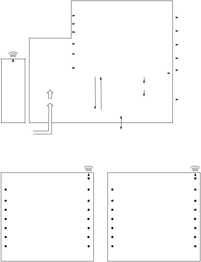
7. CONTROL BLOCK DIAGRAM
7-1. Indoor Unit
|
|
|
|
|
|
Indoor Unit Control Panel |
|
|
|
|||
|
|
|
|
|
|
|
|
M.C.U |
|
|
|
|
|
|
Heat Exchanger Sensor |
|
|
Functions |
|
|
Operation |
||||
|
|
|
|
|||||||||
|
|
|
|
|
|
|
|
|
|
|
|
Display |
|
|
|
|
|
|
|
|
|
|
|
|
|
|
|
Temperature Sensor |
|
|
• Louver Control |
|
|
|
||||
|
|
|
|
|
|
|
|
|
|
|
|
Timer |
Infrared Rays Signal Receiver |
|
|
|
• 3-minute Delay at Restart for Compressor |
|
|
||||||
|
|
|
|
|
Display |
|||||||
|
|
|
||||||||||
|
|
|
|
|
|
|
|
|
|
|
|
|
|
|
|
|
|
|
|
|
|
|
|
|
|
Infrared |
|
Initializing Circuit |
|
|
• Motor Revolution Control |
|
|
ECONO. |
||||
|
|
|
|
|||||||||
|
|
|
|
|
Sign Display |
|||||||
Rays |
|
|
|
|
|
|
|
|
|
|
||
|
Clock Frequency |
|
|
• Processing |
|
|
|
|||||
|
|
|
|
|
|
|
|
|||||
|
|
|
Oscillator Circuit |
|
|
(Temperature Processing) |
|
|
FAN-ONLY |
|||
|
|
|
|
|
|
|
|
• Timer |
|
|
Sign Display |
|
|
|
|
|
|
|
|
|
|
|
|||
|
|
|
|
|
|
|
|
|
|
|
||
|
|
|
|
|
|
|
|
|
|
|
||
|
|
|
|
|
|
|
|
|
|
|
|
|
|
|
|
|
|
|
|
|
• Serial Signal Communication |
|
|
Indoor |
|
|
|
|
|
|
|
|
|
|
||||
|
|
|
|
|
|
|
|
|
|
Fan Motor |
||
|
|
|
|
|
|
|
|
|
||||
|
|
|
|
|
|
|
|
|
|
|
|
|
|
|
|
|
|
|
|
|
|
|
|
|
|
|
|
|
|
|
|
|
|
|
|
|
|
|
|
|
|
Power Supply |
|
|
|
|
|
|
|
||
Remote |
|
Circuit |
|
|
|
Louver ON/OFF Signal |
|
|
|
|||
|
|
|
|
|
|
|
|
|
|
|
||
|
|
|
|
|
|
|
|
|
|
|
||
Control |
|
|
|
|
|
|
|
|
|
|
|
|
|
|
|
|
|
|
|
|
|
|
|
|
Louver |
|
|
|
Noise Filter |
|
|
|
Louver Driver |
|
|
|||
|
|
|
|
|
|
|
|
Motor |
||||
|
|
|
|
|
|
|
|
|
|
|
|
|
|
|
|
|
|
|
|
|
|
|
|
|
|
|
|
|
|
|
|
|
|
|
|
|
|
|
|
|
|
|
|
|
|
|
Serial Signal Transmitter/Receiver |
|
|
|
|
|
|
|
|
|
|
|
|
|
|
|
|
|
From Outdoor Unit |
|
|
|
|
Serial Signal Communication |
|
|
|
|
||||||
|
|
|
|
|
|
|
|
|
|
|
|
|
|
|
|
REMOTE CONTROL |
|
|
|
|
|
|
|
|
|||||||
|
|
|
RAS-M10YKV-E, RAS-M13YKV-E |
|
|
|
|
RAS-M10YKCV-E, RAS-M13YKCV-E |
|
||||||
|
|
|
(Heat pump model) |
|
|
|
(Cooling only model) |
||||||||
|
|
|
|
|
|
Infrared |
|
|
|
|
|
Infrared |
|||
|
|
|
|
|
|
Rays |
|
|
|
|
|
Rays |
|||
|
|
|
Remote Control |
|
|
|
Remote Control |
||||||||
|
|
|
|
|
|
|
|
|
|
|
|
|
|||
|
|
|
Operation (START/STOP) |
|
|
|
|
|
|
Operation (START/STOP) |
|
|
|
||
|
|
|
|
|
|
|
|
||||||||
|
|
|
|
|
|
|
|
|
|
|
|
|
|
||
|
|
|
|
|
|
|
|
|
|
|
|
|
|
||
|
|
|
Operation Mode Selection |
|
|
|
|
|
|
Operation Mode Selection |
|
|
|
||
|
|
|
AUTO, COOL, DRY, HEAT |
|
|
|
|
|
|
AUTO, COOL, DRY, FAN ONLY |
|
|
|
||
|
|
|
|
|
|
|
|
|
|
|
|
|
|
|
|
|
|
|
Thermo. Setting |
|
|
|
|
|
|
Thermo. Setting |
|
|
|
||
|
|
|
|
|
|
|
|
||||||||
|
|
|
|
|
|
|
|
|
|
|
|
|
|
||
|
|
|
|
|
|
|
|
|
|
|
|
|
|
||
|
|
|
Fan Speed Selection |
|
|
|
|
|
|
Fan Speed Selection |
|
|
|
||
|
|
|
|
|
|
|
|
||||||||
|
|
|
|
|
|
|
|
|
|
|
|
|
|
||
|
|
|
|
|
|
|
|
|
|
|
|
|
|
||
|
|
|
ON TIMER Setting |
|
|
|
|
|
|
ON TIMER Setting |
|
|
|
||
|
|
|
|
|
|
|
|
||||||||
|
|
|
|
|
|
|
|
|
|
|
|
|
|
||
|
|
|
|
|
|
|
|
|
|
|
|
|
|
||
|
|
|
OFF TIMER Setting |
|
|
|
|
|
|
OFF TIMER Setting |
|
|
|
||
|
|
|
|
|
|
|
|
||||||||
|
|
|
|
|
|
|
|
|
|
|
|
|
|
||
|
|
|
|
|
|
|
|
|
|
|
|
|
|
||
|
|
|
Louver AUTO Swing |
|
|
|
|
|
|
Louver AUTO Swing |
|
|
|
||
|
|
|
|
|
|
|
|
||||||||
|
|
|
|
|
|
|
|
|
|
|
|
|
|
||
|
|
|
|
|
|
|
|
|
|
|
|
|
|
||
|
|
|
Louver Direction Setting |
|
|
|
|
|
|
Louver Direction Setting |
|
|
|
||
|
|
|
|
|
|
|
|
||||||||
|
|
|
|
|
|
|
|
|
|
|
|
|
|
||
|
|
|
|
|
|
|
|
|
|
|
|
|
|
||
|
|
|
ECONO. |
|
|
|
|
|
|
ECONO. |
|
|
|
||
|
|
|
|
|
|
|
|
||||||||
|
|
|
|
|
|
|
|
|
|
|
|
|
|
|
|
– 25 –

7-2. Outdoor Unit (Inverter Assembly)
RAS-M18YAV-E
CONTROL BLOK DIAGRAM (Outdoor unit)
|
|
|
|
220–230–240 V ~ 50 Hz |
|
|
|
|
|
|
|
|
|
|
|
MCC-775 (SUB P.C.B) |
MCC-758 (MAIN P.C.B) |
|
|
|
|||||
|
|
|
A unit |
B unit |
M.C.U |
|
|
|
Rotor position |
|
|
|
|
|
|
send/receive |
send/receive |
|
|
|
detect circuit |
|
|
||
|
|
|
circuit |
circuit |
PWM synthesis function |
|
|
|
|
|
|
|
|
|
|
|
• |
|
Rotor position |
|
|
|
|||
|
|
|
|
• |
Input current release control |
|
|
|
|
|||
|
|
|
|
|
detect circuit |
|
|
|
||||
|
|
|
|
|
|
|
|
|
|
|
||
|
|
|
|
• |
IGBT over-current detect control |
|
|
|
|
|
||
|
|
|
|
• |
Outdoor fan control |
|
|
|
|
Gate drive |
|
|
|
|
|
|
• |
High power factor correction control |
|
|
circuit |
|
|||
|
Outdoor Heat- |
|
|
|
|
|
|
|
||||
|
|
|
|
|
|
|
|
|
|
|
|
|
|
exchanger |
|
M.C.U |
• Signal communication to MCU |
Over current |
|
|
|
||||
26 – |
temp.sensor |
|
|
|
|
|
detect circuit |
|
|
|
||
Discharge |
• |
Inverter output frequency control |
|
|
|
|
|
|
|
|
||
– |
temp. sensor |
• |
A/D converter function |
|
|
|
|
|
|
|
|
|
|
|
|
|
|
|
|
|
|
|
|||
|
Suction temp. |
• |
P.M.V. control |
|
|
|
|
|
|
|
|
|
|
sensor |
|
|
|
|
|
|
|
|
|
||
|
• |
Discharge temp. control |
High power factor |
Over current |
Gate drive |
|
|
|||||
|
|
|
|
|||||||||
|
|
correction circuit |
detect circuit |
circuit |
|
|
|
|||||
|
Gas side pipe |
|
|
|
|
|
|
|||||
|
• |
Error display |
|
|
|
|
|
|
|
|
|
|
|
temp. sensor |
|
|
|
|
|
|
|
|
|
||
|
|
|
|
|
|
|
|
|
|
|
|
|
|
Outdoor air |
• Signal communication to MCU |
|
|
|
|
|
|
|
|
||
|
|
|
Noise |
Input current |
Converter |
Over current |
Inverter |
Outdoor |
||||
|
temp. sensor |
|
|
|||||||||
|
|
|
|
filter |
Sensor |
(AC |
DC) |
|
sensor |
(DC |
AC) |
fan motor |
|
|
|
Driver circuit of P.M.V. |
|
|
|
|
|
|
|
|
|
|
|
|
|
Relay |
|
|
|
|
|
|
|
|
|
|
|
|
RY04 |
|
|
|
|
|
|
|
|
|
|
|
A unit |
B unit |
|
|
|
Over current |
Inverter |
Compressor |
||
|
|
|
P.M.V. |
P.M.V. |
|
|
|
|
sensor |
(DC |
AC) |
|
|
|
|
|
|
|
|
|
|||||
P.M.V. : Pulse Modulating Valve |
|
|
PWM |
: Pulse Width Modulation |
|
IGBT |
: Insulated Gate Bipolar Transistor |
4 way valve |
Loading...