


Toshiba RAV-164TUH-1-PE, RAV-164TU-1-PE, RAV-134TUH-1-PE, RAV-134TU-1-PE, RAV-104TUH-1-PE SERVICE MANUAL
TOSHIBA
SERVICE MANUAL
FILE NO. A90-0031
AIR-CONDITIONER
SPLIT TYPE, HEAT PUMP COOLING ONLY
WAY CASSETTE TYPE
-104TUH-1-PE -134TUH-1-PE/RAV-134AH-PE -164TUH-1-PE/RAV-164AH-PE -134TU-1-PE/RAV-134A-PE -164TU-1-PE/RAV-164A-PE
Printed in UK NOVEMBER 2000

CONTENTS
1. |
SPECIFICATIONS |
4 |
|
|
|
2. |
CONSTRUCTIONS VIEWS |
7 |
|
|
|
3. |
WIRING DIAGRAMS |
9 |
|
|
|
4. |
SPECIFICATIONS OF ELECTRICAL PARTS |
13 |
|
|
|
5. |
REFRIGERANT PIPING DIAGRAMS |
18 |
|
|
|
6. |
PERFORMANCE CHARACTERISTICS |
23 |
|
|
|
7. |
EXPLODED VIEWS AND PARTS LISTS |
26 |
SUMMARY
The units referred to within this Manual conform with the protection requirements of Directives 89/336/EEC Electromagnetic Compatibility and 73/23/EEC Low Voltage.
Operating conditions of units are as follows:
OUTDOOR |
-2 to 43˚C (COOL) |
|
TEMPERATURE |
||
-10 to 21˚C (HEAT) |
||
|
||
|
|
|
ROOM |
18 to 32˚C (COOL) |
|
TEMPERATURE |
||
15 to 29˚C (HEAT) |
||
|
||
|
|
|
ROOM |
LESS THAN 80% (COOL) |
|
HUMIDITY |
||
|
|
Note 1:
Note 2:
Note 3:
Note 4:
Cooling Capacity is based on the following temperature conditions: Indoor air inlet temperature 27˚C DB, 19˚C WB.
Outdoor air inlet temperature 35˚C DB.
Heating Capacity is based on the following temperature conditions: Indoor air inlet temperature 20˚C DB.
Outdoor air inlet temperature 7˚C DB, 6˚C WB.
For details on Control Circuits, refer to Service Manual A90-9925.
Metric/Imperial pipe conversion:
Diameter (mm) |
6.4 |
9.5 |
12.7 |
15.9 |
19 |
22 |
|
||||||
|
|
|
|
|
|
|
Nominal Diameter (inch) |
1/4 |
3/8 |
1/2 |
5/8 |
3/4 |
7/8 |
|
||||||
|
|
|
|
|
|
|
3

1. SPECIFICATIONS
|
Item |
|
Model |
RAV-104TUH-1-PE |
|
|
|
Cooling capacity |
|
|
kW |
2.5 |
|
|
Heating capacity |
|
|
kW |
2.8 |
|
|
|
|
|
Phase |
1 |
|
|
Power source |
|
|
V |
220-240 |
|
|
|
|
|
Hz |
50 |
|
|
Power consumption |
|
|
kW |
0.07 |
|
|
Power factor |
|
% |
93 |
|
|
|
Running current |
|
|
A |
0.33 |
|
|
Starting current |
|
|
A |
0.6 |
|
|
Operating noise (SPL) |
Indoor Unit (High/Med/Low) |
|
dB(A) |
40/36/34 |
|
|
Refrigerant |
Name of Refrigerant |
|
|
R407C |
|
|
|
Larger side size |
|
mm |
ø12.7 |
|
|
Interconnection |
Coupler style |
|
|
Flare |
|
|
pipe |
Smaller side size |
|
mm |
ø6.4 |
|
|
|
Coupler style |
|
|
Flare |
|
|
Condensate drain pipe diameter |
|
|
mm |
ø25.5 (OD) |
|
|
Appearance colour |
|
|
|
Grey (galvanized steel & thermal insulation) |
|
|
|
Height |
|
mm |
190 |
|
|
Dimensions |
Width |
|
mm |
910 |
|
|
|
Depth |
|
mm |
480 |
|
|
Net weight |
|
|
kg |
23 |
|
|
Heat exchanger type |
|
|
|
Finned tube |
|
|
Indoor fan type |
|
|
|
Transverse flow fan |
|
|
Air volume |
|
|
m3/hr |
550 |
|
|
Fan motor output |
|
|
W |
7 x 2 |
|
|
Ceiling Panel Model |
|
|
|
RBC-U134PG(W)-E |
|
|
Appearance Colour |
|
|
|
Silky white (Munsell 2.9Y8.9/0.8) |
|
|
|
Height |
|
mm |
25 |
|
|
Dimensions |
Width |
|
mm |
1,050 |
|
|
|
Depth |
|
mm |
550 |
|
|
Net Weight |
|
|
kg |
4.5 |
|
|
Air Filter |
|
|
|
Washable |
|
|
|
|
|
|
|
|
Specifications are subject to change without notice
4

1. SPECIFICATIONS
|
Item |
|
Model |
|
RAV-134TUH-1-PE |
RAV-164TUH-1-PE |
|||||
|
|
|
|
|
|
|
|
|
|
|
|
|
Cooling capacity |
|
|
kW |
|
3.6 |
|
4.5 |
|
||
|
Heating capacity |
|
|
kW |
|
4.2 |
|
5.0 |
|
||
|
|
|
|
Phase |
|
1 |
|
1 |
|
|
|
|
Power source |
|
|
V |
|
220-240 |
|
220-240 |
|
||
|
|
|
|
Hz |
|
50 |
|
50 |
|
|
|
|
|
|
|
|
|
COOLING |
|
HEATING |
COOLING |
|
HEATING |
|
Power consumption |
|
|
kW |
|
2.0 |
|
2.15 |
2.2 |
|
2.2 |
|
Power factor |
|
% |
|
88 |
|
90 |
90 |
|
89 |
|
|
Running current |
|
|
A |
|
9.9 |
|
10.4 |
10.6 |
|
10.7 |
|
Starting current |
|
|
A |
|
60 |
|
60 |
|
|
|
|
Operating noise |
Indoor Unit (High, Med, Low) |
|
dB(A) |
|
40/36/34 |
|
41/37/35 |
|
||
|
(SPL) |
Outdoor Unit |
|
dB(A) |
|
50 |
|
50 |
|
|
|
|
|
Name of Refrigerant |
|
|
|
R407C |
|
R407C |
|
||
|
Refrigerant |
Charge Volume |
|
kg |
|
1.05 |
|
1.2 |
|
||
|
|
Add. Volume (20-30m) |
|
g/m |
|
35 |
|
35 |
|
|
|
|
Refrigerant control |
|
|
|
|
Capillary tube & Expansion valve |
Capillary tube & Expansion valve |
||||
|
|
Larger side size |
|
mm |
|
ø12.7 |
|
ø12.7 |
|
||
|
|
Coupler style |
|
|
|
Flare |
|
Flare |
|
||
|
|
Smaller side size |
|
mm |
|
ø6.4 |
|
ø6.4 |
|
||
|
|
Coupler style |
|
|
|
Flare |
|
Flare |
|
||
|
Interconnection |
Standard length |
|
m |
|
7.5 |
|
7.5 |
|
||
|
pipe |
Maximum actual pipe length |
|
|
|
|
|
|
|
|
|
|
|
(of one way) |
|
m |
|
30 |
|
30 |
|
|
|
|
|
Maximum height difference |
|
|
|
|
|
|
|
|
|
|
|
If Indoor Unit higher |
|
m |
|
15 |
|
15 |
|
|
|
|
|
If Outdoor Unit higher |
|
m |
|
30 |
|
30 |
|
|
|
|
Condensate drain pipe diameter |
|
|
mm |
|
ø25.5 (OD) |
|
ø25.5 (OD) |
|
||
|
INDOOR UNIT Model |
|
|
|
|
RAV-134TUH-1-PE |
RAV-164TUH-1-PE |
||||
|
Appearance colour |
|
|
|
|
Grey (galvanized steel & |
Grey (galvanized steel & |
||||
|
|
|
|
|
|
thermal insulator) |
thermal insulator) |
||||
|
|
Height |
|
mm |
|
190 |
|
190 |
|
||
|
Dimensions |
Width |
|
mm |
|
910 |
|
910 |
|
||
|
|
Depth |
|
mm |
|
480 |
|
480 |
|
||
|
Net weight |
|
|
kg |
|
23 |
|
23 |
|
|
|
|
Heat exchanger type |
|
|
|
|
Finned tube |
Finned tube |
||||
|
Indoor fan type |
|
|
|
|
Transverse flow fan |
Transverse flow fan |
||||
|
Air volume |
|
|
m3/h |
|
700 |
|
750 |
|
||
|
Fan motor output |
|
|
W |
|
7 x 2 |
|
7 x 2 |
|
||
|
OUTDOOR UNIT Model |
|
|
|
|
RAV-134AH-PE |
RAV-164AH-PE |
||||
|
Appearance colour |
|
|
|
|
Bronze white (Munsell 6Y7.5/1) |
Bronze white (Munsell 6Y7.5/1) |
||||
|
|
Height |
|
mm |
|
740 |
|
740 |
|
||
|
Dimensions |
Width |
|
mm |
|
880 |
|
880 |
|
||
|
|
Depth |
|
mm |
|
310 |
|
310 |
|
||
|
Net weight |
|
|
kg |
|
61 |
|
61 |
|
|
|
|
Heat exchanger type |
|
|
|
|
Finned tube |
Finned tube |
||||
|
Outdoor fan type |
|
|
|
|
Propeller fan |
Propeller fan |
||||
|
Air flow volume |
|
|
m3/h |
|
2,700 |
|
2,700 |
|
||
|
Fan motor output |
|
|
W |
|
39 |
|
39 |
|
|
|
|
Compressor |
Model |
|
|
|
PG330X3F-4LS |
PG350X3F-4LS |
||||
|
Output |
|
kW |
|
1.5 |
|
1.5 |
|
|||
|
|
|
|
|
|
||||||
|
Protective device |
|
|
|
|
High pressure switch, fuse, crankcase heater, inner overload relay, |
|||||
|
|
|
|
|
|
|
bi-metal thermostat |
|
|||
|
|
|
|
|
|
|
|
|
|||
|
|
|
|
|
|
|
|
||||
|
CEILING PANEL model |
|
|
|
|
RBC-U134PG(W)-E |
RBC-U134PG(W)-E |
||||
|
Appearance colour |
|
|
|
|
Silky white (Munsell 2.9Y8.9/0.8) |
Silky white (Munsell 2.9Y8.9/0.8) |
||||
|
|
Height |
|
mm |
|
25 |
|
25 |
|
|
|
|
Dimensions |
Width |
|
mm |
|
1,050 |
|
1,050 |
|
||
|
|
Depth |
|
mm |
|
550 |
|
550 |
|
||
|
Net weight |
|
|
kg |
|
4.5 |
|
4.5 |
|
||
|
Air filter |
|
|
|
|
Washable |
|
Washable |
|
||
|
|
|
|
|
|
|
|
|
|
|
|
|
|
|
|
|
|
|
|
|
|
|
|
Specifications are subject to change without notice
5

1. SPECIFICATIONS
|
Item |
|
Model |
|
RAV-134TU-1-PE |
RAV-164TU-1-PE |
|
||
|
|
|
|
||||||
|
|
|
|
|
|
|
|
|
|
|
Cooling capacity |
|
|
kW |
|
3.6 |
4.5 |
|
|
|
|
|
|
Phase |
|
1 |
1 |
|
|
|
Power source |
|
|
V |
|
220-240 |
220-240 |
|
|
|
|
|
|
Hz |
|
50 |
50 |
|
|
|
|
|
|
|
|
COOLING |
COOLING |
|
|
|
Power consumption |
|
|
kW |
|
2.0 |
2.2 |
|
|
|
Power factor |
|
% |
|
88 |
90 |
|
|
|
|
Running current |
|
|
A |
|
9.9 |
10.6 |
|
|
|
Starting current |
|
|
A |
|
60 |
60 |
|
|
|
Operating noise |
Indoor Unit (High, Med, Low) |
|
dB(A) |
|
40/36/34 |
41/37/35 |
|
|
|
(SPL) |
Outdoor Unit |
|
dB(A) |
|
50 |
50 |
|
|
|
|
Name of Refrigerant |
|
|
|
R407C |
R407C |
|
|
|
Refrigerant |
Charge Volume |
|
kg |
|
1.05 |
1.2 |
|
|
|
|
Add. Volume (20-30m) |
|
g/m |
|
35 |
35 |
|
|
|
Refrigerant control |
|
|
|
|
Capillary tube |
Capillary tube |
|
|
|
|
Larger side size |
|
mm |
|
ø12.7 |
ø12.7 |
|
|
|
|
Coupler style |
|
|
|
Flare |
Flare |
|
|
|
|
Smaller side size |
|
mm |
|
ø6.4 |
ø6.4 |
|
|
|
|
Coupler style |
|
|
|
Flare |
Flare |
|
|
|
Interconnection |
Standard length |
|
m |
|
7.5 |
7.5 |
|
|
|
pipe |
Maximum actual pipe length |
|
|
|
|
|
|
|
|
|
(of one way) |
|
m |
|
30 |
30 |
|
|
|
|
Maximum height difference |
|
|
|
|
|
|
|
|
|
If Indoor Unit higher |
|
m |
|
15 |
15 |
|
|
|
|
If Outdoor Unit higher |
|
m |
|
30 |
30 |
|
|
|
Condensate drain pipe diameter |
|
|
mm |
|
ø25.5 (OD) |
ø25.5 (OD) |
|
|
|
INDOOR UNIT Model |
|
|
|
|
RAV-134TU-1-PE |
RAV-164TU-1-PE |
|
|
|
Appearance colour |
|
|
|
|
Grey (galvanized steel & |
Grey (galvanized steel & |
|
|
|
|
|
|
|
|
thermal insulator) |
thermal insulator) |
|
|
|
|
Height |
|
mm |
|
190 |
190 |
|
|
|
Dimensions |
Width |
|
mm |
|
910 |
910 |
|
|
|
|
Depth |
|
mm |
|
480 |
480 |
|
|
|
Net weight |
|
|
kg |
|
23 |
23 |
|
|
|
Heat exchanger type |
|
|
|
|
Finned tube |
Finned tube |
|
|
|
Indoor fan type |
|
|
|
|
Transverse flow fan |
Transverse flow fan |
|
|
|
Air volume |
|
|
m3/h |
|
700 |
750 |
|
|
|
Fan motor output |
|
|
W |
|
7 x 2 |
7 x 2 |
|
|
|
OUTDOOR UNIT Model |
|
|
|
|
RAV-134A-PE |
RAV-164A-PE |
|
|
|
Appearance colour |
|
|
|
|
Bronze white (Munsell 6Y7.5/1) |
Bronze white (Munsell 6Y7.5/1) |
|
|
|
|
Height |
|
mm |
|
740 |
740 |
|
|
|
Dimensions |
Width |
|
mm |
|
880 |
880 |
|
|
|
|
Depth |
|
mm |
|
310 |
310 |
|
|
|
Net weight |
|
|
kg |
|
58 |
58 |
|
|
|
Heat exchanger type |
|
|
|
|
Finned tube |
Finned tube |
|
|
|
Outdoor fan type |
|
|
|
|
Propeller fan |
Propeller fan |
|
|
|
Air flow volume |
|
|
m3/h |
|
2,700 |
2,700 |
|
|
|
Fan motor output |
|
|
W |
|
39 |
39 |
|
|
|
Compressor |
Model |
|
|
|
PG330X3F-4LS |
PG350X3F-4LS |
|
|
|
Output |
|
kW |
|
1.5 |
1.5 |
|
|
|
|
|
|
|
|
|
||||
|
Protective device |
|
|
|
|
fuse, crankcase heater |
|
|
|
|
|
|
|
|
|
|
|
|
|
|
CEILING PANEL model |
|
|
|
|
RBC-U134PG(W)-E |
RBC-U134PG(W)-E |
|
|
|
Appearance colour |
|
|
|
|
Silky white (Munsell 2.9Y8.9/0.8) |
Silky white (Munsell 2.9Y8.9/0.8) |
|
|
|
|
Height |
|
mm |
|
25 |
25 |
|
|
|
|
|
|
|
|
|
|
||
|
Dimensions |
Width |
|
mm |
|
1,050 |
1,050 |
|
|
|
|
Depth |
|
mm |
|
550 |
550 |
|
|
|
Net weight |
|
|
kg |
|
4.5 |
4.5 |
|
|
|
Air filter |
|
|
|
|
Washable |
Washable |
|
|
|
|
|
|
|
|
|
|
|
|
|
|
|
|
|
|
|
|
|
|
Specifications are subject to change without notice
6
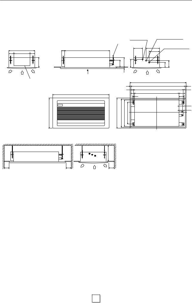
2. CONSTRUCTION VIEWS
2.1Indoor Unit RAV-104TUH-1-PE RAV-134TUH-1-PE RAV-164TUH-1-PE RAV-134TU-1-PE RAV-164TU-1-PE
|
Drain pipe joint |
Refrigerant piping joint |
|
|
(Liquid ø6.4) |
||
Hanger bolt |
(outer ø25.5) |
||
|
|||
|
|
|
|
|
70 |
(4-M10) |
|
|
480 |
|
840 |
|
|
|
|
|
|
||
76 |
330 |
76 |
|
|
|
|
|
190 |
|
190 |
156 |
|
|
|
|
25 |
|
Refrigerant piping joint |
|
(Gas ø12.7) |
|
96 |
131 |
Wiring connection |
A |
|
|
TOSHIBA
550
|
|
|
|
Panel outer dimension 1050 |
|
|
|
|
20 |
Ceiling opening 1010 |
20 |
|
|
|
40 |
Hang bolt pitch 930 |
40 |
1050 |
|
|
70 |
840 |
110 |
|
|
40 |
|
90 |
|
dimensionouterPanel550 |
510openingCeiling |
|
|
||
480 |
410pitchboltHang |
|
66 |
||
|
|
|
|
|
|
|
|
|
|
|
73 |
View A
600 |
600 |
Minimum |
Minimum |
200
(Unit: mm)
600 Minimum
Space required for service and installation
7

2. CONSTRUCTION VIEWS
2.2Outdoor Unit RAV-134AH-PE RAV-164AH-PE RAV-134A-PE
RAV-164A-PE Knock-out hole for drain
|
Hole for drain |
|
|
|
|
(2xø19 hole) |
360 |
|
|
|
165 |
|
|
|
|
|
|
Refrigerant pipe connection |
|
12 |
117 |
40 |
280 |
|
|
(Gas ø12.7) |
|||
|
|
|||
70 |
30 |
70 50 |
340 |
|
Refrigerant pipe connection |
|
|
|
|
|
(Liquid ø6.4) |
12 |
45 |
50 |
45 |
Earth screw (M6) |
|
790 |
|||||
|
|
Anchor bolt hole |
Air outlet |
Electric |
Terminal cover |
(4-12x18slots) |
parts box |
|
|
|
|
|
|
|
880 |
310 |
104 |
|
Handle |
|
|
|
(Both sides) |
|
500 |
|
|
|
|
|
|
740 |
380 |
|
90 |
|
|
|
|
|
|
|
88 |
18 |
|
|
|
|
|
320 |
|
|
37 |
566 |
Blow out guide |
364 |
mounting hole |
|
||
|
|
|
|
|
|
(4-ø3 embosses) |
|
|
|
Space required for service |
|
100 |
100 |
500 |
|
||
Outlet |
|
(Space for wiring |
|
|
and piping) |
When installed with the inlet facing the wall
(Space for wiring and piping)
100 |
300 |
500 |
|
Outlet |
|
|
|
When installed with the outlet facing the wall
8

3. WIRING DIAGRAMS
3.1RAV-104TUH-1-PE RAV-134TUH-1-PE RAV-164TUH-1-PE
|
|
|
TA |
|
TC |
|
|
|
|
|
|
GRY |
2 |
2 |
CN04 |
|
CN05 |
|
|
|
|
15 15 |
|
GRY |
CN15 (TA) |
|
(TC) |
|
|
|
|
14 14 |
|||
|
1 |
1 |
(LAN) |
|
CN07 |
|
|
|
13 13 |
||
|
|
|
|
|
|
|
|
12 12 |
|||
ORG |
1 |
1 |
|
|
(FAN) |
|
|
|
|||
YEL |
|
|
H |
1 1 BLK |
|
|
11 11 |
||||
2 2 |
|
RY04 |
|
|
10 10 |
||||||
BLU |
3 |
3 |
|
|
M |
|
ORG |
|
|
9 |
9 |
CN02 |
|
|
|
|
|
|
|||||
|
|
REMOCON |
|
|
3 |
3 |
|
|
8 |
8 |
|
|
|
|
RY03 |
|
|
|
|||||
|
|
|
|
9 9 RED |
|
|
2 |
2 |
|||
|
|
|
|
|
L |
5 |
5 BLU |
|
|
7 |
7 |
CN12 |
|
|
|
RY02 |
UL |
7 |
7 YEL |
|
|
5 |
5 |
|
|
|
|
|
|
|
4 |
4 |
|||
|
|
|
|
|
|
|
|
|
|
3 |
3 |
CN01 |
|
|
|
|
|
|
|
RY01 |
|
1 |
1 |
|
|
|
|
|
|
|
(output) |
|
|||
(TRANS) |
|
|
|
|
|
|
|
|
|
||
|
|
|
CN21 |
|
|
|
|
|
|
||
ORG |
4 |
4 |
|
|
|
|
CN09 |
|
|
|
|
BLU |
|
|
|
|
|
|
|
|
|||
3 |
3 |
|
|
|
|
|
BLK |
BLK |
|
||
BLK |
|
|
|
|
|
(WHI) |
|
||||
2 |
2 |
|
|
|
|
|
|
||||
YEL |
1 |
1 |
|
|
|
|
|
(LOUVER) |
|
|
|
|
|
|
|
|
|
|
|
|
|||
|
|
|
|
|
|
|
|
|
|
||
WHI
|
3 |
3 |
|
|
|
|
|
|
|
|
1 |
1 |
RY01 |
|
RY06 |
|
|
|
RY07 |
TR |
RED |
|
|
|
|
|
|
|
|
|
|
|
|
|
|
F (L1) |
|
CN03 |
|
|
|
|
|
|
|
|
|
||
|
|
|
CN10 |
|
|
|
(N) |
(SERIAL) |
|
|
|
|
(PUMP) 7 |
5 |
3 |
1 |
1 |
3 |
5 |
|
|
|
7 |
5 |
3 |
1 |
1 |
3 |
5 |
GRY |
RED |
PUR |
GRY |
RED |
GRY |
BLK |
WHI
4 |
6 |
5 |
1 |
2 |
3 |
WHI |
RC01 |
|
|||||||
4 |
6 |
5 |
1 |
2 |
3 |
|
|
|
|
|
|
|
|
|
RC02 |
GRN/YEL
Indoor unit |
1 |
2 |
3 |
X Y A B C
DM
CS
F3 |
Interface |
|
PCB |
TR
|
|
|
SM |
SM |
|
|
|
01 |
02 |
|
RED |
|
|
|
|
WHI |
|
WHI |
FM |
|
1 |
1 |
||
|
2 |
2 |
|
02 |
|
3 |
3 |
RED |
|
|
|
|||
|
4 |
4 |
|
YEL |
|
5 |
5 |
|
|
|
|
BLU |
||
|
6 |
6 |
|
|
|
|
ORG |
||
|
|
|
|
|
|
|
|
|
BLK |
|
RED |
|
|
|
WHI |
1 |
1 |
WHI |
FM |
|
||||
|
2 |
2 |
|
01 |
|
3 |
3 |
RED |
|
|
4 |
4 |
YEL |
|
|
5 |
5 |
|
|
|
|
BLU |
||
|
6 |
6 |
|
|
|
|
ORG |
||
|
|
|
|
|
|
|
|
|
BLK |
|
|
|
|
1 |
2 |
3 |
|
|
|
|
|
|
|
(1 Phase |
|
|
|
|
|
|
|
|
|
|
model) |
F2 |
|
|
|
|
|
|
|
|
|
Earth |
|
|
|
|
|
||
|
|
|
|
|
|
|
|
|
||
|
|
|
Screw |
|
|
|
|
|
|
|
X Y |
A |
B C |
|
L |
N |
|
|
|
|
|
|
|
|
|
|
|
|
|
|||
Central |
Remote |
|
|
Power |
|
|
|
|
||
Remote |
Controller |
Outdoor |
|
Supply |
|
|
|
|
||
Controller |
|
220/240V |
|
|
|
|
||||
(Optional) |
|
|
|
|
|
|||||
(Optional) |
unit |
|
~50Hz |
|
|
|
|
|||
|
|
|
|
|
|
|
||||
|
|
|
|
|
|
|
|
|||
|
|
|
|
|
|
Symbol |
Name |
Symbol |
Name |
|
|
|
|
|
|
|
FM01, 02 |
Fan Motor |
F |
Fuse (PCB) |
|
|
|
|
|
|
|
RC01,02 |
Running Capacitor |
F3 |
Fuse (Interface) PCB |
|
Shows terminal block and figures show terminal numbers. |
TR |
Transformer |
DM |
Drain Pump |
||||||
TA |
Sensor |
SM01, 02 |
Stepper Motor |
|||||||
Broken lines show wiring at site. |
|
|
||||||||
|
|
TC |
Sensor |
CS |
Float Switch |
|||||
|
|
|
|
|
|
|||||
Do not operate the units with the magnetic contactor pushed in. |
RY01~RY07 Relay |
|
|
|||||||
9

3. WIRING DIAGRAMS
3.2RAV-134TU-1-PE RAV-164TU-1-PE
TA
 TC
TC
|
|
|
CN04 |
|
|
|
|
(TA) |
|
ORG |
1 |
1 |
|
|
YEL |
|
|||
2 |
2 |
|
||
BLU |
|
|||
3 |
3 |
RY02 |
||
CN02 |
REMOCON |
RY03 |
CN12
ORG |
7 |
7 |
|
BLU |
|
||
6 |
6 |
|
|
|
|
||
|
5 |
5 |
CN01 |
|
4 |
4 |
|
|
(TRANS) |
||
BLK |
3 |
3 |
|
2 |
2 |
|
|
YEL |
|
||
1 |
1 |
|
|
|
|
||
|
WHI |
|
|
CN05
(TC)
CN07
(FAN)
H 1 1 BLK
M |
ORG |
|
3 |
||
3 |
L 5 5 BLU
7 |
7 |
YEL |
9 |
9 |
RED |
15 15 |
|
14 14 |
|
13 13 |
|
12 12 |
|
11 11 |
|
10 10 |
|
9 |
9 |
8 |
8 |
7 |
7 |
6 |
6 |
5 |
5 |
4 |
4 |
3 |
3 |
2 |
2 |
1 |
1 |
RY01 |
CN09 |
BLK |
BLK |
(output) |
(WHI) |
||
|
(LOUVER) |
|
|
3 |
3 |
|
|
|
1 |
1 |
|
RY14 |
RY07 |
RY01 |
RY11 |
RED
TR |
|
|
|
F (L1) |
|
|
CN03 |
CN11 |
||
CN10 |
|
|
|
(N) |
|
(FLOAT) |
||||
(PUMP) |
5 |
3 |
1 |
1 |
3 |
5 |
7 |
|
1 |
3 |
|
5 |
3 |
1 |
1 |
3 |
5 |
7 |
|
1 |
3 |
|
6 |
|
|
|
4 |
2 |
8 |
43 |
7 |
3 |
43 |
|
43 5
1
WHI
1 |
2 |
3 |
4 |
5 |
6 |
WHI |
RC02 |
|
|||||||
1 |
2 |
3 |
4 |
5 |
6 |
|
|
|
|
||||||
|
|
|
|
|
|
|
RC01 |
GRN/YEL
Indoor unit |
1 |
2 |
3 |
DM
CS
F3 |
Interface |
|
PCB |
TR
|
|
|
SM |
SM |
|
|
|
01 |
02 |
|
RED |
|
|
|
|
WHI |
|
WHI |
FM |
|
1 |
1 |
||
|
2 |
2 |
|
02 |
|
3 |
3 |
RED |
|
|
|
|||
|
4 |
4 |
|
YEL |
|
5 |
5 |
|
|
|
|
BLU |
||
|
6 |
6 |
|
|
|
|
ORG |
||
|
|
|
|
|
|
|
|
|
BLK |
|
RED |
|
|
|
WHI |
1 |
1 |
WHI |
FM |
|
||||
|
2 |
2 |
|
01 |
|
3 |
3 |
RED |
|
|
4 |
4 |
YEL |
|
|
5 |
5 |
|
|
|
|
BLU |
||
|
6 |
6 |
|
|
|
|
ORG |
||
|
|
|
|
|
|
|
|
|
BLK |
A |
B |
|
C |
|
|
|
|
|
1 |
2 |
3 |
|
|
|
(1 Phase |
|
|
|
|
|
model) |
|
|
|
|
|
F2 |
|
|
|
|
|
Earth |
|
|
|
|
|
screw |
|
|
A |
B |
C |
L |
|
N |
Remote |
|
|
Power |
|
|
Controller |
|
supply |
|
||
(Optional) |
Outdoor |
220/240V |
|
||
|
|
|
~50Hz |
|
|
|
|
|
unit |
|
|
|
|
|
Symbol |
Name |
Symbol |
Name |
|
|
|
FM01, 02 |
Fan Motor |
F |
Fuse (PCB) |
|
|
|
RC01, 02 |
Running Capacitor |
F3 |
Fuse (Interface) PCB |
|
show terminal numbers. |
TR |
Transformer |
DM |
Drain Pump |
|
|
|
|
|
|
||
Shows terminal block and figures |
TA |
Sensor |
SM01, 02 |
Stepper Motor |
||
Broken lines show wiring at site. |
|
|
||||
|
|
TC |
Sensor |
CS |
Float Switch |
|
|
|
|
||||
Do not operate the units with the magnetic contactor pushed in. |
|
RY01~RY14 |
Relay |
43 |
Relay |
|
10
 Loading...