


 Loading...
|
|
|
|
Heat Pump Model |
Cooling Only Model |
||
RAS-M10YDV-E RAS-M10YDCV-E
RAS-M13YDV-E RAS-M13YDCV-E
RAS-M16YDV-E RAS-M16YDCV-E
R410A
PRINTED IN JAPAN, Jul., 2002 ToMo
|
CONTENTS |
|
APPLICATION ......................................................................................................................... |
2 |
|
1. |
PRECAUTIONS FOR SAFETY........................................................................................ |
3 |
2. |
SPECIFICATIONS ........................................................................................................... |
5 |
3. |
CONSTRUCTION VIEWS ................................................................................................ |
7 |
4. |
WIRING DIAGRAM .......................................................................................................... |
8 |
5. |
SPECIFICATIONS OF ELECTRICAL PARTS ................................................................. |
9 |
6. |
REFRIGERANT CYCLE DIAGRAM .............................................................................. |
10 |
7. |
CONTROL BLOCK DIAGRAM ...................................................................................... |
11 |
8. |
OPERATION DESCRIPTION ......................................................................................... |
12 |
9. |
INSTALLATION PROCEDURE ...................................................................................... |
22 |
10. |
DRAIN-UP KIT ............................................................................................................... |
37 |
11. |
WIRED REMOTE CONTROLLER ................................................................................. |
41 |
12. |
HOW TO DIAGNOSE THE TROUBLE ............................................................................ |
45 |
13. |
HOW TO REPLACE THE MAIN PARTS ........................................................................ |
57 |
14. |
EXPLODED VIEWS AND PARTS LIST ......................................................................... |
59 |
|
|
|
APPLICATION |
|
|
|
||
1. Combination List of Indoor/Outdoor Units (¡: Possible |
× |
: Impossible) |
|
|
|
|||
|
Indoor unit |
Heat Pump Model |
RAS- |
Cooling Only Model |
RAS- |
|||
Outdoor unit |
|
M10YDV-E M13YDV-E |
M16YDV-E |
M10YCDV-E M13YCDV-E M16YCDV-E |
||||
Heat Pump |
4M27YAV-E |
¡ |
¡ |
|
¡ |
× |
× |
× |
Model |
3M26YAV-E |
¡ |
¡ |
|
¡ |
× |
× |
× |
RAS- |
M18YAV-E |
¡ |
¡ |
|
× |
× |
× |
× |
|
|
|||||||
Cooling Only |
4M27YACV-E |
× |
× |
|
× |
¡ |
¡ |
¡ |
Model |
3M23YACV-E |
× |
× |
|
× |
¡ |
¡ |
¡ |
RAS- |
M18YACV-E |
× |
× |
|
× |
¡ |
¡ |
× |
|
|
|||||||
2. File No. List of Reference Service Manual (Outdoor Units of Multi Air Conditioner)
Outdoor unit |
Reference Service Manual |
||
|
|
|
|
Heat Pump |
4M27YAV-E |
File No. A01-0004 |
|
|
|
||
Model |
3M26YAV-E |
File No. A01-0004 |
|
RAS- |
|
|
|
M18YAV-E |
File No. A00-9906 |
||
|
|||
|
|
|
|
Cooling Only |
4M27YACV-E |
File No. A01-0004 |
|
|
|
||
Model |
3M23YACV-E |
File No. A01-0002 |
|
RAS- |
|
|
|
M18YACV-E |
File No. A00-9906 |
||
|
|||
|
|
|
|
3.For the details of the specifications of each indoor/outdoor unit to be combined, refer to the next page and after pages with the above service manuals.
4. Optional Parts List
Product name |
Model name |
|
|
Drain-up kit |
RB-F81E |
|
|
Wired remote controller |
RBC-SH-A1LE |
|
|
– 2 –

1. PRECAUTIONS FOR SAFETY
For general public use
Power supply cord of Outdoor unit shall be more than 2.5mm² (H07RN-F or 245 IEC66) polychloroprene
sheathed flexible cord.
•Read this “Precautions for Safety” carefully before servicing.
•The precautions described below include the important items regarding safety. Observe them without fail.
•After the servicing work, perform a trial operation to check for any problem.
•Turn off the main power supply switch (or breaker) before the unit maintenance.
CAUTION New Refrigerant Air Conditioner Servicing
•THIS AIR CONDITIONER ADOPTS THE NEW HFC REFRIGERANT (R410A) WHICH DOES NOT DESTROY OZONE LAYER.
The characteristics of R410A refrigerant is easy to absorb water, oxidizing membrane or oil, and its pressure is approx. 1.6 times of refrigerant R22. Accompanied with adoption of the new refrigerant, refrigerating oil has been also changed. Therefore, during servicing work, be sure that water, dust, former refrigerant, or refrigerating oil does not enter into the refrigerating cycle of new refrigerant air conditioner.
To prevent from mixing of refrigerant and refrigerating oil, the sizes of connecting sections of charging port of the main unit or installation tools are different from those for the conventional refrigerant.
Accordingly, the exclusive tools are required for the new refrigerant (R410A).
For connecting pipes, use new and clean piping materials with high pressure-tight force, which were made for R410A only, so that water or dust does not enter. Moreover, do not use the existing piping because there are problems about pressure-tight force and impurity it.
CAUTION To Disconnect the Appliance from the Main Power Supply.
This appliance must be connected to the main power supply by means of a circuit breaker or a switch with a contact separation of at least 3 mm.
If this is not possible, a power supply plug with grounding must be used. This plug must be easily accessible after installation. The plug must be disconnected from the power supply socket in order to disconnect the appliance completely from the mains.
The installation fuse (25A D type  ) must be used for the power supply line of this conditioner.
 WARNINGS
•Ask an authorized dealer or qualified installation professional to install/maintain the air conditioner.
Inappropriate servicing may result in water leakage, electric shock or fire.
•Turn off the main power supply switch or breaker before attempting any electrical work.
Make sure all power switches are off. Failure to do so may cause electric shock.
•Connect the connecting cable correctly.
If the connecting cable is connected by wrong way, electric parts may be damaged.
•When moving the air-conditioner for installing it in another place again, be very careful not to get the specified refrigerant with any other gaseous body into the refrigeration cycle.
If air or any other gas is mixed in the refrigerant, the gas pressure in the refrigeration cycle becomes abnormally high and it resultingly causes burst of the pipe and injuries on persons.
–3 –

•Never modify this unit by removing any of the safety guards or by by-passing any of the safety interlock switches.
•Exposure of unit to water or other moisture before servicing may cause a short circuit.
Do not store it in a wet basement or expose to rain or water.
•After unpacking the unit, examine it carefully for possible damage.
•Do not install in a place that can increase the vibration of the unit.
•To avoid personal injury, be careful when handling parts with sharp edges.
•Perform installation work properly according to the Installation Manual.
Inappropriate installation may result in water leakage, electric shock or fire.
•When installing the air conditioner in a small room, provide appropriate measures to ensure that the concentration of refrigerant in the room does not exceed the critical level should leakage occur.
It is not dangerous refrigerant; it has not toxicity or combustibility. However, a concentration above 0.3kg/m³ as criterion still causes suffocation. The volume of refrigerant charged to the Multi System air conditioner is more than the volume charged to a conventional individual system.
•Install the air conditioner securely in a location where the weight of the unit can be sustained adequately.
•Perform the specified installation work to guard against an earthquake.
If the air conditioner is not installed appropriately, accidents may occur due to the falling unit.
•If refrigerant gas has leaked during the servicing work, ventilate the room immediately.
If the leaked refrigerant gas comes in contact with fire, noxious gas may generate.
•After the installation work, confirm that refrigerant gas does not leak.
If refrigerant gas leaks into the room and flows near a fire source, such as a cooking range, noxious gas may generate.
•The electrical work must be performed by a qualified electrician in accordance with the Installation Manual. Make sure the air conditioner uses an exclusive circuit.
An insufficient circuit capacity or inappropriate installation may cause fire.
•When wiring, use the specified cables and connect the terminals securely to prevent external forces applied to the cable from affecting the terminals.
•Be sure to provide grounding.
Do not connect ground wires to gas pipes, water pipes, lightning rods or ground wires for telephone cables.
•Conform to the regulations of the local electric company when wiring the power supply.
Inappropriate grounding may cause electric shock.
•Do not install the air conditioner in a location subject to a risk of exposure to combustible gas.
Otherwise, the combustible gas leaks, stays around the unit and a fire may occur.
– 4 –
2. SPECIFICATIONS
RAS-M10YDV-E, RAS-M13YDV-E, RAS-M16YDV-E (Heat Pump Model)
Indoor unit model name |
|
RAS-M10YDV-E |
|
|
RAS-M13YDV-E |
RAS-M16YDV-E |
|
|
|
|
|
|
|
|
|
Cooling capacity |
|
(kW) |
2.7 |
|
|
3.7 |
4.5 |
|
|
|
|
|
|
|
|
Cooling capacity range |
|
(kW) |
*1 |
|
|
*1 |
*1 |
Heating capacity |
|
(kW) |
4.0 |
|
|
5.0 |
5.5 |
|
|
|
|
|
|
|
|
Heating capacity range |
|
(kW) |
*1 |
|
|
*1 |
*1 |
Power supply |
|
(Ø-V-Hz) |
1Ø |
220 – 240 V, 50 Hz / 220 V, 60 Hz |
|||
|
|
|
|
|
|
|
|
Electric characteristics |
Operation current |
(A) |
|
0.59 |
|
||
|
|
|
|
|
|
|
|
Power consumption |
(W) |
|
110 |
|
|||
*2 |
|
|
|||||
|
|
|
|
|
|
|
|
Power factor |
(%) |
|
81 |
|
|||
|
|
|
|||||
|
|
|
|
|
|
|
|
|
Blower |
|
|
|
|
Multi-blade blower |
|
|
|
|
|
|
|
|
|
|
Blower motor output |
(W) |
|
60 |
|
||
|
|
|
|
|
|
|
|
|
Blower speed |
|
5 (Low, Low+, Med, Med+, High) |
||||
|
|
|
|
|
|
|
|
Blower unit |
Air flow (Cooling High *3) |
(m³/h) |
720 |
|
780 |
780 |
|
Air flow (Heating High *3) |
(m³/h) |
720 |
|
780 |
780 |
||
|
|
||||||
|
External static pressure |
(Pa) |
54.9 |
|
63.7 |
63.7 |
|
|
(Upper limit) |
|
(5.6 mmAq) |
|
|
(6.5 mmAq) |
(6.5 mmAq) |
|
|
|
|
|
|
|
|
|
External static pressure |
(Pa) |
35.3 |
|
41.2 |
41.2 |
|
|
(Standard) |
|
(3.6 mmAq) |
|
|
(4.2 mmAq) |
(4.2 mmAq) |
|
|
|
|
|
|
|
|
|
Cooling (high) |
(dB) |
31 |
|
32 |
33 |
|
|
|
|
|
|
|
|
|
|
Cooling (Medium) |
(dB) |
27 |
|
28 |
29 |
|
|
|
|
|
|
|
|
|
Sound level *4 |
Cooling (Low) |
(dB) |
23 |
|
24 |
25 |
|
|
|
|
|
|
|
|
|
Heating (high) |
(dB) |
32 |
|
33 |
34 |
||
|
|
||||||
|
|
|
|
|
|
|
|
|
Heating (Medium) |
(dB) |
28 |
|
29 |
30 |
|
|
|
|
|
|
|
|
|
|
Heating (Low) |
(dB) |
24 |
|
25 |
26 |
|
|
|
|
|
|
|
|
|
|
Height |
(mm) |
|
750 |
|
||
|
|
|
|
|
|
|
|
Dimension |
Width |
(mm) |
|
230 |
|
||
|
|
|
|
|
|
|
|
|
Depth |
(mm) |
|
440 |
|
||
|
|
|
|
|
|
|
|
Net weight |
|
(kg) |
|
19 |
|
||
|
|
|
|
|
|
|
|
Connecting type |
|
|
|
|
|
Full Operation |
|
|
|
|
|
|
|
|
|
Connecting pipe |
Liquid side |
(mm) |
Ø6.35 |
|
Ø6.35 |
Ø6.35 |
|
|
|
|
|
|
|
|
|
Gas side |
(mm) |
Ø9.52 |
|
|
Ø9.52 |
Ø12.7 |
|
|
|
||||||
|
|
|
|
|
|
|
|
Refrigerant |
|
|
|
|
|
R410A |
|
|
|
|
|
|
|
|
|
Wiring connection |
Interconnection |
|
|
|
|
4 wires : includes earth |
|
|
|
|
|
|
|
|
|
Usable temperature range |
(°C) |
|
|
|
21 – 32 / 0 – 28 |
|
|
|
|
|
|
|
|
|
|
|
Wireless remote controller |
|
|
1 |
|
||
|
|
|
|
|
|
|
|
|
Remote controller holder |
|
|
1 |
|
||
|
|
|
|
|
|
|
|
|
Mounting screws |
|
|
|
|
2 (Ø3.5 x 16 L) |
|
|
|
|
|
|
|
|
|
|
Drain hose |
|
|
1 |
|
||
|
|
|
|
|
|
|
|
Accessory |
Elbow thermal-insulation cover |
|
1 |
|
|||
|
|
|
|
|
|
|
|
Batteries (Manganese) |
|
|
2 |
|
|||
|
|
|
|
||||
|
|
|
|
|
|
|
|
|
Black screws |
|
|
2 |
|
||
|
|
|
|
|
|
|
|
|
Tapping screws |
|
|
16 |
|
||
|
|
|
|
|
|
|
|
|
Owner’s manual |
|
|
1 |
|
||
|
|
|
|
|
|
|
|
|
Installation manual |
|
|
1 |
|
||
|
|
|
|
|
|
|
|
*1 : Refer to the service manual of the outdoor unit to be combined.
*2 : Electrical characteristics at High fan speed under standard static pressure.
*3 : Airflow volume at standard static pressure.
*4 : Sound levels at standard static pressure are measured under the conditions specified by JIS B 8616.
Notes :
•For performance when each indoor unit combined with other unit, refer to the service manual of outdoor unit.
•The specification may be subject to change without notice for purpose of improvement.
–5 –
RAS-M10YDCV-E, RAS-M13YDCV-E, RAS-M16YDCV-E (Cooling Only Model)
Indoor unit model name |
|
RAS-M10YDCV-E |
RAS-M13YDCV-E |
RAS-M16YDCV-E |
||
|
|
|
|
|
|
|
Cooling capacity |
|
(kW) |
2.7 |
|
3.7 |
4.5 |
|
|
|
|
|
|
|
Cooling capacity range |
|
(kW) |
*1 |
|
*1 |
*1 |
Power supply |
|
(Ø-V-Hz) |
1Ø |
220 – 240 V, 50 Hz / 220 V, 60 Hz |
||
|
|
|
|
|
|
|
Electric characteristics |
Operation current |
(A) |
|
|
0.59 |
|
|
|
|
|
|
|
|
Power consumption |
(W) |
|
|
110 |
|
|
*2 |
|
|
|
|||
|
|
|
|
|
|
|
Power factor |
(%) |
|
|
81 |
|
|
|
|
|
|
|||
|
|
|
|
|
|
|
|
Blower |
|
|
|
Multi-blade blower |
|
|
|
|
|
|
|
|
|
Blower motor output |
(W) |
|
|
60 |
|
|
|
|
|
|
|
|
|
Blower speed |
|
|
5 (Low, Low+, Med, Med+, High) |
||
|
|
|
|
|
|
|
Blower unit |
Air flow (Cooling High *3) |
(m³/h) |
720 |
|
780 |
780 |
|
External static pressure |
(Pa) |
54.9 |
|
63.7 |
63.7 |
|
(Upper limit) |
|
(5.6 mmAq) |
|
(6.5 mmAq) |
(6.5 mmAq) |
|
|
|
|
|
|
|
|
External static pressure |
(Pa) |
35.3 |
|
41.2 |
41.2 |
|
(Standard) |
|
(3.6 mmAq) |
|
(4.2 mmAq) |
(4.2 mmAq) |
|
|
|
|
|
|
|
|
Cooling (high) |
(dB) |
31 |
|
32 |
33 |
Sound level *4 |
|
|
|
|
|
|
Cooling (Medium) |
(dB) |
27 |
|
28 |
29 |
|
|
Cooling (Low) |
(dB) |
23 |
|
24 |
25 |
|
|
|
|
|
|
|
|
Height |
(mm) |
|
|
750 |
|
|
|
|
|
|
|
|
Dimension |
Width |
(mm) |
|
|
230 |
|
|
|
|
|
|
|
|
|
Depth |
(mm) |
|
|
440 |
|
|
|
|
|
|
|
|
Net weight |
|
(kg) |
|
|
19 |
|
|
|
|
|
|
|
|
Connecting type |
|
|
|
|
Full Operation |
|
|
|
|
|
|
|
|
Connecting pipe |
Liquid side |
(mm) |
Ø6.35 |
|
Ø6.35 |
Ø6.35 |
|
|
|
|
|
|
|
Gas side |
(mm) |
Ø9.52 |
|
Ø9.52 |
Ø12.7 |
|
|
|
|||||
|
|
|
|
|
|
|
Refrigerant |
|
|
|
|
R410A |
|
|
|
|
|
|
|
|
Wiring connection |
Interconnection |
|
|
|
4 wires : includes earth |
|
|
|
|
|
|
|
|
Usable temperature range |
(°C) |
|
|
21 – 32 |
|
|
|
|
|
|
|
|
|
|
Wireless remote controller |
|
|
|
1 |
|
|
|
|
|
|
|
|
|
Remote controller holder |
|
|
|
1 |
|
|
|
|
|
|
|
|
|
Mounting screws |
|
|
|
2 (Ø3.5 x 16 L) |
|
|
|
|
|
|
|
|
|
Drain hose |
|
|
|
1 |
|
|
|
|
|
|
|
|
Accessory |
Elbow thermal-insulation cover |
|
|
1 |
|
|
|
|
|
|
|
|
|
Batteries (Manganese) |
|
|
|
2 |
|
|
|
|
|
|
|
||
|
|
|
|
|
|
|
|
Black screws |
|
|
|
2 |
|
|
|
|
|
|
|
|
|
Tapping screws |
|
|
|
16 |
|
|
|
|
|
|
|
|
|
Owner’s manual |
|
|
|
1 |
|
|
|
|
|
|
|
|
|
Installation manual |
|
|
|
1 |
|
|
|
|
|
|
|
|
*1 : Refer to the service manual of the outdoor unit to be combined.
*2 : Electrical characteristics at High fan speed under standard static pressure.
*3 : Airflow volume at standard static pressure.
*4 : Sound levels at standard static pressure are measured under the conditions specified by JIS B 8616.
Notes :
•For performance when each indoor unit combined with other unit, refer to the service manual of outdoor unit.
•The specification may be subject to change without notice for purpose of improvement.
– 6 –
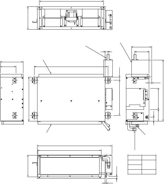
3. CONSTRUCTION VIEWS
650 (Inside flange)
228 (Inside flange)
Drain-up kit
RB-F81E
Drain piping connecting port (Accessory sold separately)
(Nominal Ø20 Vinyl chloride pipe)
200
31 |
142 |
Duct connecting flange
(Require at site)
230
156.5 |
730 (Hanging bolt pitch) |
29.7
|
|
|
24.5 |
|
440 |
350 |
(Hanging bolt pitch) |
211 |
612 |
|
|
40 |
118 |
|
|
Duct connecting flange |
|
(Require at site) |
|
750 |
|
640 (Inside flange) |
216.2 (Inside flange) |
19.7 |
|
13 |
Refrigerant pipe connecting port (Liquid side Ø6.35)
Gas side D
Model D
M10
Ø9.52
M13
M16 Ø12.7
– 7 –

4. WIRING DIAGRAM
|
|
|
|
|
|
4 |
|
|
|
|
|
|
|
|
|
|
1 |
1 |
WHI |
|
|
|
|
|
|
INFRARED RAYS |
BLK |
|
|
|
|
|
|
|||||
2 |
2 |
|
|
|
|
|
|
|||||
RECEIVING AND |
3 |
3 |
RED |
|
|
|
|
|
|
|||
BLU |
|
|
|
|
|
|
||||||
INDICATING PARTS 4 |
4 |
|
|
|
|
|
|
|||||
BLU |
|
|
|
|
|
|
||||||
|
|
|
|
5 |
5 |
|
|
|
|
|
|
|
|
|
1 |
|
|
|
1 |
2 |
3 |
4 |
5 |
1 |
2 |
|
|
|
|
|
1 |
2 |
3 |
4 |
5 |
1 |
2 |
|
BOARDP.C.SWITCH 605-MCC |
|
|
|
|
|
|
CN11 |
|
CN17 |
|||
9 |
9 |
BLK |
9 |
9 |
|
|
|
|
|
|
|
|
|
WHI |
|
|
|
|
|
|
|
||||
|
8 |
8 |
8 |
8 |
|
|
|
|
|
|
|
|
|
GRY |
|
|
|
|
|
|
|
||||
|
7 |
7 |
7 |
7 |
|
|
|
|
|
|
|
|
|
GRN |
|
|
|
|
|
|
|
||||
|
6 |
6 |
6 |
6 |
|
|
|
|
|
|
|
|
|
BLU |
CN05 |
|
|
|
|
|
|
||||
|
5 |
5 |
5 |
5 |
|
|
|
|
|
|
||
|
YEL |
|
|
|
|
|
|
|||||
|
4 |
4 |
4 |
4 |
|
|
|
|
|
|
|
|
|
ORN |
|
|
|
|
|
|
|
||||
|
3 |
3 |
3 |
3 |
|
|
|
|
|
|
|
|
|
RED |
|
|
|
|
|
|
|
||||
|
2 |
2 |
2 |
2 |
|
|
|
|
|
|
|
|
|
BRW |
|
|
|
|
|
|
|
||||
|
1 |
1 |
1 |
1 |
|
|
|
|
|
|
|
|
|
|
|
|
|
|
|
|
|
||||
HEAT
EXCHANGER
SENSOR (TC)
BLK |
1 |
1 |
|
|
BLK |
CN12 |
|||
2 |
2 |
THERMO SENSOR (TA)
BLK |
1 |
1 |
|
|
BLK |
CN13 |
|||
2 |
2 |
MAIN P.C. BOARD
FLOAT MCC-875
SWITCH
1 |
1 |
BLK |
1 |
CN07 |
BLK |
||||
2 |
2 |
|
2 |
|
CN09
1  2
2  3
3  4
4
|
TRANSFORMER |
|
|
|
|
1Ø |
|
|||
|
|
|
|
|
AC220 –240V / 50Hz |
|||||
|
YEL |
|
RED |
|
|
|
|
AC220V / 60Hz |
||
|
BLK |
|
|
|
|
|
|
|
|
EARTH |
|
BLU |
|
|
|
|
|
|
|
|
|
|
ORN |
|
WHI |
|
|
|
|
CONNECTION |
||
|
|
|
|
|
|
|
|
|||
|
|
|
|
|
|
|
|
CABLE |
||
1 |
2 |
|
|
|
|
|
|
|
|
|
1 |
2 |
|
|
|
1 |
2 |
3 |
|
|
|
CN04 |
CN03 |
|
|
|
|
|
2 |
|
EARTH |
|
|
|
1 |
1 |
|
|
|
|
|
|
|
|
|
|
|
|
|
|
|
|
||
|
|
3 3 |
|
|
|
|
INDOOR |
|||
|
|
CN20 |
|
RED |
|
|
|
TERMINAL |
||
|
|
|
|
|
|
|
|
BLOCK |
||
|
3 |
|
|
|
|
|
|
|
|
|
|
FUSE |
|
|
|
|
|
|
|
|
|
T6, 3A, AC 250V |
|
BLK |
|
|
|
|
|
|
||
|
|
CN01 |
|
|
|
|
|
|
|
|
|
|
|
|
|
|
|
|
|
|
|
|
|
CN19 |
|
WHI |
|
|
|
|
|
|
|
R01 |
|
|
|
|
|
|
|
|
|
|
|
|
|
|
|
|
|
|
|
|
|
|
CN06 1 1 |
GRY |
|
|
|
1 1 |
|
||
|
|
3 |
3 |
GRY |
|
|
|
3 |
3 |
|
|
|
|
|
|
|
|
||||
|
RY01 |
|
|
|
|
|
|
|
|
DRAIN-PUMP |
R02 |
|
|
|
|
|
|
|
|
MOTOR |
|
|
|
|
|
|
|
|
|
DRAIN-UP KIT |
||
|
|
|
|
|
|
|
|
|
|
|
R03 |
CN30 |
|
|
|
|
|
|
|
(OPTION) |
|
|
|
|
|
|
|
|
|
|||
|
|
|
|
|
|
|
|
|
|
|
|
SG01 |
|
|
|
|
|
|
|
|
|
|
|
5 |
WHI |
|
|
|
|
|
|
|
|
|
|
|
|
|
|
|
|
|
|
|
|
CN15 3 |
BLK |
4 4 |
BLK |
|
|
|
||
|
|
1 |
RED |
2 |
2 |
RED |
3 |
3 |
BLK |
|
|
|
|
WHI |
WHI |
||||||
|
|
|
|
1 |
1 |
2 |
2 |
|||
|
|
|
|
|
|
RED |
||||
|
|
|
|
|
|
|
|
1 |
1 |
|
|
|
|
|
|
|
|
|
|
||
|
3 |
BLU |
3 |
3 |
BLU |
3 |
3 |
BLU |
|
|
PUR |
PUP |
PUR |
||||||
CN14 |
2 |
2 |
2 |
2 |
2 |
||||
GRY |
GRY |
GRY |
|||||||
|
1 |
1 |
1 |
1 |
1 |
||||
|
|
|
|
P03 |
P02 |
5 |
FAN MOTOR |
|
|
MF-CAPA
|
|
Table 4-1-1 Quick check for failure diagnosis |
|
|
|
|
|
Check items |
|
Diagnosis result |
|
|
|
|
|
1 |
OPERATION |
|
Check to see if the OPERATION indicator goes on and off when the main |
indicator |
|
switch or breaker is turned on. (Check the transformer and receiver unit.) |
|
|
|
|
|
2 |
Terminal |
|
Check the power supply voltage between • and ‚. (Refer to the name |
|
plate.) (Check the primary and secondary voltage of the transformer.) |
||
block |
|
||
|
Check for fluctuate voltage between ‚ and ƒ. |
||
|
|
|
|
|
|
|
|
3 |
Fuse |
|
Check to see if the fuse blows out. |
6.3A |
|
(Check the R01 of the Varistor.) |
|
|
|
|
|
4 |
DC 5V |
|
Check the voltage between ‚ and „ on CN11 connector. |
|
(Check the transformer and the power supply circuit of the rated voltage.) |
||
|
|
|
|
5 |
DC 12V |
|
Check the voltage between • and ƒ on CN14 connector. |
|
(Check the transformer and the power supply circuit of the rated voltage.) |
||
|
|
|
|
Refer to the service data for the detailed failure diagnosis.
Color
Identification
BRW : BROWN RED : RED WHI : WHITE YEL : YELLOW BLU : BLUE BLK : BLACK GRY : GRAY PNK : PINK ORN : ORANGE GRN : GREEN PUR : PURPLE
GRN : GREEN & &YEL YELLOW
– 8 –
5. SPECIFICATIONS OF ELECTRICAL PARTS
5-1. Indoor Unit
No. |
Parts name |
Type |
Specifications |
|
|||
|
|
|
|
|
|
||
|
|
|
Output (Rated ) 60W, 4 pole, 1 phase, |
|
|||
|
|
|
220 – 240, 50Hz/220, 60Hz |
|
|
||
1 |
Fan motor (for indoor) |
MF-200-60-4B |
|
|
|
|
|
Winding resistance (Ω |
) |
M coil |
A coil |
||||
|
|
|
|||||
|
|
|
|
|
|||
|
|
|
at 20°C |
|
73.8 |
100 |
|
|
|
|
|
|
|||
|
|
|
|
|
|
|
|
2 |
Thermo. sensor (TA-sensor) |
( – ) |
10kΩ at 25°C |
|
|
|
|
|
|
|
|
|
|
||
3 |
Transformer |
TT-03-3 |
AC 240V, Secondary DC 15V/DC 500mA |
|
|||
|
|
|
|
|
|
|
|
4 |
Microcomputer |
TMP87PM40AN |
|
|
|
|
|
|
|
|
|
|
|
|
|
5 |
Heat exchanger sensor |
( – ) |
10kΩ at 25°C |
|
|
|
|
|
(TC-sensor) |
|
|
|
|||
|
|
|
|
|
|
||
|
|
|
|
|
|
|
|
6 |
Line filter (L02) |
HF-2430-253Y0R8 |
25mH, AC 0.8A |
|
|
|
|
|
|
|
|
|
|
||
7 |
Running capacitor |
CMPS45B155UYF |
1.5µF, AC 450V (M10, M13) |
|
|
||
|
|
|
|
|
|||
(for indoor fan motor) |
CMPS45B305UYF |
3.0µF, AC 450V (M16) |
|
|
|
||
|
|
|
|
||||
|
|
|
|
|
|||
|
|
|
|
|
|
|
|
8 |
Fuse (F01) |
TSCR6.3A |
T6.3A, AC 250V |
|
|
|
|
|
|
|
|
|
|
|
|
9 |
Varistor (R01, R02, R03) |
15G561K |
560V |
|
|
|
|
|
|
|
|
|
|
|
|
10 |
Drain pump control relay |
G2R-1-H |
10A, AC 250V |
|
|
|
|
|
|
|
|
|
|
|
|
– 9 –
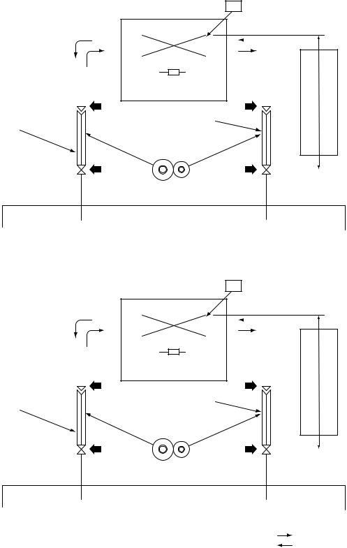
6. REFRIGERANT CYCLE DIAGRAM
RAS-M10YDV-E, RAS-M10YDCV-E
RAS-M13YDV-E, RAS-M13YDCV-E
TC
INDOOR UNIT
Evaporator
|
|
|
|
|
|
|
|
|
|
|
|
|
|
|
|
|
|
|
|
|
|
|
|
|
|
|
|
|
|
|
|
|
• |
|
|
|
|
|
|
|
|
|
|
|
|
|
|
|
|
|
|
|
|
|
|
|
|
|
|
|
|
|
|
|
|
|
|
|
Multi-blade fan |
||||||||||
|
|
TA |
|||||||||||||
|
|
|
|
|
|
|
|
|
|
|
|
|
|
|
|
Connecting pipe |
|
|
Connecting pipe |
||||||||||||
Thickness : 0.8mm |
|
|
Thickness : 0.8mm |
||||||||||||
Ø9.52 |
|
Ø6.35 |
|
|
|
|
|
|
|
|
|||||
Sectional shape of heat insulator
OUTDOOR UNIT
RAS-M16YDV-E, RAS-M16YDCV-E
TC
INDOOR UNIT
Evaporator
|
|
|
|
|
|
|
|
|
|
|
|
|
|
|
|
|
|
|
|
|
|
|
|
|
|
|
|
|
|
|
|
|
• |
|
|
|
|
|
|
|
|
|
|
|
|
|
|
|
|
|
|
|
|
|
|
|
|
|
|
|
|
|
|
|
|
|
|
|
Multi-blade fan |
||||||||||
|
|
TA |
|||||||||||||
|
|
|
|
|
|
|
|
|
|
|
|
|
|
|
|
Connecting pipe |
|
|
Connecting pipe |
||||||||||||
Thickness : 0.8mm |
|
|
Thickness : 0.8mm |
||||||||||||
Ø12.7 |
|
Ø6.35 |
|
|
|
|
|
|
|
|
|||||
Sectional shape of heat insulator
OUTDOOR UNIT
Allowable height difference |
Allowable pipe length |
|
|
|
|
Allowable height difference |
Allowable pipe length |
|
|
|
|
NOTE :  Gas leak check position
Refrigerant flow (Cooling)
Refrigerant flow (Heating*1) *1 : Heat pump model only
•The allowable pipe length, charge amount of refrigerant, and allowable height difference differ according to the outdoor unit to be combined.
For details, refer to the service manual of the outdoor unit to be combined.
–10 –
7. CONTROL BLOCK DIAGRAM
7-1. Indoor Unit
Indoor Unit P.C. Board (MMC-875)
|
|
|
|
|
|
|
|
M.C.U |
|
|
|
|
|
|
Heat Exchanger Sensor |
|
|
Functions |
|
|
|
Operation Display |
|||
|
|
|
|
|
||||||||
|
|
|
|
|
|
|
|
|
|
|
|
|
|
|
|
|
|
|
|
|
|
|
|
|
|
|
|
Temperature Sensor |
|
|
• Drain Pump Control |
|
|
|
|
|||
|
|
|
|
|
|
Timer Display |
||||||
|
|
|
|
|
|
|
|
|
|
|
|
|
|
|
|
|
|
|
|
|
|
|
|
|
|
Infrared Rays Signal Receiver |
|
|
|
• 3-minutes Delay at Restart for Compressor |
|
|
|
|
||||
|
|
|
|
|
|
|||||||
|
|
|
|
|
|
|
|
|
|
|
|
|
|
|
|
|
|
|
|
|
|
|
|
|
|
|
|
|
|
|
|
|
|
|
|
|
|
Check Display |
|
|
|
|
|
|
|
|
|
|
|
||
Infrared |
|
Initializing Circuit |
|
|
• Motor Revolution Control |
|
|
|
|
|||
|
|
|
|
|
||||||||
Rays |
|
|
|
|
|
|
|
|
|
|
|
|
|
Clock Frequency |
|
|
• Processing |
|
|
|
Indoor Fan Motor |
||||
|
|
|
|
|
|
|
|
|
||||
|
|
|
Oscillator Circuit |
|
|
(Temperature Processing) |
|
|
|
|
||
|
|
|
|
|
|
|
|
|
|
|
|
|
|
|
|
|
|
|
|
|
• Timer |
|
|
|
Voltage setup & |
|
|
|
|
|
|
|
|
|
|
|
TEMPORARY Switch |
|
|
|
|
|
|
|
|
|
|
|
|
|
|
|
|
|
|
|
|
|
|
• Serial Signal Communication |
|
|
|
|
|
|
|
|
|
|
|
|
|
|
|
|
|
|
|
|
|
|
|
|
|
|
|
|
|
|
Remote |
Power Supply |
Drain Pump ON/OFF Signal |
Float Switch |
Circuit |
|
|
|
Controller |
|
|
|
|
Noise Filter |
Drain Pump Relay |
Drain Pump |
|
|
Option |
|
|
|
|
|
|
|
Serial Signal Transmitter/Receiver |
|
From Outdoor Unit |
Serial Signal Communication |
|
|
Remote controller
|
RAS-M10YDV-E, M13YDV-E, M16YDV-E |
|
RAS-M10YDCV-E, M13YDCV-E, M16YDCV-E |
|||||||
|
|
(Heat Pump Model) |
|
|
(Cooling Only Mpdel) |
|||||
|
|
|
Infrared |
|
|
|
Infrared |
|||
|
|
|
Rays |
|
|
|
Rays |
|||
|
|
Wireless Remote Controller |
|
|
Wireless Remote Controller |
|||||
|
|
|
|
|
|
|
|
|
|
|
|
|
Operation (START/STOP) |
|
|
|
|
|
Operation (START/STOP) |
|
|
|
|
|
|
|
|
|
||||
|
|
|
|
|
|
|
|
|
|
|
|
|
|
|
|
|
|
|
|
|
|
|
|
Operation Mode Selection |
|
|
|
|
|
Operation Mode Selection |
|
|
|
|
AUTO, COOL, DRY, HEAT |
|
|
|
|
|
AUTO, COOL, DRY, FAM ONLY |
|
|
|
|
|
|
|
|
|
|
|
|
|
|
|
Thermo. Setting |
|
|
|
|
|
Thermo. Setting |
|
|
|
|
|
|
|
|
|
||||
|
|
|
|
|
|
|
|
|
|
|
|
|
|
|
|
|
|
|
|
|
|
|
|
Fan Speed Selection |
|
|
|
|
|
Fan Speed Selection |
|
|
|
|
|
|
|
|
|
||||
|
|
|
|
|
|
|
|
|
|
|
|
|
|
|
|
|
|
|
|
|
|
|
|
ON TIMER Setting |
|
|
|
|
|
ON TIMER Setting |
|
|
|
|
|
|
|
|
|
||||
|
|
|
|
|
|
|
|
|
|
|
|
|
|
|
|
|
|
|
|
|
|
|
|
OFF TIMER Setting |
|
|
|
|
|
OFF TIMER Setting |
|
|
|
|
|
|
|
|
|
||||
|
|
|
|
|
|
|
|
|
|
|
|
|
|
|
|
|
|
|
|
|
|
|
|
ECO (SLEEP) |
|
|
|
|
|
ECO (SLEEP) |
|
|
|
|
|
|
|
|
|
||||
|
|
|
|
|
|
|
|
|
|
|
|
|
|
|
|
|
|
|
|
|
|
|
|
Hi-POWER |
|
|
|
|
|
Hi-POWER |
|
|
|
|
|
|
|
|
|
||||
|
|
|
|
|
|
|
|
|
|
|
– 11 –

8. OPERATION DESCRIPTION
8-1. Outline of Air Conditioner Control
This air conditioner is a capacity-variable type air conditioner, which uses AC motors for the indoor fan motors and the outdoor fan motor. And the capacityproportional control compressor which can change the motor speed in the range around from 20 to 100 rps is mounted. The AC motor drive circuit is mounted to the indoor unit. The compressor and the inverter to control outdoor fan motor are mounted to the outdoor unit. The entire air conditioner is mainly controlled by the indoor unit controller.
The indoor unit controller drives the indoor fan motor based upon command sent from the remote controller, and transfers the operation command to the outdoor unit controller.
The outdoor unit controller receives operation command from the indoor unit side, and controls the outdoor fan and the pulse modulating valve. (PMV)
Besides, detecting revolution position of the compressor motor, the outdoor unit controller controls speed of the compressor motor by controlling output voltage of the inverter and switching timing of the supply power (current transfer timing) so that motors drive according to the operation command.
And then, the outdoor unit controller transfers reversely the operating status information of the outdoor unit to control the indoor unit controller.
As the compressor adopts four-pole brushless DC motor, the frequency of the supply power from inverter to compressor is two-times cycles of the actual number of revolution.
(1)Role of indoor unit controller
The indoor unit controller judges the operation commands from the remote controller and assumes the following functions.
•Judgment of suction air temperature of the indoor heat exchanger by using the indoor temp. sensor.
•Temperature setting of the indoor heat exchanger by using heat exchanger sensor (Prevent-freezing control)
•Indoor fan motor operation control
•LED display control
•Transferring of operation command signal (Serial signal) to the outdoor unit
•Reception of information of operation status (Serial signal including outside temp. data) from the outdoor unit and judgment/display of fail.
(2)Role of outdoor unit controller
Receiving the operation command signal (Serial signal) from the indoor controller, the outdoor unit performs its role.
• |
Compressor operation |
|
Operations fol- |
|
control |
||
• |
Operation control of |
|
lowed to judgment |
of serial signal |
|||
|
outdoor fan motor |
|
from indoor side. |
• |
PMV control |
• Detection of inverter input current and current release operation
• Over-current detection and prevention operation to transistor module (Compressor stop function)
• Compressor and outdoor fan stop function when serial signal is off (when the serial signal does not reach the board assembly of outdoor control by trouble of the signal system)
• Transferring of operation information (Serial signal) from outdoor unit to indoor unit
• Detection of outdoor temperature and operation revolution control
• Defrost control in heating operation ((Heat pump model only) Temp. measurement by outdoor heat exchanger and control for 4-way valve and outdoor fan)
(3) Contents of operation command signal (Serial signal) from indoor unit controller to outdoor unit controller
The following three types of signals are sent from the indoor unit controller.
• Operation mode set on the remote controller
• Compressor revolution command signal defined by indoor temperature and set temperature
(Correction along with variation of room temperature and correction of indoor heat exchanger temperature are added.)
• For these two types of signals ( [Operation mode] and [Compressor revolution] ), the outdoor unit controller monitors the input current to the inverter, and performs the followed operation within the range that current does not exceed the allowable value.
• Temperature of indoor heat exchanger by indoor heat exchanger sensor
(Minimum revolution control)
– 12 –
(4)Contents of operation command signal (Serial signal) from outdoor unit controller to indoor unit controller
The following signals are sent from the outdoor unit controller.
•The current operation mode
•The current compressor revolution
•Outdoor temperature
•Existence of protective circuit operation
For transferring of these signals, the indoor unit controller monitors the contents of signals, and judges existence of trouble occurrence.
Contents of judgment are described below.
•Whether distinction of the current operation status coincide with the operation command signal
•Whether protective circuit operates
When no signal is received from the outdoor unit controller, it is assumed as a trouble.
8-1-1. Capacity Control
The cooling capacity is varied by changing compressor motor speed. The inverter changes compressor motor speed by changing AC 220 – 240V power to DC once, and controls capacity by changing supply power status to the compressor with transistor module (includes 6 transistors). The outline of the control is as follows : The revolution position and revolution speed of the motor are detected by detecting winding electromotive force of the compressor motor under operation, and the revolution speed is changed so that the motor drives based upon revolution speed of the operation command by changing timing (current transfer timing) to exchange inverter output voltage and supply power winding.
Detection of the revolution position for controlling is performed 12 times per 1 revolution of compressor.
The range of supply power frequency to the compressor differs according to the operation status.
8-1-2. Current Release Control
The outdoor main circuit control section (Inverter assembly) detects the input current to the outdoor unit. If the current value with compressor motor speed instructed from indoor side exceeds the specified value, the outdoor main circuit control section controls compressor motor speed by reducing motor speed so that value becomes closest to the command within the limited value.
8-1-3. Indoor Fan Control (AC Fan Motor)
The indoor fan is operated by motor speed non-step variable AC phase control drive system. For airflow rate, motor speed is controlled manually in five steps (LOW, LOW+, MED, MED+, HIGH), or automatically in AUTO mode adjusted according to the room temperature. It is not selected by relay, so selecting sound does not generate.
Table 8-1-1 shows the motor speed.
This function performs the phase output constant control of the fan motor.
(Does not control the revolution speed.)
Since the motor speed varies according to the external static pressure, the values described in the table are criteria to confirm the motors, etc. However, the maximum revolution speed is limited to 1300rpm for protection of the terminal voltage of the running capacitor.
Table 8-1-1 Reference fan speed
Operation mode |
Fan mode |
|
Motor speed (rpm) |
|
|
|
|
|
|
|
|||
M10 |
M13 |
M16 |
|
|||
|
|
|
||||
|
|
|
|
|
||
COOL |
H |
900 to 1150 |
950 to 1200 |
1000 to 1250 |
||
|
|
|
|
|
||
L |
600 to 800 |
650 to 850 |
700 to |
900 |
||
|
||||||
|
|
|
|
|
||
HEAT |
H |
900 to 1150 |
950 to 1200 |
1000 to 1250 |
||
|
|
|
|
|
||
L |
650 to 850 |
700 to 900 |
750 to |
950 |
||
|
||||||
|
|
|
|
|
|
|
– 13 –
8-2. Description of Operation Circuit
•Turning [ON] the breaker flashes the operation lamp.
This is the display of power-ON (or notification of power failure).
•When pushing [START/STOP] button of the remote controller, receive sound is issued from the main unit.
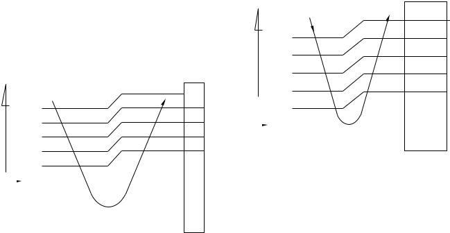
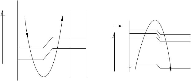
8-2-1. Fan Only Operation
(The Remote controller MODE Button is Set to the FAN ONLY Operation)
•Once the setting is made, the operation mode is memorized in the microcomputer so that the same operation can be effected thereafter simply by pushing [START/STOP] button.
•When the FAN button is set to the AUTO position, the indoor fan motor operates as shown in Fig. 8-2-1. When the FAN SPEED button is set manually, the motor operates with a constant air flow.
•ECO mode cannot be set.
|
|
˚C |
|
|
|
|
|
|
|
||
|
|
temp.) |
+3 |
M+ |
|
|
|
|
|
||
|
|
(Set– |
+2 |
||
|
|
|
|||
|
|
|
|
+2.5 |
*1 |
|
|
|
|
|
|
|
|
temp.) |
+1.5 |
*1 |
|
|
|
*1 |
|||
|
|
|
|
||
|
|
|
|
+1 |
|
|
|
(Room |
L– |
||
|
|
+0.5 |
|||
|
|
|
|
||
|
|
|
|
|
|
Set |
|
|
|
0 |
|
|
|
|
|||
temp. |
|
|
|
|
|
|
|
|
|
|
(Set temp.) 25˚C |
|
|
|
|
|
|
NOTE :
*1: Calculated from difference in motor speed of M+ and L–, and controlled.
Fig. 8-2-1 Auto setting of air flow
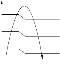
8-2-2. Cooling Operation
(The Remote controller MODE Button is Set to the COOL Position)
•Once the setting is made, the operation mode is memorized in the microcomputer so that the same operation can be effected thereafter simply by pushing [START/STOP] button.
•A cooling operation signal is transmitted to outdoor unit.
•The indoor fan motor operates as shown in Fig.8-2- 2 when FAN button is set to AUTO.
•The motor operates with a constant air flow when the FAN button is set manually.
•The outdoor unit controls the outdoor fan and the compressor motor speed according to the operation command signal sent from the indoor unit.
temp.) |
˚C |
|
|
||
|
|
||||
+3 |
|
|
|||
|
|
|
|
||
(Set– |
+2.5 |
|
M+ |
||
*1 |
|||||
|
|
|
|
||
temp.) |
+2 |
|
|
||
+1.5 |
*1 |
||||
|
|
|
|
||
(Room |
+1 |
*1 |
|||
|
L– |
||||
|
|
|
|
||
|
|
+0.5 |
|
|
|
Set |
|
0 |
|
|
|
|
|
In normal |
|||
temp. |
|
|
|
||
|
|
|
–0,5 |
|
operation |
|
|
|
|
|
|
|
|
|
|
|
|
NOTE :
*1: Calculated from difference in motor speed of M+ and L–, and controlled.
Fig. 8-2-2 Setting of air flow [Air Flow AUTO]
(1)Cooling capacity control
•The cooling capacity and room temperature are controlled by changing the compressor motor speed according to both the difference between the temperature detected by the room temperature sensor and the temperature set by TEMP button and also any change in room temperature.
•When compressor has been activated or reactivated, compressor motor speed goes up with restricting the maximum speed gradually from operation start.
•When room temperature is lower than set temperature, indoor fan motor is operated at fan speed L– as shown in Fig. 8-2-2 while the
outdoor unit stops.
– 14 –
(2)Prevent-freezing control
If temperature of indoor heat exchanger detected by the indoor heat exchanger sensor is 4°C or lower, compressor motor speed is gradually lowered to prevent freezing of the indoor heat exchanger. If temperature is 6°C or higher, return the operation to the above item (1).
(3)Limit for maximum compressor motor speed by indoor fan speed
When outdoor temperature sensor detected 32°C or lower, and indoor heat exchanger sensor detected 15°C or lower, the maximum compressor motor speed is limited by the indoor fan speed.
8-2-3. DRY Operation
(The Remote controller MODE Button is Set to the DRY Position)
•Once the setting is made, the operation mode is memorized in the microcomputer so that the same operation can be effected thereafter simply by pushing [START/STOP] button.
•Dry operation signal is transmitted to outdoor unit.
•The Cooling operation giving priority to dehumidifying, which restrains the indoor fan speed and compressor motor speed, is performed.
•The indoor fan motor operates as shown in Fig. 8- 2-3. (Fan speed is AUTO only.)
•The outdoor unit controls the outdoor fan relay and the compressor motor speed according to the operation command signal sent from the indoor unit.
temp.)(Set |
+2.5 |
|
|
+2.0 |
L– |
||
|
|||
– |
+1.5 |
|
|
|
*1 |
||
temp.) |
|
||
+1.0 |
|
||
|
|
||
(Room |
|
UL |
|
+0.5 |
|
||
|
|
Set  0 temp.
–0.5
NOTE :
*1 : Middle motor speed between L– and UL
Fig. 8-2-3 Setting of air flow
(1)Dehumidifying-preferential Cooling capacity control
•The cooling capacity and room temperature are controlled by changing the compressor motor speed according to both the difference between the temperature detected by the room temperature sensor and the temperature set by TEMP button and also any change in room temperature.
•When the air conditioner operates in Dry mode, the maximum compressor motor speed is restricted.
While multiple indoor units operate, compressor motor speed is calculated in the outdoor unit to operate.
•When room temperature is lower than set temperature, indoor fan motor is operated at fan speed UL as shown in Fig. 8-2-3 while the outdoor unit stops.
•Other controls than the above-mentioned controls are common to those of Cooling operation.
8-2-4. Heating Operation
(Heat pump model only)
Transferring of heating operation signal from indoor unit to outdoor unit starts.
The indoor fan motor operates by the room temperature when selecting “AUTO” of “FAN” as shown in Fig. 8-2-4, and operates with a set air flow when selecting “Low” to “High”.
However, to prevent cold draft, revolution speed of the fan is restricted by indoor heat exchanger temperature when air flow is AUTO (Fig. 8-2-5) and starting of FAN Manual.
[Basic control]
Set |
0 |
|
LOW |
|
|||
temp. |
–0.5 |
|
|
|
–1 |
* 1 |
|
– |
–1.5 |
||
(Roomtemp.) temp.)(Set |
–2 |
|
* 2 |
|
|||
|
|
M+ |
|
|
|
|
|
–5.0
–5.5
HIGH
[FAN AUTO]
NOTE :
*1, *2 : Approximate revolution speed of M+ and L to linear according to temperature.
Fig. 8-2-4 Setting of air flow
– 15 –
[Cold draft preventing control]
The upper limit of fan revolution speed is shown below.
|
TC |
|
|
|
(˚C) |
|
|
|
|
|
HIGH |
44 |
33 |
|
|
|
|
||
43 |
32 |
|
Approximate |
|
|||
|
|
|
|
|
|
|
revolution speed |
31 |
20 |
|
of HIGH and SUL |
|
linear by Tc. |
||
30 |
19 |
|
SUL*3 |
|
|||
|
|
|
|
A + 4 |
A*2 |
|
SUL ( NOTE : *1) |
A – 8 |
A – 8 |
|
|
|
|||
|
|
|
Stop |
FAN |
Starting |
|
|
of FAN |
|
|
|
AUTO |
|
|
|
Manual |
|
|
|
|
|
|
|
|
|
|
|
NOTES :
*1 Stops for 2 minutes after thermostat-OFF.
*2 24°C when the set temp. is 24°C or more Set temp. when the set temp. is below 24°C
*3 SUL : Super ultra low
Fig. 8-2-5 Cold draft preventing control
The outdoor unit controls the outdoor fan based upon the operation signal sent from the indoor unit, and also controls revolution speed of the compressor motor.
The power coupler for 4-way valve is turned on, and turned off in defrost operation.
(1)Heating capacity control
Calculate the difference between temperature detected by room temp. sensor every minute and the set temp. set on “Temp. indicator” and variation amount of room temp.
Then, obtain the correction amount of the command signal, and correct the current frequency command signal.
(2)High-temp. release control
If temperature of the indoor heat exchanger detected by the indoor heat exchanger sensor is 58°C or higher, compressor motor speed is gradually lowered to prevent over-temp. rising of compressed pressure.
If temperature becomes below 51°C, return to above item (1).
(3)Defrost control
1)Detection of frost
In heating operation, time duration while the compressor operates is counted, and defrost operation starts by any condition described below.
a.The counted time is 28 minutes or more, and status that temperature of the outdoor heat exchanger detected by the outdoor heat exchanger is –20°C or lower continued for 3 minutes or more.
b.The counted time is 28 minutes or more, and status that temperature of the outdoor heat exchanger detected by the outdoor heat exchanger is –8°C or lower and temperature lowered by 2.5 °C than the minimum value of the outdoor heat exchanger during 10 to 15 minutes count time continued for 3 minutes or more.
c.The counted time is 34 minutes or more, and status that temperature of the outdoor heat exchanger detected by the outdoor heat exchanger is –5°C or lower and temperature lowered by 3.0 °C than the minimum value of the outdoor heat exchanger during 10 to 15 minutes count time continued for 3 minutes or more.
d.The counted time is 4 hours or more, and status that temperature of the outdoor heat exchanger detected by the outdoor heat exchanger is 0°C or lower and temperature lowered by 1.0 °C than the minimum value of the outdoor heat exchanger during 10 to 15 minutes count time continued for 3 minutes or more.
e.If the following three conditions are satisfied, defrost operation (Timer defrost) starts after heating operation for 48 minutes.
•Setting on remote controller, HEAT (mode), HIGH (Fan), 30°C (temp.).
‚Room temp. is 19°C to 24°C, and outside air temp. is 5°C or lower.
ƒDefrost operation has been already performed once.
2)Defrost operation
Operation of the compressor is stopped once, turn off power coupler for 4-way valve after 10 seconds, and then exchange the
4-way valve.
After 20 seconds, restart operation of the compressor. Turn off the outdoor fan just when the compressor stopped.
If temperature of the indoor heat exchanger is lower than settimg temperature, stop the indoor fan.
– 16 –

3)Defrost reset
Resetting operation from defrost to heating is performed when any one of the following conditions is satisfied.
a.Temperature of the outdoor heat exchanger rose to +8°C or higher.
b.A status that temperature of the outdoor heat exchanger is +5°C or higher continued for 80 seconds.
c.Defrost operation continued for 10 minutes.
In resetting defrost operation, the compressor stops for 50 seconds if defrost has started under condition a. to d. in item 1, but the compressor is reset to heating operation keeping operated if defrost has started under condition e. in item 1.
8-2-5. Auto Operation
(1)As shown in Fig. 8-2-6, the operation mode (COOL, FAN ONLY, HEAT) is selected according to the outside temperature when the operation has started.
The operation in Fan mode continues until an operation mode is selected.
If the room temperature is 20°C or higher when “AUTO” operation started within 2 hours after “HEAT” operation had stopped, select an operation mode after Fan operation of ultra low fan.
In AUTO operation, the set temperature of each operation can be corrected by the remote controller in the range of 17 to 30°C.
Outdoor temp. (˚C)
Cool mode
22
Fan only mode
20
Fan only mode (Cooling only model) Heat mode (Heat pump model)
Fig. 8-2-6
(2)After selecting the operation mode (COOL, FAN ONLY, HEAT), select an operation mode again when a status that the compressor was turned off by the room temperature or outside air temperature continues for 15 minutes.
8-2-6. ECO Timer Operation
When you push the ECO button during cooling, Dry, heating, or A operation, the air conditioner will start the following operation.
The fan speed will be automatically controlled.
•Cooling operation  / Dry operation
In the operation suppression zone, where capacity is kept to the minimum, overcooling is prevented by raising the temperature setting by 1°C after 1 hour and by 2°C after 2 hours of operation.
The room temperature is thus regulated between the operation suppression zone and the set tem-
perature.
start |
|
|
|
Operation |
1˚C |
2˚C |
|
|
|||
1 hour |
Set |
||
temperature |
|||
|
2 hours
Fig. 8-2-7
•Heating operation  (Heat pump model only)
In the operation suppression zone, where capacity is kept to the minimum, overheating is prevented by lowering the temperature setting by 1°C after 1 hour and by 2°C after 2 hours of operation.
The room temperature is thus regulated between the set temperature and the operation suppression
zone.
|
|
Set temperature |
start |
1˚C |
2˚C |
Operation |
1 hour |
suppression zone |
|
|
|
|
2 hours |
Operation |
Fig. 8-2-8
8-2-7. High POWER Operation
When you push the Hi-POWER button during cooling, heating, or A operation, the air conditioner will start the following operation. (A operation : Auto change over)
•Cooling operation
Performs the cooling operation lower than the setting temperature.
When the room temperature is above the setting temperature. In addition, fan speed is high*.
Once room temperature is within 1°C of the setting temperature.
*Noise level raises in accordance with fan speed.
•Heating operation (Heat pump model only)
Performs the heating operation at 2°C higher than
the setting temperature.
– 17 –
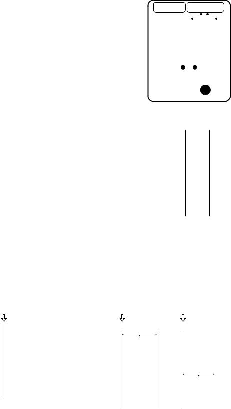
8-3. TEMPORARY Operation
•Setting the TEMPORARY switch to “AUTO” starts the automatic operation, to “COOL” starts the cooling operation (LOW), respectively.
•Setting the TEMPORARY switch to “AUTO” or “COOL”, the operation can’t be performed from the remote controller. (without “STOP”)
•Temporary Auto Operation is operated with the set temperature fixed at 24°C.
•Temporary Cooling Operation is operated with Indoor fan speed fixed to Low and with compressor motor speed fixed to 28.0Hz.
To stop the temporary operation,
set the switch to “AUTO RESTART OFF”.
TEMPORARY |
|
AUTO RESTART |
|||||||||||||||||
COOL AUTO |
|
|
|
|
|
|
|
OFF ON |
|||||||||||
|
|
|
|
|
|
|
|
|
|
|
|
|
|
|
|
|
|
|
|
|
|
|
|
|
|
|
|
|
|
|
|
|
|
|
|
|
|
|
|
|
|
|
|
|
|
|
|
|
|
|
|
|
|
|
|
|
|
|
|
|
|
|
|
|
|
|
|
|
|
|
|
|
|
|
|
|
|
|
|
|
|
|
|
|
|
|
|
|
|
|
|
|
|
|
|
|
|
||
VOLTAGE1 |
|
|
|
|
|
|
|
|
|
|
|
||||||||
220V/230V |
|
|
|
|
|
240V |
|||||||||||||
|
|
|
|
|
|
|
|
|
|
|
|
|
|
|
|
||||
VOLTAGE2 |
|
|
|
|
|
|
REMOCON |
||||||||||||
|
|
|
|
|
|
|
|
|
|
|
|
|
|
|
|
|
|
|
|
220V |
|
|
|
|
230V |
A |
|
|
|
B |
|||||||||
|
|
|
|
|
|
|
|
|
|
|
|
|
|
|
|
|
|
|
|
|
|
|
|
|
|
|
|
|
|
|
|
|
|
|
|
|
|
|
|
|
|
|
|
|
|
|
|
|
|
|
|
|
|
|
|
|
|
|
|
Fig. 8-3-1
8-4. Control of Drain-up Kit (Option)
8-4-1. Dain Control
•In cooling, and dry operation, drain pump is actuated to drain up.
[OPERATION CONTROL]
During cooling, and drying operation :
Drain pump ON.
|
ON |
|
Thermo OFF |
Thermo ON |
|||
Drain pump |
|
ON |
|
|
|
|
|
|
|
|
|
|
|
|
|
|
|
|
|
|
|
||
Float switch |
|
CLOSE |
|
|
|
|
|
|
|
|
|
|
|
|
|
|
|
|
|
|
|
||
Compressor |
|
ON |
|
OFF |
|
ON |
|
|
|
|
|
|
|
|
|
|
|
|
|
|
|
||
Indoor fan |
|
ON |
|
|
|
|
|
|
|
|
|
|
|
|
|
Fig. 8-4-1
8-4-2. Over Flow Check Control
•Drain level is checked by float switch. If the float switch is actuated (OPEN), micro-computer cut the signal to the outdoor unit and power supply to stop the outdoor unit, operate the drain pump exert to drain out.
•In fan only, heating operation (Heat pump model only), and even in stoppage but while float switch is actuated, drain pump is ON (Operation).
[OVERFLOW CHECK AND CONTROL]
|
Operation starts at overflowing |
Overflow detection durling operation |
|||||||||
Operation starts |
Overflow detection |
Overflow stops |
|||||||||
Drain pump |
|
|
|
|
|
|
|
|
|
|
|
|
|
ON |
ON |
|
|
ON |
|||||
|
|
|
|
|
|
|
|
|
|
|
|
|
|
|
|
|
*1 |
2'30" |
|
|
|
||
Float switch |
|
|
|
|
|
|
|
|
|
|
|
|
|
OPEN |
CLOSE |
|
OPEN |
|
CLOSE |
||||
Compressor |
|
|
|
|
|
|
|
|
|
|
|
|
|
|
|
|
|
|
|
|
|
|
|
|
|
OFF |
|
ON |
|
|
OFF |
|
*2 2'30" |
ON |
|
|
|
|
|
|
|||||||
Indoor fan |
|
|
|
|
|
|
|
|
|
|
|
|
|
ON |
ON |
|
|
|
|
||||
|
|
|
|
|
|
|
|
|
|
|
|
|
Compressor stops. |
|
|
|
|
|
|
|
|||
|
Drain pump continues operation. |
|
|
|
|
|
|
|
|||
*1 If the float switch is not reset (closed) within 2 minutes 30 seconds, the operation lamp flashes. (5Hz)
*2 When the float switch has been reset, the system recognizes the flashing operation lamp and the operation of the outdoor unit resumes after 2 minutes 30 seconds.
Fig. 8-4-2
– 18 –
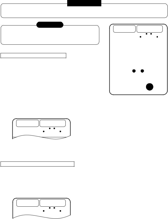
8-5. Auto Restart Function
This unit is equipped with an Automatic restarting function which allows the unit to restart and resume the set operating conditions in the event of a supply power shutdown without the use of the remote controller.
The operation will resume without warning three minutes after the power is restored.
INFORMATION
The AUTO RESTART FUNCTION is not set to work on shipment from the factory, and so it is necessary to set it to function as required.
CAUTION
When wired remote controller is connected and in case of its batteries are exhausted or not used, the unit restart FAN ONLY operation.
HOW TO SET THE AUTO RESTART
To set the auto restart function, proceed as follows:
TEMPORARY |
|
|
AUTO RESTART |
||||||||||||||||||||||||
COOL AUTO |
|
|
|
|
|
|
|
|
|
OFF ON |
|||||||||||||||||
|
|
|
|
|
|
|
|
|
|
|
|
|
|
|
|
|
|
|
|
|
|
|
|
|
|
|
|
|
|
|
|
|
|
|
|
|
|
|
|
|
|
|
|
|
|
|
|
|
|
|
|
|
|
|
|
|
|
|
|
|
|
|
|
|
|
|
|
|
|
|
|
|
|
|
|
|
|
|
|
|
|
|
|
|
|
|
|
|
|
|
|
|
|
|
|
|
|
|
|
|
|
|
|
|
|
|
|
|
|
|
|
|
|
|
|
|
|
|
|
|
|
|
|
|
|
|
|
|
|
|
|
|
|
|
|
|
|||
VOLTAGE1 |
|
|
|
|
|
|
|
|
|
|
|
|
|
|
|
|
|
|
|
||||||||
220V/230V |
|
|
|
|
|
|
|
240V |
|||||||||||||||||||
|
|
|
|
|
|
|
|||||||||||||||||||||
|
|
|
|
|
|
|
|
|
|
|
|
|
|
|
|
|
|
|
|||||||||
VOLTAGE2 |
|
|
|
|
|
|
|
|
REMOCON |
||||||||||||||||||
|
|
|
|
|
|
|
|
|
|
|
|
|
|
|
|
|
|
|
|
|
|
|
|
|
|
|
|
220V |
|
|
|
|
|
|
230V |
A |
|
|
|
|
|
|
|
|
|
B |
|||||||||
|
|
|
|
|
|
|
|
|
|
|
|
|
|
|
|
|
|
|
|
|
|
|
|
|
|
|
|
|
|
|
|
|
|
|
|
|
|
|
|
|
|
|
|
|
|
|
|
|
|
|
|
|
|
|
|
|
|
|
|
|
|
|
|
|
|
|
|
|
|
|
|
|
|
|
|
|
|
|
|
|
|
|
|
|
|
|
|
|
|
|
|
|
|
|
|
|
|
|
|
|
|
|
|
|
|
|
|
|
|
|
|
|
OPERATION |
MOTION |
|||||||||||
|
|
||||||||||||
Slide the slide switch to AUTO RESTART ON side. |
When you set to “ON” position of Auto restart, Pi Pi Pi |
||||||||||||
|
|
|
|
|
|
|
|
|
|
|
|
|
sound (3 times) are appear. |
TEMPORARY |
AUTO RESTART |
(During power supply to the unit) |
|||||||||||
COOL AUTO |
|
|
|
OFF ON |
When power supplying return, system will be restart |
||||||||
|
|
|
|
|
|
|
|
|
|
|
|
|
|
|
|
|
|
|
|
|
|
|
|
|
|
|
automatically. |
|
|
|
|
|
|
|
|
|
|
|
|
|
|
|
|
|
|
|
|
|
|
|
|
|
|
|
|
|
|
|
|
|
|
|
|
|
|
|
|
|
|
•The Auto Restart function will not accept an instruction if timer operation with the remote controller is selected. (Please refer to the section of setting the timer operation.)
HOW TO CANCEL THE AUTO RESTART
To cancel the AUTO RESTART function, proceed as follows:
The system will now be required to manually restart with the remote controller after the main supply is returned.
|
|
|
OPERATION |
MOTION |
||||||||||||
|
|
|||||||||||||||
Slide the slide switch to AUTO RESTART OFF side. |
When you set to “OFF” position of Auto restart, Pi Pi Pi |
|||||||||||||||
|
|
|
|
|
|
|
|
|
|
|
|
|
|
|
|
sound (3 times) are appear. |
|
|
TEMPORARY |
AUTO RESTART |
(During power supply to the unit) |
||||||||||||
|
|
COOL AUTO |
|
|
|
OFF ON |
When power supplying return, system will not be |
|||||||||
|
|
|
|
|
|
|
|
|
|
|
|
|
|
|
|
|
|
|
|
|
|
|
|
|
|
|
|
|
|
|
|
|
|
|
|
|
|
|
|
|
|
|
|
|
|
|
|
|
|
restart automatically. |
|
|
|
|
|
|
|
|
|
|
|
|
|
|
|
|
|
|
|
|
|
|
|
|
|
|
|
|
|
|
|
|
|
|
|
|
|
|
|
|
|
|
|
|
|
|
|
|
|
|
|
– 19 –
Loading...